EP0209697A1 - Ventileinstellplatte - Google Patents
Ventileinstellplatte Download PDFInfo
- Publication number
- EP0209697A1 EP0209697A1 EP86107809A EP86107809A EP0209697A1 EP 0209697 A1 EP0209697 A1 EP 0209697A1 EP 86107809 A EP86107809 A EP 86107809A EP 86107809 A EP86107809 A EP 86107809A EP 0209697 A1 EP0209697 A1 EP 0209697A1
- Authority
- EP
- European Patent Office
- Prior art keywords
- valve
- plate
- cam
- adjusting plate
- adjusting pad
- Prior art date
- Legal status (The legal status is an assumption and is not a legal conclusion. Google has not performed a legal analysis and makes no representation as to the accuracy of the status listed.)
- Withdrawn
Links
- 229910010293 ceramic material Inorganic materials 0.000 claims abstract description 7
- 238000002485 combustion reaction Methods 0.000 claims abstract description 7
- 239000000919 ceramic Substances 0.000 description 3
- 239000002184 metal Substances 0.000 description 3
- 230000001133 acceleration Effects 0.000 description 2
- 239000000463 material Substances 0.000 description 2
- 229910000831 Steel Inorganic materials 0.000 description 1
- 239000011324 bead Substances 0.000 description 1
- 239000011248 coating agent Substances 0.000 description 1
- 238000000576 coating method Methods 0.000 description 1
- 230000001419 dependent effect Effects 0.000 description 1
- 230000007774 longterm Effects 0.000 description 1
- 238000000034 method Methods 0.000 description 1
- 239000000203 mixture Substances 0.000 description 1
- 230000035939 shock Effects 0.000 description 1
- 239000010959 steel Substances 0.000 description 1
Images
Classifications
-
- F—MECHANICAL ENGINEERING; LIGHTING; HEATING; WEAPONS; BLASTING
- F01—MACHINES OR ENGINES IN GENERAL; ENGINE PLANTS IN GENERAL; STEAM ENGINES
- F01L—CYCLICALLY OPERATING VALVES FOR MACHINES OR ENGINES
- F01L1/00—Valve-gear or valve arrangements, e.g. lift-valve gear
- F01L1/20—Adjusting or compensating clearance
- F01L1/205—Adjusting or compensating clearance by means of shims or the like
-
- F—MECHANICAL ENGINEERING; LIGHTING; HEATING; WEAPONS; BLASTING
- F01—MACHINES OR ENGINES IN GENERAL; ENGINE PLANTS IN GENERAL; STEAM ENGINES
- F01L—CYCLICALLY OPERATING VALVES FOR MACHINES OR ENGINES
- F01L1/00—Valve-gear or valve arrangements, e.g. lift-valve gear
- F01L1/12—Transmitting gear between valve drive and valve
- F01L1/14—Tappets; Push rods
- F01L1/143—Tappets; Push rods for use with overhead camshafts
-
- F—MECHANICAL ENGINEERING; LIGHTING; HEATING; WEAPONS; BLASTING
- F02—COMBUSTION ENGINES; HOT-GAS OR COMBUSTION-PRODUCT ENGINE PLANTS
- F02F—CYLINDERS, PISTONS OR CASINGS, FOR COMBUSTION ENGINES; ARRANGEMENTS OF SEALINGS IN COMBUSTION ENGINES
- F02F7/00—Casings, e.g. crankcases
- F02F7/0085—Materials for constructing engines or their parts
- F02F7/0087—Ceramic materials
-
- F—MECHANICAL ENGINEERING; LIGHTING; HEATING; WEAPONS; BLASTING
- F02—COMBUSTION ENGINES; HOT-GAS OR COMBUSTION-PRODUCT ENGINE PLANTS
- F02B—INTERNAL-COMBUSTION PISTON ENGINES; COMBUSTION ENGINES IN GENERAL
- F02B2275/00—Other engines, components or details, not provided for in other groups of this subclass
- F02B2275/20—SOHC [Single overhead camshaft]
Definitions
- the invention relates to a valve timing plate for internal combustion engines, which is arranged above the valve lifter and is acted upon by the control cam.
- valves which release or shut off the inlet and outlet lines in relation to the cylinder space in accordance with the working cycle of the engine.
- the valve disk is pressed against the valve seat on the cylinder head under spring force, and they are driven by cams arranged on the camshaft, in order to achieve good filling and rapid emptying of the cylinder, the fastest possible opening and closing of the valves is essential.
- the valve is suddenly accelerated to a high speed by the action of the control cam on the valve tappet, resulting in a strong impact. With this acceleration up to the maximum value of the speed, there is direct contact between the cam and the acted valve element.
- the course of movement is largely determined by the shape of the cam.
- the wear of the adjusting plate is also dependent on the shape of the cam, so that for the reasons given certain compromises have to be made which are at the expense of the valve clearance and thus the engine performance. This results in a need for a remedy beyond the complex application of hard metal on valve setting plates, on the one hand in order to achieve the optimal operating conditions of the valve control, and on the other hand to keep wear as low as possible.
- the invention addresses these problems and, in order to solve this problem, proposes to design the valve timing plate from a fired ceramic material with a polished surface when controlling the valve of an internal combustion engine.
- This ceramic plate replaces the previously used metal valve adjusting plate guided by a guide sleeve bearing against the valve tappet by a ceramic plate of high surface quality.
- the surface can be lapped, ground or polished.
- Such a material is known to be distinguished by high compressive strength as well as long-term impact stress.
- the wear of such a valve adjusting plate made of a ceramic material is significantly less than that of the usual metal plates.
- the cams can be provided with an optimal shape, so that the control times can also be optimized and thereby the opening and closing process can be influenced in a sense that the Engine performance noticeably influenced.
- Ceramic mixtures of various types are suitable for the inventive design of a valve timing plate made of ceramic material, the permanent impact strength being from is of crucial importance.
- the surface coating of such valve timing plates can be adapted to the respective requirements in a comparatively wide range.
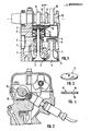
- the drawing shows the arrangement of a hanging valve controlled above.
- This consists of the valve tappet 1 with the valve plate 3 interacting with the valve seat 2.
- the tappet 1 is guided in a bush 4 which has a plate 5 on which the valve spring 6 is supported, the other end of which rests on the plate 7.
- the cam-side end of the valve tappet 1 is encompassed by a guide sleeve 8, the outer edge 9 of which extends beyond the surface 10 and serves to guide the valve adjusting plate 11, which rests freely rotatably on the surface 10 within the projecting edge 9.
- a number of cams 13 corresponding to the number of valves to be controlled are arranged, which act once on the valve setting plate 11 with each revolution of the shaft 12 and, via this and the guide sleeve 8, accelerate the valve tappet 1 and the valve disk 3 to the maximum and at retard the opposite movement accordingly, so that the valve plate 3 lifts off the valve seat 2 in a very short time and then comes back to the system.
- the valve adjusting plate 11 consists of a fired ceramic material, the surface 15 of which is ground, polished and / or lapped, so that the lowest possible amount of friction results between the cam 13 and the surface 15.
Landscapes
- Engineering & Computer Science (AREA)
- Mechanical Engineering (AREA)
- General Engineering & Computer Science (AREA)
- Chemical & Material Sciences (AREA)
- Ceramic Engineering (AREA)
- Combustion & Propulsion (AREA)
- Valve-Gear Or Valve Arrangements (AREA)
Abstract
Die Erfindung bezieht sich auf eine Ventileinstellplatte für Verbrennungsmotore, die über dem Ventilstößel angeordnet ist und von dem Steuernocken beaufschlagt wird, wobei die Einstellplatte aus einem gebrannten keramischen Werkstoff mit polierter Oberfläche besteht.
Description
- Die Erfindung richtet sich auf eine Ventileinstellplatte für Verbrennungsmotore, die über dem Ventilstößel angeordnet ist und von dem Steuernocken beaufschlagt wird.
- Bei Verbrennungsmotoren ist eine mehr oder weniger große Anzahl von Ventilen vorhanden, die dem Arbeitsspiel des Motors entsprechend die Einlaß- und Auslaßleitungen gegenüber dem Zylinderraum freigeben oder absperren. Der Ventilteller wird unter Federkraft gegen den Ventilsitz am Zylinderkopf gepreßt, und sie werden durch auf der Nockenwelle angeordnete Nocken angetrieben, wobei es zur Erzielung einer guten Füllung und eines raschen Entleerens des Zylinders auf ein schnellstmögliches öffnen und Schließen der Ventile entscheidend ankommt. Hierzu wird das Ventil durch Einwirkung des Steuernockens auf den Ventilstößel plötzlich auf eine hohe Geschwindigkeit beschleunigt, wodurch ein starker Stoß entsteht. Bei dieser Beschleunigung bis zum Höchstwert der Geschwindigkeit besteht ein unmittelbarer Berührungskontakt zwischen Nocken und beaufschlagtem Ventilelement. Der Bewegungsablauf wird maßgeblich durch die Nockenform bestimmt. Hierbei tritt ein plötzlicher Beschleunigungswechsel zu Anfang und gegen Ende der Ventilbewegung auf. Daraus resultieren hohe Stoßbeanspruchungen, zu denen die thermische Beanspruchung noch hinzukommt. Der Verschleiß des von dem Nocken beaufschlagten Elements, vielfach eine Ventileinstellplatte, ist dementsprechend außerordentlich hoch. Deshalb werden hierfür Sonderstähle verwendet, auf die in Sonderfällen noch Hartmetall aufgeschweißt wird. All dies kann nicht verhindern, daß die dem Nocken unmittelbar ausgesetzte Ventileinstellplatte einer hohen Beanspruchung unterliegt. Da sie infolge ihrer Kreisform noch eine Kreisbewegung um ihre Achse ausführt, wird durch die Nockenbeanspruchung zunehmend Material im Zentrum abgetragen, und es bildet sich nach und nach ein ringförmiger Wulst aus. Dieser Verschleiß an den Ventileinstellplatten verändert naturgemäß das Ventilspiel eines Verbrennungsmotors, weshalb diese Teile in kurzen Zeitabständen gewartet und ggf. ersetzt werden müssen, um die Leistungsfähigkeit des Motors zu erhalten. Der Verschleiß der Einstellplatte ist auch abhängig von der Nockenform, so daß aus den angegebenen Gründen gewisse Kompromisse gemacht werden müssen, die zu Lasten des Ventilspiels und damit der Motorenleistung gehen. Hieraus folgt ein Bedürfnis nach Abhilfe über das aufwendige Auftragen von Hartmetall auf Ventileinstellplatten hinaus, zum einen, um die optimalen Betriebsbedingungen der Ventilsteuerung zu erreichen, zum anderen den Verschleiß so gering wie möglich zu halten. Dieser Problematik nimmt sich die Erfindung an, und sie schlägt zur Lösung dieser Aufgabe vor, bei der Ventilsteuerung eines Verbrennungsmotors die Ventileinstellplatte aus einem gebrannten keramischen Werkstoff mit polierter Oberfläche auszubilden.
- Diese Keramikplatte ersetzt die bisher gebräuchlichen von einer dem Ventilstößel anliegenden Führungshülse geführten Ventileinstellplatte aus Metall durch eine Keramikplatte von hoher Oberflächengüte. Die Oberfläche kann geläppt, geschliffen oder poliert sein. Ein solcher Werkstoff ist bekanntlich ebenso durch eine hohe Druckfestigkeit wie Dauer-Schlagbeanspruchung ausgezeichnet. Der Verschleiß einer solchen Ventileinstellplatte aus einem keramischen Werkstoff ist wesentlich geringer als bei den üblichen metallenen Platten. Von besonderer Bedeutung erweist sich aber der Umstand, daß bei der Verwendung keramischer Werkstoffe die Nocken mit einer optimalen Formgebung versehen werden können, so daß die Steuerzeiten gleichfalls optimiert werden können und dadurch der öffnungs- und Schließvorgang,in einem Sinne beeinflußt werden können, der die Motorleistung merklich positiv beeinflußt.
- Für die erfindungsgemäße Ausbildung einer Ventileinstellplatte aus keramischem Werkstoff bieten sich keramische Gemische verschiedener Art an, wobei die Dauerschlagfestigkeit von ausschlaggebender Bedeutung ist. Die Oberflächenvergütung solcher Ventileinstellplatten kann den jeweiligen Erfordernissen in vergleichsweise weitem Bereich angepaßt werden.
- Weitere Merkmale, Einzelheiten und Vorteile der Erfindung ergeben sich aus der folgenden Beschreibung einer bevorzugten Ausführungsform der Erfindung sowie anhand der Zeichnung. Hierbei zeigen - rein beispielsweise -
- Fig. 1 einen Längsschnitt durch die Ventilsteuerung eines Verbrennungsmotors;
- Fig. 2 einen Schnitt nach Linie II - II in Fig. 1;
- Fig. 3 eine Ventileinstellplatte in perspektivischer Darstellung und
- Fig. 4 im Schnitt.
- Die Zeichnung gibt die Anordnung eines oben gesteuerten hängenden Ventils wieder. Dieses besteht aus dem Ventilstößel 1 mit dem mit dem Ventilsitz 2 zusammenwirkenden Ventilteller 3. Der Stößel 1 ist in einer Buchse 4 geführt, die einen Teller 5 aufweist, auf welchem sich die Ventilfeder 6 abstützt, deren anderes Ende dem Teller 7 anliegt. Das nockenseitige Ende des Ventilstößels 1 ist von einer Führungshülse 8 umfaßt, dessen Außenrand 9 die Oberfläche 10 überragt und der Führung der Ventileinstellplatte 11 dient, die innerhalb des überstehenden Randes 9 frei drehbar auf der Fläche 10 aufliegt.
- Auf der Nockenwelle 12 sind eine der Anzahl der zu steuernden Ventile entsprechende Zahl von Nocken 13 angeordnet, die bei jeder Umdrehung der Welle 12 einmal die Ventileinstellplatte 11 beaufschlagen und über diese und die Führungshülse 8 den Ventilstößel 1 und den Ventilteller 3 maximal beschleunigen und bei der entgegengesetzten Bewegung wieder entsprechend verzögern, so daß der Ventilteller 3 in kürzester Zeit von dem Ventilsitz 2 abhebt und wieder darauf zur Anlage gelangt.
- Die Ventileinstellplatte 11 besteht aus einem gebrannten keramischen Werkstoff, dessen Oberfläche 15 geschliffen, poliert und/oder geläppt ist, so daß sich zwischen dem Nocken 13 und der Fläche 15 ein geringstmögliches Maß an Reibung ergibt.
Claims (1)
- Ventileinstellplatte für Verbrennungsmotore, die Über dem Ventilstößel angeordnet ist und von dem Steuernocken beaufschlagt wird, dadurch gekennzeichnet, daß die Einstell- platte (11) aus einem gebrannten keramischen Werkstoff mit polierter Oberfläche besteht.
Applications Claiming Priority (2)
| Application Number | Priority Date | Filing Date | Title |
|---|---|---|---|
| DE3522403 | 1985-06-22 | ||
| DE19853522403 DE3522403A1 (de) | 1985-06-22 | 1985-06-22 | Ventileinstellplatte |
Publications (1)
| Publication Number | Publication Date |
|---|---|
| EP0209697A1 true EP0209697A1 (de) | 1987-01-28 |
Family
ID=6273927
Family Applications (1)
| Application Number | Title | Priority Date | Filing Date |
|---|---|---|---|
| EP86107809A Withdrawn EP0209697A1 (de) | 1985-06-22 | 1986-06-07 | Ventileinstellplatte |
Country Status (2)
| Country | Link |
|---|---|
| EP (1) | EP0209697A1 (de) |
| DE (1) | DE3522403A1 (de) |
Cited By (4)
| Publication number | Priority date | Publication date | Assignee | Title |
|---|---|---|---|---|
| EP0523691A3 (en) * | 1991-07-19 | 1993-03-03 | Sumitomo Electric Industries, Ltd. | Ceramic adjusting shim |
| EP0577877A1 (de) * | 1991-09-04 | 1994-01-12 | Sumitomo Electric Industries, Ltd. | Spielausgleichselement |
| WO1997005367A1 (de) * | 1995-07-27 | 1997-02-13 | INA Wälzlager Schaeffler oHG | Mechanischer tassenstössel für einen ventiltrieb einer brennkraftmaschine |
| EP0953733A3 (de) * | 1998-04-30 | 2000-08-02 | Sumitomo Electric Industries, Ltd. | Gleitteil für eine Gleitvorrichtung |
Citations (1)
| Publication number | Priority date | Publication date | Assignee | Title |
|---|---|---|---|---|
| DE2938283A1 (de) * | 1979-09-21 | 1981-04-02 | Audi Nsu Auto Union Ag, 7107 Neckarsulm | Vorrichtung zum steuern der gaswechselventile einer brennkraftmaschine |
Family Cites Families (2)
| Publication number | Priority date | Publication date | Assignee | Title |
|---|---|---|---|---|
| GB1165446A (en) * | 1966-09-19 | 1969-10-01 | Fiat Spa | Valve Tappet |
| AU1797383A (en) * | 1982-09-30 | 1984-04-05 | Stanadyne Inc. | Tappet with ceramic camface |
-
1985
- 1985-06-22 DE DE19853522403 patent/DE3522403A1/de not_active Withdrawn
-
1986
- 1986-06-07 EP EP86107809A patent/EP0209697A1/de not_active Withdrawn
Patent Citations (1)
| Publication number | Priority date | Publication date | Assignee | Title |
|---|---|---|---|---|
| DE2938283A1 (de) * | 1979-09-21 | 1981-04-02 | Audi Nsu Auto Union Ag, 7107 Neckarsulm | Vorrichtung zum steuern der gaswechselventile einer brennkraftmaschine |
Non-Patent Citations (3)
| Title |
|---|
| AUTOMOTIVE ENGINEERING, Band 92, Nr. 12, Dezember 1984, Seiten 77-81, Warrendale, Pennsylvania, US; D. SCOTT et al.: "Advanced ceramic bids for engine parts" * |
| MOTORTECHNISCHE ZEITSCHRIFT, Band 44, Nr. 6, Juni 1983, Seiten 225-229, Stuttgart, DE; P. WALZER et al.: "Hochtemperaturkeramik für Verbrennungskraftmaschinen" * |
| MOTORTECHNISCHE ZEITSCHRIFT, Band 46, Nr. 5, Mai 1985, Seiten 155-160, Stuttgart, DE; P. WALZER et al.: "Alternative Werkstoffe für Automobilantriebe" * |
Cited By (6)
| Publication number | Priority date | Publication date | Assignee | Title |
|---|---|---|---|---|
| EP0523691A3 (en) * | 1991-07-19 | 1993-03-03 | Sumitomo Electric Industries, Ltd. | Ceramic adjusting shim |
| EP0577877A1 (de) * | 1991-09-04 | 1994-01-12 | Sumitomo Electric Industries, Ltd. | Spielausgleichselement |
| WO1997005367A1 (de) * | 1995-07-27 | 1997-02-13 | INA Wälzlager Schaeffler oHG | Mechanischer tassenstössel für einen ventiltrieb einer brennkraftmaschine |
| US5884595A (en) * | 1995-07-27 | 1999-03-23 | Ina Walzlager Schaeffler Ohg | Mechanical cup pushrod for an internal combustion engine's valve gear |
| EP0953733A3 (de) * | 1998-04-30 | 2000-08-02 | Sumitomo Electric Industries, Ltd. | Gleitteil für eine Gleitvorrichtung |
| US6220757B1 (en) | 1998-04-30 | 2001-04-24 | Sumitomo Electric Industries, Ltd. | Sliding part for a sliding mechanism |
Also Published As
| Publication number | Publication date |
|---|---|
| DE3522403A1 (de) | 1987-01-02 |
Similar Documents
| Publication | Publication Date | Title |
|---|---|---|
| DE3205878A1 (de) | Stoessel fuer einen verbrennungsmotor | |
| DE19908286B4 (de) | Variable Ventilsteuerung für Brennkraftmaschinen | |
| DE3424773A1 (de) | Brennkraftmaschine mit einer einzigen obenliegenden nockenwelle | |
| DE69016706T2 (de) | Vorrichtung zur Veränderung der Ventilsteuerzeit und des Ventilhubes. | |
| DE69016223T2 (de) | Ventiltriebvorrichtung mit elektromagnetischer Kraft. | |
| EP1561011B1 (de) | Schwenkaktor-vorrichtung zur hubsteuerung eines gaswechselventils im zylinderkopf einer brennkraftmaschine | |
| EP0155261B2 (de) | Ventilsteuerung für eine Brennkraftmaschine | |
| WO2000004281A1 (de) | Elektromagnetischer ventiltrieb | |
| DE69303740T2 (de) | Ventilantrieb für eine Brennkraftmaschine | |
| DE3929641A1 (de) | Drehventil-betaetigungsvorrichtung | |
| DE10261304A1 (de) | Ventilhubvorrichtung zur variablen Ventilsteuerung der Gaswechselventile einer Verbrennungskraftmaschine | |
| DE4330913A1 (de) | Ventiltrieb für Brennkraftmaschinen | |
| DE3522403A1 (de) | Ventileinstellplatte | |
| DE102004022832A1 (de) | Ventiltrieb für eine Brennkraftmaschine | |
| DE3234639C2 (de) | ||
| EP1716318A1 (de) | Hubvariabler ventiltrieb für eine brennkraftmaschine | |
| EP1375843B1 (de) | Brennkraftmaschine mit innerer Verbrennung | |
| DE102019133517A1 (de) | Ventilbrücke für den Ventiltrieb einer Brennkraftmaschine | |
| WO1992012333A1 (de) | Vorrichtung zum betätigen der ventile eines hubkolbenmotors | |
| DE3503740A1 (de) | Vorrichtung zur veraenderung der steuerzeiten bei ventilgesteuerten verbrennungsmotoren | |
| DE3512035A1 (de) | Einrichtung zur ventilbetaetigung | |
| DE69000606T2 (de) | Verbessertes elektromagnetisches ventil, insbesondere fuer einspritzpumpe. | |
| DE10237104A1 (de) | Ventiltrieb für eine Hubkolben-Brennkraftmaschine | |
| DE3814262A1 (de) | Brennkraftmaschine mit keramikventilen | |
| DE10306154A1 (de) | Ventiltrieb für eine Brennkraftmaschine |
Legal Events
| Date | Code | Title | Description |
|---|---|---|---|
| PUAI | Public reference made under article 153(3) epc to a published international application that has entered the european phase |
Free format text: ORIGINAL CODE: 0009012 |
|
| AK | Designated contracting states |
Kind code of ref document: A1 Designated state(s): DE FR IT SE |
|
| 17P | Request for examination filed |
Effective date: 19870122 |
|
| 17Q | First examination report despatched |
Effective date: 19871028 |
|
| STAA | Information on the status of an ep patent application or granted ep patent |
Free format text: STATUS: THE APPLICATION HAS BEEN WITHDRAWN |
|
| 18W | Application withdrawn |
Withdrawal date: 19881130 |
|
| RIN1 | Information on inventor provided before grant (corrected) |
Inventor name: LOOS, MANFRED |