EP0209697A1 - Plaquette de réglage de jeu pour soupape - Google Patents
Plaquette de réglage de jeu pour soupape Download PDFInfo
- Publication number
- EP0209697A1 EP0209697A1 EP86107809A EP86107809A EP0209697A1 EP 0209697 A1 EP0209697 A1 EP 0209697A1 EP 86107809 A EP86107809 A EP 86107809A EP 86107809 A EP86107809 A EP 86107809A EP 0209697 A1 EP0209697 A1 EP 0209697A1
- Authority
- EP
- European Patent Office
- Prior art keywords
- valve
- plate
- cam
- adjusting plate
- adjusting pad
- Prior art date
- Legal status (The legal status is an assumption and is not a legal conclusion. Google has not performed a legal analysis and makes no representation as to the accuracy of the status listed.)
- Withdrawn
Links
- 229910010293 ceramic material Inorganic materials 0.000 claims abstract description 7
- 238000002485 combustion reaction Methods 0.000 claims abstract description 7
- 239000000919 ceramic Substances 0.000 description 3
- 239000002184 metal Substances 0.000 description 3
- 230000001133 acceleration Effects 0.000 description 2
- 239000000463 material Substances 0.000 description 2
- 229910000831 Steel Inorganic materials 0.000 description 1
- 239000011324 bead Substances 0.000 description 1
- 239000011248 coating agent Substances 0.000 description 1
- 238000000576 coating method Methods 0.000 description 1
- 230000001419 dependent effect Effects 0.000 description 1
- 230000007774 longterm Effects 0.000 description 1
- 238000000034 method Methods 0.000 description 1
- 239000000203 mixture Substances 0.000 description 1
- 230000035939 shock Effects 0.000 description 1
- 239000010959 steel Substances 0.000 description 1
Images
Classifications
-
- F—MECHANICAL ENGINEERING; LIGHTING; HEATING; WEAPONS; BLASTING
- F01—MACHINES OR ENGINES IN GENERAL; ENGINE PLANTS IN GENERAL; STEAM ENGINES
- F01L—CYCLICALLY OPERATING VALVES FOR MACHINES OR ENGINES
- F01L1/00—Valve-gear or valve arrangements, e.g. lift-valve gear
- F01L1/20—Adjusting or compensating clearance
- F01L1/205—Adjusting or compensating clearance by means of shims or the like
-
- F—MECHANICAL ENGINEERING; LIGHTING; HEATING; WEAPONS; BLASTING
- F01—MACHINES OR ENGINES IN GENERAL; ENGINE PLANTS IN GENERAL; STEAM ENGINES
- F01L—CYCLICALLY OPERATING VALVES FOR MACHINES OR ENGINES
- F01L1/00—Valve-gear or valve arrangements, e.g. lift-valve gear
- F01L1/12—Transmitting gear between valve drive and valve
- F01L1/14—Tappets; Push rods
- F01L1/143—Tappets; Push rods for use with overhead camshafts
-
- F—MECHANICAL ENGINEERING; LIGHTING; HEATING; WEAPONS; BLASTING
- F02—COMBUSTION ENGINES; HOT-GAS OR COMBUSTION-PRODUCT ENGINE PLANTS
- F02F—CYLINDERS, PISTONS OR CASINGS, FOR COMBUSTION ENGINES; ARRANGEMENTS OF SEALINGS IN COMBUSTION ENGINES
- F02F7/00—Casings, e.g. crankcases
- F02F7/0085—Materials for constructing engines or their parts
- F02F7/0087—Ceramic materials
-
- F—MECHANICAL ENGINEERING; LIGHTING; HEATING; WEAPONS; BLASTING
- F02—COMBUSTION ENGINES; HOT-GAS OR COMBUSTION-PRODUCT ENGINE PLANTS
- F02B—INTERNAL-COMBUSTION PISTON ENGINES; COMBUSTION ENGINES IN GENERAL
- F02B2275/00—Other engines, components or details, not provided for in other groups of this subclass
- F02B2275/20—SOHC [Single overhead camshaft]
Definitions
- the invention relates to a valve timing plate for internal combustion engines, which is arranged above the valve lifter and is acted upon by the control cam.
- valves which release or shut off the inlet and outlet lines in relation to the cylinder space in accordance with the working cycle of the engine.
- the valve disk is pressed against the valve seat on the cylinder head under spring force, and they are driven by cams arranged on the camshaft, in order to achieve good filling and rapid emptying of the cylinder, the fastest possible opening and closing of the valves is essential.
- the valve is suddenly accelerated to a high speed by the action of the control cam on the valve tappet, resulting in a strong impact. With this acceleration up to the maximum value of the speed, there is direct contact between the cam and the acted valve element.
- the course of movement is largely determined by the shape of the cam.
- the wear of the adjusting plate is also dependent on the shape of the cam, so that for the reasons given certain compromises have to be made which are at the expense of the valve clearance and thus the engine performance. This results in a need for a remedy beyond the complex application of hard metal on valve setting plates, on the one hand in order to achieve the optimal operating conditions of the valve control, and on the other hand to keep wear as low as possible.
- the invention addresses these problems and, in order to solve this problem, proposes to design the valve timing plate from a fired ceramic material with a polished surface when controlling the valve of an internal combustion engine.
- This ceramic plate replaces the previously used metal valve adjusting plate guided by a guide sleeve bearing against the valve tappet by a ceramic plate of high surface quality.
- the surface can be lapped, ground or polished.
- Such a material is known to be distinguished by high compressive strength as well as long-term impact stress.
- the wear of such a valve adjusting plate made of a ceramic material is significantly less than that of the usual metal plates.
- the cams can be provided with an optimal shape, so that the control times can also be optimized and thereby the opening and closing process can be influenced in a sense that the Engine performance noticeably influenced.
- Ceramic mixtures of various types are suitable for the inventive design of a valve timing plate made of ceramic material, the permanent impact strength being from is of crucial importance.
- the surface coating of such valve timing plates can be adapted to the respective requirements in a comparatively wide range.
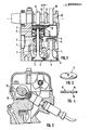
- the drawing shows the arrangement of a hanging valve controlled above.
- This consists of the valve tappet 1 with the valve plate 3 interacting with the valve seat 2.
- the tappet 1 is guided in a bush 4 which has a plate 5 on which the valve spring 6 is supported, the other end of which rests on the plate 7.
- the cam-side end of the valve tappet 1 is encompassed by a guide sleeve 8, the outer edge 9 of which extends beyond the surface 10 and serves to guide the valve adjusting plate 11, which rests freely rotatably on the surface 10 within the projecting edge 9.
- a number of cams 13 corresponding to the number of valves to be controlled are arranged, which act once on the valve setting plate 11 with each revolution of the shaft 12 and, via this and the guide sleeve 8, accelerate the valve tappet 1 and the valve disk 3 to the maximum and at retard the opposite movement accordingly, so that the valve plate 3 lifts off the valve seat 2 in a very short time and then comes back to the system.
- the valve adjusting plate 11 consists of a fired ceramic material, the surface 15 of which is ground, polished and / or lapped, so that the lowest possible amount of friction results between the cam 13 and the surface 15.
Landscapes
- Engineering & Computer Science (AREA)
- Mechanical Engineering (AREA)
- General Engineering & Computer Science (AREA)
- Chemical & Material Sciences (AREA)
- Ceramic Engineering (AREA)
- Combustion & Propulsion (AREA)
- Valve-Gear Or Valve Arrangements (AREA)
Applications Claiming Priority (2)
| Application Number | Priority Date | Filing Date | Title |
|---|---|---|---|
| DE3522403 | 1985-06-22 | ||
| DE19853522403 DE3522403A1 (de) | 1985-06-22 | 1985-06-22 | Ventileinstellplatte |
Publications (1)
| Publication Number | Publication Date |
|---|---|
| EP0209697A1 true EP0209697A1 (fr) | 1987-01-28 |
Family
ID=6273927
Family Applications (1)
| Application Number | Title | Priority Date | Filing Date |
|---|---|---|---|
| EP86107809A Withdrawn EP0209697A1 (fr) | 1985-06-22 | 1986-06-07 | Plaquette de réglage de jeu pour soupape |
Country Status (2)
| Country | Link |
|---|---|
| EP (1) | EP0209697A1 (fr) |
| DE (1) | DE3522403A1 (fr) |
Cited By (4)
| Publication number | Priority date | Publication date | Assignee | Title |
|---|---|---|---|---|
| EP0523691A3 (en) * | 1991-07-19 | 1993-03-03 | Sumitomo Electric Industries, Ltd. | Ceramic adjusting shim |
| EP0577877A1 (fr) * | 1991-09-04 | 1994-01-12 | Sumitomo Electric Industries, Ltd. | Cale de réglage |
| WO1997005367A1 (fr) * | 1995-07-27 | 1997-02-13 | INA Wälzlager Schaeffler oHG | Poussoir mecanique de cloche pour mecanisme de distribution d'un moteur a combustion interne |
| EP0953733A3 (fr) * | 1998-04-30 | 2000-08-02 | Sumitomo Electric Industries, Ltd. | Pièce de frottement pour un dispositif à frottement |
Citations (1)
| Publication number | Priority date | Publication date | Assignee | Title |
|---|---|---|---|---|
| DE2938283A1 (de) * | 1979-09-21 | 1981-04-02 | Audi Nsu Auto Union Ag, 7107 Neckarsulm | Vorrichtung zum steuern der gaswechselventile einer brennkraftmaschine |
Family Cites Families (2)
| Publication number | Priority date | Publication date | Assignee | Title |
|---|---|---|---|---|
| GB1165446A (en) * | 1966-09-19 | 1969-10-01 | Fiat Spa | Valve Tappet |
| AU1797383A (en) * | 1982-09-30 | 1984-04-05 | Stanadyne Inc. | Tappet with ceramic camface |
-
1985
- 1985-06-22 DE DE19853522403 patent/DE3522403A1/de not_active Withdrawn
-
1986
- 1986-06-07 EP EP86107809A patent/EP0209697A1/fr not_active Withdrawn
Patent Citations (1)
| Publication number | Priority date | Publication date | Assignee | Title |
|---|---|---|---|---|
| DE2938283A1 (de) * | 1979-09-21 | 1981-04-02 | Audi Nsu Auto Union Ag, 7107 Neckarsulm | Vorrichtung zum steuern der gaswechselventile einer brennkraftmaschine |
Non-Patent Citations (3)
| Title |
|---|
| AUTOMOTIVE ENGINEERING, Band 92, Nr. 12, Dezember 1984, Seiten 77-81, Warrendale, Pennsylvania, US; D. SCOTT et al.: "Advanced ceramic bids for engine parts" * |
| MOTORTECHNISCHE ZEITSCHRIFT, Band 44, Nr. 6, Juni 1983, Seiten 225-229, Stuttgart, DE; P. WALZER et al.: "Hochtemperaturkeramik für Verbrennungskraftmaschinen" * |
| MOTORTECHNISCHE ZEITSCHRIFT, Band 46, Nr. 5, Mai 1985, Seiten 155-160, Stuttgart, DE; P. WALZER et al.: "Alternative Werkstoffe für Automobilantriebe" * |
Cited By (6)
| Publication number | Priority date | Publication date | Assignee | Title |
|---|---|---|---|---|
| EP0523691A3 (en) * | 1991-07-19 | 1993-03-03 | Sumitomo Electric Industries, Ltd. | Ceramic adjusting shim |
| EP0577877A1 (fr) * | 1991-09-04 | 1994-01-12 | Sumitomo Electric Industries, Ltd. | Cale de réglage |
| WO1997005367A1 (fr) * | 1995-07-27 | 1997-02-13 | INA Wälzlager Schaeffler oHG | Poussoir mecanique de cloche pour mecanisme de distribution d'un moteur a combustion interne |
| US5884595A (en) * | 1995-07-27 | 1999-03-23 | Ina Walzlager Schaeffler Ohg | Mechanical cup pushrod for an internal combustion engine's valve gear |
| EP0953733A3 (fr) * | 1998-04-30 | 2000-08-02 | Sumitomo Electric Industries, Ltd. | Pièce de frottement pour un dispositif à frottement |
| US6220757B1 (en) | 1998-04-30 | 2001-04-24 | Sumitomo Electric Industries, Ltd. | Sliding part for a sliding mechanism |
Also Published As
| Publication number | Publication date |
|---|---|
| DE3522403A1 (de) | 1987-01-02 |
Similar Documents
| Publication | Publication Date | Title |
|---|---|---|
| DE3205878A1 (de) | Stoessel fuer einen verbrennungsmotor | |
| DE2814096C2 (fr) | ||
| DE19908286B4 (de) | Variable Ventilsteuerung für Brennkraftmaschinen | |
| DE2101665B2 (de) | Ventilsteuerung fuer brennkraftmaschinen | |
| DE3424773A1 (de) | Brennkraftmaschine mit einer einzigen obenliegenden nockenwelle | |
| DE69016706T2 (de) | Vorrichtung zur Veränderung der Ventilsteuerzeit und des Ventilhubes. | |
| DE69016223T2 (de) | Ventiltriebvorrichtung mit elektromagnetischer Kraft. | |
| EP1561011B1 (fr) | Systeme d'actionneur oscillant servant a commander la levee d'une soupape de changement des gaz dans la culasse d'un moteur a combustion | |
| EP0155261B2 (fr) | Distribution à soupape pour moteur à combustion interne | |
| WO2000004281A1 (fr) | Entrainement electromagnetique de soupape | |
| DE69303740T2 (de) | Ventilantrieb für eine Brennkraftmaschine | |
| DE3929641A1 (de) | Drehventil-betaetigungsvorrichtung | |
| DE60305981T2 (de) | Ventilbetätigungsvorrichtung für variable ventilsteuerung für gaswechselventile einer brennkraftmaschine | |
| EP0209697A1 (fr) | Plaquette de réglage de jeu pour soupape | |
| DE4330913A1 (de) | Ventiltrieb für Brennkraftmaschinen | |
| DE102004022832A1 (de) | Ventiltrieb für eine Brennkraftmaschine | |
| DE3234639C2 (fr) | ||
| EP1716318A1 (fr) | Mecanisme de commande de soupape a levee variable pour un moteur a combustion interne | |
| EP1375843B1 (fr) | Moteur à combustion interne | |
| DE102019133517A1 (de) | Ventilbrücke für den Ventiltrieb einer Brennkraftmaschine | |
| WO1992012333A1 (fr) | Dispositif pour l'actionnement des soupapes d'un moteur alternatif | |
| DE3503740A1 (de) | Vorrichtung zur veraenderung der steuerzeiten bei ventilgesteuerten verbrennungsmotoren | |
| DE69000606T2 (de) | Verbessertes elektromagnetisches ventil, insbesondere fuer einspritzpumpe. | |
| DE10237104A1 (de) | Ventiltrieb für eine Hubkolben-Brennkraftmaschine | |
| DE3814262A1 (de) | Brennkraftmaschine mit keramikventilen |
Legal Events
| Date | Code | Title | Description |
|---|---|---|---|
| PUAI | Public reference made under article 153(3) epc to a published international application that has entered the european phase |
Free format text: ORIGINAL CODE: 0009012 |
|
| AK | Designated contracting states |
Kind code of ref document: A1 Designated state(s): DE FR IT SE |
|
| 17P | Request for examination filed |
Effective date: 19870122 |
|
| 17Q | First examination report despatched |
Effective date: 19871028 |
|
| STAA | Information on the status of an ep patent application or granted ep patent |
Free format text: STATUS: THE APPLICATION HAS BEEN WITHDRAWN |
|
| 18W | Application withdrawn |
Withdrawal date: 19881130 |
|
| RIN1 | Information on inventor provided before grant (corrected) |
Inventor name: LOOS, MANFRED |