EP0209873A2 - Hydratationsbehälter - Google Patents
Hydratationsbehälter Download PDFInfo
- Publication number
- EP0209873A2 EP0209873A2 EP86109951A EP86109951A EP0209873A2 EP 0209873 A2 EP0209873 A2 EP 0209873A2 EP 86109951 A EP86109951 A EP 86109951A EP 86109951 A EP86109951 A EP 86109951A EP 0209873 A2 EP0209873 A2 EP 0209873A2
- Authority
- EP
- European Patent Office
- Prior art keywords
- container
- members
- compartment
- projections
- floor
- Prior art date
- Legal status (The legal status is an assumption and is not a legal conclusion. Google has not performed a legal analysis and makes no representation as to the accuracy of the status listed.)
- Granted
Links
Images


Classifications
-
- B—PERFORMING OPERATIONS; TRANSPORTING
- B01—PHYSICAL OR CHEMICAL PROCESSES OR APPARATUS IN GENERAL
- B01L—CHEMICAL OR PHYSICAL LABORATORY APPARATUS FOR GENERAL USE
- B01L3/00—Containers or dishes for laboratory use, e.g. laboratory glassware; Droppers
- B01L3/50—Containers for the purpose of retaining a material to be analysed, e.g. test tubes
- B01L3/508—Rigid containers without fluid transport within
- B01L3/5085—Rigid containers without fluid transport within for multiple samples, e.g. microtitration plates
-
- B—PERFORMING OPERATIONS; TRANSPORTING
- B01—PHYSICAL OR CHEMICAL PROCESSES OR APPARATUS IN GENERAL
- B01F—MIXING, e.g. DISSOLVING, EMULSIFYING OR DISPERSING
- B01F2101/00—Mixing characterised by the nature of the mixed materials or by the application field
- B01F2101/23—Mixing of laboratory samples e.g. in preparation of analysing or testing properties of materials
-
- B—PERFORMING OPERATIONS; TRANSPORTING
- B01—PHYSICAL OR CHEMICAL PROCESSES OR APPARATUS IN GENERAL
- B01L—CHEMICAL OR PHYSICAL LABORATORY APPARATUS FOR GENERAL USE
- B01L2300/00—Additional constructional details
- B01L2300/06—Auxiliary integrated devices, integrated components
- B01L2300/0609—Holders integrated in container to position an object
-
- B—PERFORMING OPERATIONS; TRANSPORTING
- B01—PHYSICAL OR CHEMICAL PROCESSES OR APPARATUS IN GENERAL
- B01L—CHEMICAL OR PHYSICAL LABORATORY APPARATUS FOR GENERAL USE
- B01L2300/00—Additional constructional details
- B01L2300/08—Geometry, shape and general structure
- B01L2300/0848—Specific forms of parts of containers
- B01L2300/0858—Side walls
-
- B—PERFORMING OPERATIONS; TRANSPORTING
- B01—PHYSICAL OR CHEMICAL PROCESSES OR APPARATUS IN GENERAL
- B01L—CHEMICAL OR PHYSICAL LABORATORY APPARATUS FOR GENERAL USE
- B01L2400/00—Moving or stopping fluids
- B01L2400/08—Regulating or influencing the flow resistance
- B01L2400/084—Passive control of flow resistance
- B01L2400/086—Passive control of flow resistance using baffles or other fixed flow obstructions
-
- G—PHYSICS
- G01—MEASURING; TESTING
- G01N—INVESTIGATING OR ANALYSING MATERIALS BY DETERMINING THEIR CHEMICAL OR PHYSICAL PROPERTIES
- G01N35/00—Automatic analysis not limited to methods or materials provided for in any single one of groups G01N1/00 - G01N33/00; Handling materials therefor
- G01N35/02—Automatic analysis not limited to methods or materials provided for in any single one of groups G01N1/00 - G01N33/00; Handling materials therefor using a plurality of sample containers moved by a conveyor system past one or more treatment or analysis stations
- G01N35/04—Details of the conveyor system
- G01N2035/0401—Sample carriers, cuvettes or reaction vessels
- G01N2035/0429—Sample carriers adapted for special purposes
- G01N2035/0436—Sample carriers adapted for special purposes with pre-packaged reagents, i.e. test-packs
Definitions
- the present invention relates to a container configured to facilitate the dissolution or dispersion of tableted or partially emulsified material using ultrasonic energy.
- Such prolonged sonication may result in excess heating of the body of liquid in which the tablet is disposed.
- This excessive heating may be especially deleterious when the tableted material is being dissolved within a body of liquid (e.g.. a sample and/or reagent) that is used for the analysis of biological liquids.
- a container arrangement whereby tableted or partially emulsified material may be dissolved or dispersed expeditiously (i.e.. in less than one minute) by the application of ultrasonic energy from a point in the interior of the container.
- lid structure which is resealable to permit extended storage without evaporation and, simultaneously to accommodate mixing or sampling probes.
- Lid structures which realize these goals are available in the art. Exemplary of such devices is that disclosed in United States Patent 3,994,594 (Sandrock et al.). However, such lid structures are believed incompatible for use in an environment in which the mixing and/or sampling probe is other than a sharp implement.
- a lid structure which minimizes vapor transmission from compartment to compartment, thus minimizing contamination of the contents of one compartment by the contents of another compartment.
- the source of sonic energy used for dissolving tableted material is a device known as an ultrasonic horn.
- the horn is a relatively elongated member which vibrates at an ultrasonic frequency as a result of a conversion of an electrical excitation signal into a mechanical vibration.
- Ultrasonic horns may be provided with a bore through which a liquid may be flowed through the horn and out of the tip. This structure allows injection of one liquid into another, as in emulsion formulation, misting or fogging.
- Such ultrasonic horns are produced by, among others. Heat Systems - Ultrasonics Inc., Farmingdale. New York.
- horn structures which operate as atomizers by pumping a liquid from a reservoir by the pumping action generated as a result of an asymmetric sound field forming bubbles in the bore.
- Exemplary of this type of device is that shown in the Article by Lierke. "Ultrasonic Atomizer Incorporating A Self-Acting Liquid Supply”. 5 Ultrasonics. 214 (1967).
- the present invention relates to a container having a hydration compartment defined therein.
- the container may receive a hydrating liquid and one or more tablets of solid material to be dissolved or dispersed therein.
- the container has an array of sonication-improving projections mounted therein which cooperate to define a tablet-receiving recess.
- the projections are spaced from each other to provide recirculating channels which communicate with both the tablet-receiving recess and the remainder of the volume of the container such that, in use, the projections act to confine a tableted material within a relatively high ultrasonic energy zone and simultaneously permit a flow of hydrating liquid from the high energy zone through the channels thereby to rapidly effect the dissolution of the tableted material.
- each of the containers 10A through 10F is provider with an array of the preferred form of sonication-improving projections generally indicated by reference character 30 provided in accordance with the present invention.
- the container strip 12 may be fabricated in any convenient manner.
- the container strip 12 includes a rigid peripheral band 14 formed of a suitable material, such as an inert plastic.
- the band 14 is either joined to or formed integrally with each of the containers 10 such that, in the preferred case, the container strip 12 generally tapers in a substantially elongated wedge-like manner from a first edge 16L toward a second edge 16R.
- This wedge-shaped plan profile for the container strip 12 facilitates the mounting of a plurality of such strips in a circumferentially adjacent, generally radially extending relationship across a rotatable reagent carrying plate such as that disclosed in the analysis instrument disclosed and claimed in copending application titled Analysis Instrument Having Heat-Formed Analysis Cuvettes.
- Each of the containers 10, whether arranged singularly or in a container strip 12, in the embodiment shown, is formed of a suitable inert plastic material and includes a compartment defined by generally opposed pairs of generally parallel and integrally formed sidewalls 1BA, 18B and end walls 20A, 20B.
- the upper surfaces of the sidewalls 18A and 1 8 B and endwalls 20A and 20B (together with the upper surface of the band 14 in the vicinity thereof) register to define a substantially planar sealing surface 22 peripherally surrounding the open upper end of the container 10.
- the compartment of the container 10 is closed by a downwardly sloping inverted pyramidal floor 24 ( Figure 2).
- Figure 1 the sidewalls 18A, 18B of each container 10 are joined to the peripheral band 14.
- the endwall 20A of the container 10A and the endwall 20B of the container 10F are likewise connected to the band 14.
- the band 14 extends slightly below the lower ends of the containers 10 and thus define a support strut 26 whereby the container strip 12 may be set on a suitable work surface.
- the container 10 were used singly any convenient arrangement may be used to support the container on a work surface.
- the containers 10A, 10B, 10C and 10D are arranged in a substantially square configuration while the containers 10E and 10F are configured in a more rectangular configuration.
- individual containers may be defined to be other than rectangular or square in plan and be provided with other than a downwardly sloping floor 24 and yet remain within the contemplation of the present invention.
- Adjacent endwalls 20A, 20B of adjacent containers 10 are spaced from each other by a predetermined gap 28 to enhance the thermal and vapor isolation of each of the containers 10.
- the container strip 12 is formed by injection molding from a polyallomer material. Of course, other manufacturing techniques and materials of construction may ba utilized and remain within the contemplation of the present invention.
- each of the containers 10 carries an array of mutually spaced sonication improving projections 30.
- the individual projections 30 are spaced from each other to define channels 32 therebetween.
- the projections 30 take the form of a set of substantially finger-like members 36, 36 ' extending vertically upwardly in axially parallel relationship from the floor 24 of each container 10. Selected ones 36 of the finger-like members project upwardly from the floor 24 for a distance greater than the others 36' of the members of the set. Such a relationship thereby defines a tablet-receiving recess 38 disposed generally centrally within the container 10.
- the sonication improving projections 30 may be disposed in any convenient orientation or at any convenient location within the container 10.
- the finger-like members 36. 36' are used to define the projections 30, such members may be inclined with respect to the vertical axis of the container 10 and may be mounted to the sidewalls 18A. 18B and/or the endwalls 20A. 20B in addition to or in place of their mounting on the floor 24.
- planar members 40 extend diagonally outwardly from the corners of the container 10 to assist in guiding of the circulating hydrating liquid. As seen the side surfaces of the planar members 40 lie substantially perpendicularly to the floor 24.
- FIGS 3A through 3D depict plan views of individual containers 10 and illustrate the form and arrangement with vertical side surfaces of alternate embodiments of the sonication improving projections.
- the projections 30 are in the form of plate-like members 42 generally similar to the members 40 shown in Figures 1 and 2. Some of the plates 42 extend inwardly from the corners of the container 10 while others 42' extend inwardly from the container from the sidewalls 18 and endwalls 20 thereof. The plates 42, 42' are thus respectively oriented substantially along diagonals and transverses of the container 10. The inner ends of the plates 42, 42' preferably, but not necessarily, extend substantially vertically of the container 10 from the floor 24 of the container.
- the lower edges of the plates 42, 42' may integrate with the floor 24, if desired.
- the vertically oriented inner ends of the plates 42, 42' cooperate to define on the interior of the container the centrally located tablet-receiving recess 38.
- the spaces between the plates 42. 42' define the channels 32 through which hydrated liquid may flow in a manner to be described.
- the projections 30 are in the form of inwardly directed pyramid structures 46, 46'.
- the pyramidal structures 46, 46' are each defined by faces 48, which are joined along an apex 50 that substantially align in the respective cases of the structures 46 and 46' with the diagonals and transverses of the container 10.
- the structures 46. 46' are thus mounted in positions analogous to the plates 42, 42' and are thus substantially diagonally and transversely disposed within the container 10.
- the spaces between the structures 46, 46' define the channels 32 for the purpose to be described.
- the floor 24 of the container 10 is provided with a central circular region 54 which is intersected by diagonal grooves 56 thereby to respectively define the tablet-receiving recess 38 and the channels 32.
- the floor 24 is substantially flat.
- the projections 30 are thus defined as those portions of the material of the container 10 between the grooves 56.
- the central region 54 again defines the recess 38.
- the region 54 is interrupted by a plurality of generally parallel grooves 58 which serve to define the channels 32.
- End grooves 60 are also provided.
- the projections 32 are defined as those portions of the material between the grooves 58. 60.
- a tableted material to be dissolved or dispersed is introduced into a hydrating liquid introduced within the container.
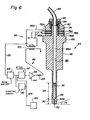
- Sonifying energy is provided from an ultrasonic transducer such as the device (discussed in connection with Figure 6) lowered into the container 10 through the open end thereof.
- Actuation of the ultrasonic transducer introduces ultrasonic energy and directs the same substantially axially of the container to encompass the tablet-receiving recess 38.
- the ultrasonic energy may be applied continuously or in bursts, with a relatively constant or varying frequency.
- the tablet (or plurality of tablets) of material to be dissolved or dispersed into the liquid in the container migrates toward and is confined within tablet receiving recess 38.
- the structural relationship between the projections 30 serves to define a recess 38 which defines a relatively high ultrasonic energy region within the container in which the material to be dissolved is received and confined. Any entrapped air beneath the material to be dissolved and hydrating liquid flow is permitted from other regions on the interior volume of the container through the high energy sonication region and then outwardly through the channels 32 between the projections 30. It is believed that if the embodiment of the projections 30 shown in Figures 1 and 2, i.e.. the finger-like members, is used reflection of ultrasonic energy from the walls and floor of the container into the recess 38.
- any suitable projections disposed either on the floor and/or from the walls of the container which serve to define both a tablet-receiving recess and recirculating gaps to permit the circulation of hydrating liquid through the high energy zone act in use to enhance the application of ultrasonic energy to efficiently and expeditiously dissolve the tablet material.
- Any such structural combination which forms the relatively high energy tablet-receiving recess and defines a relatively high ultrasonic energy zone coupled with and communicating recirculating channels lies within the contemplation of the present invention.
- the body or horn portion 66 of the transducer 64 is an elongated axial member extending from an enlarged head portion 68 to a beveled tip 70.
- the tip 70 defines an angle 72 measured with respect to a reference line perpendicular to the axis of the bore within the range from 0° to 45°, more particularly from 30° to 45°, and precisely 30°.
- An axially projecting threaded boss 74 extends upwardly from the head 68.
- a pair of piezoelectric crystals 76A, 76B with associated electrodes 78A, 78B are received about the boss 74.
- Leads 80A, 80B extend from the electrodes 78A. 78B, respectively.
- the crystals 76 are held in place against the head 68 by a backpiece 82.
- a nut 84 threads onto the boss 74 and clamps the assembly together.
- a tubing connector 85 is threadedly received onto the upper portion of the threads of the nut 84.
- a tube 86 mounted within the connector 84 may thus be quickly and easily interconnected with the ultrasonic transducer 64.
- a bore 88 extends centrally and axially through the transducer 66 where it communicates with the end of the tube 86.
- the internal diameters of the tube 86 and the upper portion 88A of the bore 88 are substantially equal.
- the relatively larger diameter portion 88A extends over substantially all of the length of the transducer 66.
- Disposed within a predetermined distance 90 of the end of the horn 66 is an inwardly tapering beveled shoulder 92.
- the presence of the shoulder 92 narrows the bore 88 to a lesser diameter portion 88B.
- the shoulder 92 is located within the predetermined close distance 90 from the antinode (or the tip of the beveled end 66) of the vibrating horn 62.
- the tube 86 is connected to suitable aspirating and hydrating sources whereby hydrating liquid may be dispensed from and aspirated into the transducer 64.
- suitable aspirating and hydrating sources whereby hydrating liquid may be dispensed from and aspirated into the transducer 64.
- the bore 88 is cleaned by the microstreaming and cavitating action produced by the abutment of the shoulder 92 against a continuous column 93 of liquid extending a predetermined distance 94 into the enlarged portion 88A of the bore.
- An ultrasonic horn assembly 64 as shown in Figure 6 is adapted to precisely dispense and aspirate liquid into and from a container 10 and to provide the sonic energy necessary to dissolve a tablet or partially emulsified material.
- the horn assembly 64 can also be used to mix together at least two liquid materials. Due to the provision of the shoulder 92 the cleaning action generated within the continuous column 94 of liquid is generated which prevents accumulation of matter on the walls of the bore and thus minimizes carryover. It is also believed that the cleaning action extends into liquid within the tube 86, thus minimizing carryover at the interface between the horn and the tube.
- the horn assembly 64 may also form a part of an apparatus for detecting the presence of a solid interface (e.g., a lid) or a liquid interface (e.g., the surface of a liquid reagent or a liquid sample.
- a solid interface e.g., a lid
- a liquid interface e.g., the surface of a liquid reagent or a liquid sample.
- the leads 80A. 80B are applied to a self resonant power supply network 95 such as that disclosed in United States Patent 4,445,064, which patent is incorporated by reference herein.
- the network 95 includes a motional bridge circuit 96 for generating feedback signals proportional to the vibration of the ultrasonic horn assembly 64 which is modified by means of an active filter 97 in the feedback circuit which is coupled to a starting circuit 98 that raises the Q of the active filter when a signal is not present in the feedback loop to change the active filter from a mode suppressant to a self-oscillating state.
- the horn assembly 64 is operated in a motional bridge circuit 96 which, in turn, is coupled to the output of constant gain power amplifier 99 via a transformer 100.
- the motional bridge circuit 96 not only serves to apply excitation power to the horn 64, but more importantly, it produces a sinusoidal feedback control voltage on line 101 that (1) corresponds directly with transducer tip frequency, amplitude and phase and (2) remains independent of nonreactive load changes on the transducer.
- Line 101 connects the motional bridge circuit 96 to the input of the all pass phase shifter circuit 102.
- Connected to the output of phase shifter 102 is the active filter circuit 97 and the starting circuit 98 to make filter 97 self oscillating.
- Active filter 97 is connected to the input of power amplifier 99 whose output is connected to transformer 100 through inductance 103 to drive motional bridge circuit 96.
- Feedback control voltage of line 101 is the input to phase shifter circuit 102 which is used to tune the phasing of the input sinusoidal signal in such a predetermined amount and direction that the transducer vibrations are constrained to remain in the parallel resonance condition. It is important to note that only the phasing of the feedback signal, and not amplitude, is adjusted so as to not disturb loop gain and the mode suppression function of succeeding active filter circuit 97.
- Phase shifter circuit 102 is configured as a first-order all pass network with variable phase shift. Its output is a replica (except for phase) of the input AC feedback signal from motional bridge circuit 96.
- Active filter 97 is a dual-purpose second-order 0-controlled band pass filter.
- the primary purpose of filter 97 is to prevent the power supply from driving the transducer system "out of band" into vibrational modes that have not been selected for use. Used in this way, it is called a mode suppressant filter.
- the secondary purpose of filter 97 does not appear unless the feedback signal on line 101 is lost completely. such as at startup. In this event, starting circuit 98 which monitors the output signal from phase-shifter circuit 102, causes the Q of active filter circuit 97 to increase to the point where filter circuit 97 brakes into oscillation.
- Circuit Q is defined as the ratio of resonant frequency (W o ) to -3 dB bandwidth (BW) or
- the frequency of oscillation is made to be coincident with the preselected natural parallel resonant frequency of the transducer system.
- the oscillator mode afforded by active filter 97 remains as long as needed to re-establish the feedback control signal on line 101 from motional bridge circuit 96.
- a voltage (on the order of seventy volts. RM S) is applied to the horn 64 which is sufficient to just drive the unloaded horn 64 to vibrate at its resonant frequency.
- the horn operates in the frequency range from 20 to 100 kHz., more particularly 40 to 60 kHz, and specifically at 50 kHz.
- the tip 70 of the horn 64 encounters the solid or liquid interface the horn becomes loaded and the horn no longer resonates.
- the signal in the line 101 is thus lost.
- the loss of the feedback signal causes the starting circuit 98 to produce a signal on the line 104 to a device 105. e.g., a digital computer.
- a device 105 e.g., a digital computer.
- Each of the containers 10 in the multi-container strip 12 shown in Figure 1 may be closed by a lid structure L in accordance with the present invention.
- the lid structure includes a first, lower, support sheet 106 having an array of spaced receptacles 107 therein.
- Each receptacle 107 occupies a perimetric configuration corresponding to the shape of the open end of the container 10 with which it is associated.
- a second, upper, cover sheet 108 overlies the lower sheet 106.
- the sheet 108 is joined to the sheet 106 along those interfacing portions thereof to thus define a substantially enclosed volume 110 within each receptacle 107.
- the sheets 106 and 108 are joined by any suitable expedient and define a peripheral flange region 112 entirely surrounding the enclosed volume 110.
- Disposed within each of the volumes 110 is a thermoplastic elastomer pad 112 such as that sold by West Company of Phoenixville. Pennsylvania, under formulation number 8553-3-5-1.
- the pad 114 is received within each enclosed volume 110 and is sized such that a gap 116 is defined between the walls of the receptacle and the undersurface of the upper sheet 108.
- the lid structure L in the above-described assembled relationship is arranged to overlie each container 10 in the strip 12.
- the undersurface of the peripheral flange region 112 defined by the jointure of the sheets 106, 108 is heat sealed or otherwise attached to the sealing surface 22 of the compartments 12.
- the containers are each closed by an impermeable seal which serves to form an evaporation barrier for the contents of the compartment and to isolate the containers against vapor cross contamination.
- the sheet 108 is, in the preferred embodiment formed of a laminate of (i) an outer polyester film, such as that sold by E. I. du Pont de Nemours and Company under the trademark MYLAR. (ii) a polyvinylidene chloride coating such as that sold by Dow Chemicals Co. under the trademark SARAN, and (iii) an outer barrier sheet of polyethylene. The polyethylene sheet interfaces against the lower sheet and is joined thereto. Of course, any other suitable materials may be used for the sheets 106 and 108.
- the top sheet 108 forms a vapor barrier to enhance the shelf life of a container covered by the lid L.
- the pad 116 may also be implemented using any stretchable. resealable material, such as silicone rubber or natural rubber.
- the lid is arranged such that the pad 114 projects downwardly into the container. However, the reverse is also possible, i.e., where pad 114 is disposed above the container. If only a single container is being covered the lid may be implemented using a single sheet with a pad secured thereto. Either surface of the sheet may be attached to the container whereby the pad projects into or lies above the container.
- the pad 114 may be provided with a slit 120 which defines an entry and exit path whereby an ultrasonic horn. e.g. the horn 64, may be introduced into the container 10.
- the elastomeric material of the pad 114 is selected so that the pad self-heals as the horn is withdrawn, thereby maintaining a substantially integral evaporation barrier over the container.
- the pad 114 self-heals even for relative large diameter probes (i.e., on the order of .125 inches).
- the lid structure L is useful in conjunction with relatively blunt probes.
- the material of the pad 114 performs a wiping action on the exterior of the horn as the horn is inserted or withdrawn. This wiping action prevents cross contamination. It has been found that the provision of the gap between the pad and the receptacle facilitates the entry of the probe or horn into the container.
Landscapes
- Health & Medical Sciences (AREA)
- Chemical & Material Sciences (AREA)
- Chemical Kinetics & Catalysis (AREA)
- General Health & Medical Sciences (AREA)
- Hematology (AREA)
- Clinical Laboratory Science (AREA)
- Analytical Chemistry (AREA)
- Catching Or Destruction (AREA)
- Mixers With Rotating Receptacles And Mixers With Vibration Mechanisms (AREA)
- Closures For Containers (AREA)
- Medical Preparation Storing Or Oral Administration Devices (AREA)
- Lining Or Joining Of Plastics Or The Like (AREA)
- Separation Using Semi-Permeable Membranes (AREA)
- Medicinal Preparation (AREA)
Priority Applications (1)
| Application Number | Priority Date | Filing Date | Title |
|---|---|---|---|
| AT86109951T ATE66832T1 (de) | 1985-07-22 | 1986-07-19 | Hydratationsbehaelter. |
Applications Claiming Priority (2)
| Application Number | Priority Date | Filing Date | Title |
|---|---|---|---|
| US06/757,576 US4720374A (en) | 1985-07-22 | 1985-07-22 | Container having a sonication compartment |
| US757576 | 1985-07-22 |
Publications (3)
| Publication Number | Publication Date |
|---|---|
| EP0209873A2 true EP0209873A2 (de) | 1987-01-28 |
| EP0209873A3 EP0209873A3 (en) | 1988-07-27 |
| EP0209873B1 EP0209873B1 (de) | 1991-09-04 |
Family
ID=25048363
Family Applications (1)
| Application Number | Title | Priority Date | Filing Date |
|---|---|---|---|
| EP86109951A Expired EP0209873B1 (de) | 1985-07-22 | 1986-07-19 | Hydratationsbehälter |
Country Status (8)
| Country | Link |
|---|---|
| US (1) | US4720374A (de) |
| EP (1) | EP0209873B1 (de) |
| JP (1) | JPS6227031A (de) |
| AT (1) | ATE66832T1 (de) |
| CA (1) | CA1275075A (de) |
| DE (1) | DE3681218D1 (de) |
| DK (1) | DK345786D0 (de) |
| GR (1) | GR861903B (de) |
Cited By (3)
| Publication number | Priority date | Publication date | Assignee | Title |
|---|---|---|---|---|
| EP0355802A3 (de) * | 1988-08-26 | 1991-10-16 | E.I. Du Pont De Nemours And Company | Wirbelbehälter für Flüssigkeiten |
| EP0555842A1 (de) * | 1992-02-14 | 1993-08-18 | Japan Science, Inc. | Verfahren zum Auflösen von biologischem Gewebe |
| WO2010055337A1 (en) * | 2008-11-11 | 2010-05-20 | Univeristy Of Hull | Tablet processing unit |
Families Citing this family (72)
| Publication number | Priority date | Publication date | Assignee | Title |
|---|---|---|---|---|
| DE3641093A1 (de) * | 1986-12-02 | 1988-06-16 | Hoechst Ag | Reaktionsgefaess |
| NZ226230A (en) * | 1987-09-18 | 1991-01-29 | Schering Agrochemicals Ltd | Implant gun for use with cartridge of strip form |
| AU616905B2 (en) * | 1987-09-21 | 1991-11-14 | Sanofi Sante Nutrition Animale Sa | Cartridge |
| AU104764S (en) | 1987-09-21 | 1989-08-22 | Sanofi Sante Nutrition Animale S A | Implant gun |
| US4935274A (en) * | 1988-08-26 | 1990-06-19 | E. I. Du Pont De Nemours And Company | Lid structure |
| US5120503A (en) * | 1989-07-14 | 1992-06-09 | Eastman Kodak Company | Extracting device for extracting antigens |
| US20060013729A1 (en) * | 1991-02-14 | 2006-01-19 | Glen Carey | Fluid handling apparatus for an automated analyzer |
| US6436349B1 (en) * | 1991-03-04 | 2002-08-20 | Bayer Corporation | Fluid handling apparatus for an automated analyzer |
| US6498037B1 (en) * | 1991-03-04 | 2002-12-24 | Bayer Corporation | Method of handling reagents in a random access protocol |
| US5876671A (en) * | 1993-03-24 | 1999-03-02 | The Regents Of The University Of California Office Of Technology Transfer | Sonication standard laboratory module |
| US5529753A (en) * | 1993-07-09 | 1996-06-25 | Dade International Inc. | System for ultrasonic energy coupling by irrigation |
| US5888826A (en) * | 1994-06-30 | 1999-03-30 | Dade Behring Inc. | Combination reagent holding and test device |
| EP2275821A1 (de) | 1995-07-31 | 2011-01-19 | Precision System Science Co., Ltd | Behälter |
| US5958228A (en) * | 1995-08-24 | 1999-09-28 | Nippondenso Co., Ltd. | Method of and an apparatus for producing a mineral water |
| US6048734A (en) | 1995-09-15 | 2000-04-11 | The Regents Of The University Of Michigan | Thermal microvalves in a fluid flow method |
| DE19836110C2 (de) * | 1998-08-10 | 2002-07-11 | Jandratek Gmbh | Sensorvorrichtung mit einer Mischeinrichtung |
| US6228273B1 (en) * | 1998-08-21 | 2001-05-08 | Hammonds Technical Services, Inc. | Apparatus and method for control of rate of dissolution of solid chemical material into solution |
| AU8368501A (en) * | 2000-08-18 | 2002-02-25 | Liquitab Pty Ltd | Method and apparatus for dispensing medication |
| EP1311224A4 (de) * | 2000-08-18 | 2006-07-05 | Liquitab Pty Ltd | Methode und vorrichtung zur medizinverabreichung |
| US6692700B2 (en) * | 2001-02-14 | 2004-02-17 | Handylab, Inc. | Heat-reduction methods and systems related to microfluidic devices |
| US7323140B2 (en) * | 2001-03-28 | 2008-01-29 | Handylab, Inc. | Moving microdroplets in a microfluidic device |
| US6852287B2 (en) | 2001-09-12 | 2005-02-08 | Handylab, Inc. | Microfluidic devices having a reduced number of input and output connections |
| US7010391B2 (en) | 2001-03-28 | 2006-03-07 | Handylab, Inc. | Methods and systems for control of microfluidic devices |
| US7829025B2 (en) | 2001-03-28 | 2010-11-09 | Venture Lending & Leasing Iv, Inc. | Systems and methods for thermal actuation of microfluidic devices |
| US8895311B1 (en) | 2001-03-28 | 2014-11-25 | Handylab, Inc. | Methods and systems for control of general purpose microfluidic devices |
| GB2374560B (en) * | 2001-04-17 | 2005-04-06 | Rawson Francis F H | Processing vessel |
| US20020159917A1 (en) * | 2001-04-27 | 2002-10-31 | Swart Sally Kay | System and method for cleaning, high level disinfection, or sterilization of medical or dental instruments or devices |
| US6800491B2 (en) | 2001-06-08 | 2004-10-05 | Nalge Nunc International Corporation | Robotic reservoir without liquid hangup |
| US7378281B2 (en) * | 2002-03-08 | 2008-05-27 | The United States Of America As Represented By The Secretary Of The Navy | Process to measure PPB levels of dissolved copper in jet fuels and other non-aqueous fluids using a colorimetric process |
| US6808304B2 (en) * | 2002-08-27 | 2004-10-26 | Dade Behring Inc. | Method for mixing liquid samples using a linear oscillation stroke |
| US6991764B2 (en) * | 2002-12-13 | 2006-01-31 | Dade Behring Inc. | Method for replacing used reaction cuvettes in an automatic analyzer depending upon next scheduled assay |
| EP1654066B1 (de) | 2003-07-31 | 2014-11-12 | Handylab, Inc. | Verarbeitung von teilchenhaltigen proben |
| CN100515881C (zh) * | 2003-09-09 | 2009-07-22 | 未来技术(R&D)有限公司 | 分发容器和分发容器的覆盖膜 |
| US8852862B2 (en) | 2004-05-03 | 2014-10-07 | Handylab, Inc. | Method for processing polynucleotide-containing samples |
| EP2345739B8 (de) * | 2004-05-03 | 2016-12-07 | Handylab, Inc. | Mikrofluidische Vorrichtung zur Verarbeitung polynukleotidhaltiger Proben |
| US7258480B2 (en) * | 2005-01-10 | 2007-08-21 | Dade Behring Inc. | Apparatus for mixing liquid samples using a two dimensional stirring pattern |
| DK2001990T3 (en) | 2006-03-24 | 2016-10-03 | Handylab Inc | Integrated microfluidic sample processing system and method for its use |
| US11806718B2 (en) | 2006-03-24 | 2023-11-07 | Handylab, Inc. | Fluorescence detector for microfluidic diagnostic system |
| US8088616B2 (en) | 2006-03-24 | 2012-01-03 | Handylab, Inc. | Heater unit for microfluidic diagnostic system |
| US7998708B2 (en) | 2006-03-24 | 2011-08-16 | Handylab, Inc. | Microfluidic system for amplifying and detecting polynucleotides in parallel |
| US10900066B2 (en) | 2006-03-24 | 2021-01-26 | Handylab, Inc. | Microfluidic system for amplifying and detecting polynucleotides in parallel |
| WO2008061165A2 (en) | 2006-11-14 | 2008-05-22 | Handylab, Inc. | Microfluidic cartridge and method of making same |
| WO2008060604A2 (en) | 2006-11-14 | 2008-05-22 | Handylab, Inc. | Microfluidic system for amplifying and detecting polynucleotides in parallel |
| US8105783B2 (en) | 2007-07-13 | 2012-01-31 | Handylab, Inc. | Microfluidic cartridge |
| US8182763B2 (en) | 2007-07-13 | 2012-05-22 | Handylab, Inc. | Rack for sample tubes and reagent holders |
| US8287820B2 (en) | 2007-07-13 | 2012-10-16 | Handylab, Inc. | Automated pipetting apparatus having a combined liquid pump and pipette head system |
| USD621060S1 (en) | 2008-07-14 | 2010-08-03 | Handylab, Inc. | Microfluidic cartridge |
| US9618139B2 (en) | 2007-07-13 | 2017-04-11 | Handylab, Inc. | Integrated heater and magnetic separator |
| US8133671B2 (en) * | 2007-07-13 | 2012-03-13 | Handylab, Inc. | Integrated apparatus for performing nucleic acid extraction and diagnostic testing on multiple biological samples |
| US9186677B2 (en) | 2007-07-13 | 2015-11-17 | Handylab, Inc. | Integrated apparatus for performing nucleic acid extraction and diagnostic testing on multiple biological samples |
| US8324372B2 (en) * | 2007-07-13 | 2012-12-04 | Handylab, Inc. | Polynucleotide capture materials, and methods of using same |
| US20090136385A1 (en) * | 2007-07-13 | 2009-05-28 | Handylab, Inc. | Reagent Tube |
| US20100009351A1 (en) * | 2008-07-11 | 2010-01-14 | Handylab, Inc. | Polynucleotide Capture Materials, and Method of Using Same |
| USD618820S1 (en) | 2008-07-11 | 2010-06-29 | Handylab, Inc. | Reagent holder |
| USD787087S1 (en) | 2008-07-14 | 2017-05-16 | Handylab, Inc. | Housing |
| TWI429475B (zh) * | 2009-10-30 | 2014-03-11 | Rbc Bioscience Corp | 一體式反應匣 |
| GB201101488D0 (en) | 2011-01-28 | 2011-03-16 | Ge Healthcare Ltd | Container storing freeze dried biological sample |
| EP2697657B8 (de) | 2011-04-15 | 2017-08-16 | Becton, Dickinson and Company | Mikrofluidischer abtastender echtzeit-thermocycler und verfahren zur optischen detektion mittels synchronisierter thermozyklierung und abtastung |
| USD692162S1 (en) | 2011-09-30 | 2013-10-22 | Becton, Dickinson And Company | Single piece reagent holder |
| DK3273253T3 (da) | 2011-09-30 | 2020-10-12 | Becton Dickinson Co | Forenet reagensstrimmel |
| EP2773892B1 (de) | 2011-11-04 | 2020-10-07 | Handylab, Inc. | Vorrichtung zur vorbereitung von polynukleotidproben |
| DK2810080T3 (da) | 2012-02-03 | 2024-06-17 | Becton Dickinson Co | Eksterne filer til fordeling af molekylære diagnostiske tests og bestemmelse af kompatabilitet imellem tests |
| USD978375S1 (en) | 2013-03-13 | 2023-02-14 | Abbott Laboratories | Reagent container |
| US10058866B2 (en) | 2013-03-13 | 2018-08-28 | Abbott Laboratories | Methods and apparatus to mitigate bubble formation in a liquid |
| US9535082B2 (en) | 2013-03-13 | 2017-01-03 | Abbott Laboratories | Methods and apparatus to agitate a liquid |
| USD962471S1 (en) | 2013-03-13 | 2022-08-30 | Abbott Laboratories | Reagent container |
| EP2979878B1 (de) | 2013-03-29 | 2020-09-02 | Konica Minolta, Inc. | Bilderzeugungsvorrichtung |
| JP6637901B2 (ja) | 2014-11-21 | 2020-01-29 | 積水メディカル株式会社 | 検体希釈用容器 |
| EP3442705A1 (de) | 2016-04-15 | 2019-02-20 | The Moorhead Group | Bohrlochplatte |
| US11135591B1 (en) * | 2020-11-17 | 2021-10-05 | Aid Genomics Ltd | Test tube with an internal member |
| US11285485B1 (en) | 2020-11-17 | 2022-03-29 | Aid Genomics Ltd | Test tube with an internal member and test tube with a narrowed region at its closed end |
| CN114588818B (zh) * | 2021-12-27 | 2023-10-13 | 杭州康大晨星医学科技有限公司 | 一种试剂生产用匀浆装置 |
Family Cites Families (23)
| Publication number | Priority date | Publication date | Assignee | Title |
|---|---|---|---|---|
| US1353166A (en) * | 1919-02-21 | 1920-09-21 | Johnson John | Rapid dissolver |
| US3190731A (en) * | 1961-03-08 | 1965-06-22 | Technicon Instr | Sample-supply cups for analysis apparatus |
| DE1773584A1 (de) * | 1967-06-13 | 1973-01-04 | Xerox Corp | Reaktionsbehaelter |
| US3477821A (en) * | 1967-12-26 | 1969-11-11 | Xerox Corp | Chemical package |
| US3477822A (en) * | 1967-12-26 | 1969-11-11 | Xerox Corp | Chemical package |
| US3480399A (en) * | 1967-12-26 | 1969-11-25 | Xerox Corp | Chemical package |
| US3480398A (en) * | 1967-12-26 | 1969-11-25 | Xerox Corp | Chemical package |
| US3545934A (en) * | 1968-10-03 | 1970-12-08 | Xerox Corp | Chemical package |
| US3545935A (en) * | 1968-11-22 | 1970-12-08 | Xerox Corp | Disposable reaction container for an automatic chemical analyzer |
| US3582285A (en) * | 1970-03-19 | 1971-06-01 | Xerox Corp | Chemical package |
| US3582283A (en) * | 1970-03-25 | 1971-06-01 | Xerox Corp | Chemical package |
| US3691017A (en) * | 1970-05-06 | 1972-09-12 | Worthington Bio Chem Corp | Means and method for chemical analysis |
| US3788815A (en) * | 1972-03-02 | 1974-01-29 | Beckman Instruments Inc | Chemical sample reactor module |
| US3994594A (en) * | 1975-08-27 | 1976-11-30 | Technicon Instruments Corporation | Cuvette and method of use |
| US4053054A (en) * | 1975-10-07 | 1977-10-11 | Padeg A.G. | Package having individual isolated cells |
| US4053284A (en) * | 1976-03-10 | 1977-10-11 | Akzona Incorporated | Continuous flow apparatus for biological testing |
| GB1562491A (en) * | 1976-10-04 | 1980-03-12 | White G | Dissolving and/or dispersing solid material |
| USD266589S (en) | 1978-11-06 | 1982-10-19 | Gilford Instrument Laboratories, Inc. | Cuvette housing |
| US4251159A (en) * | 1979-01-15 | 1981-02-17 | American Hospital Supply Corporation | Disposable multi-chamber cuvette |
| JPS561352A (en) * | 1979-06-20 | 1981-01-09 | Olympus Optical Co Ltd | Container for corpuscular cohesion judgement |
| JPS5766361A (en) * | 1980-10-09 | 1982-04-22 | Olympus Optical Co Ltd | Plate-shaped apparatus for judging cohesion of particle |
| US4357301A (en) * | 1981-07-20 | 1982-11-02 | Technicon Instruments Corp. | Reaction cuvette |
| EP0085700A4 (de) * | 1981-07-20 | 1985-10-14 | American Hospital Supply Corp | Kuvettensystem für selbsttätiges chemisches analysegerät. |
-
1985
- 1985-07-22 US US06/757,576 patent/US4720374A/en not_active Expired - Lifetime
-
1986
- 1986-07-19 AT AT86109951T patent/ATE66832T1/de not_active IP Right Cessation
- 1986-07-19 EP EP86109951A patent/EP0209873B1/de not_active Expired
- 1986-07-19 DE DE8686109951T patent/DE3681218D1/de not_active Expired - Lifetime
- 1986-07-21 GR GR861903A patent/GR861903B/el unknown
- 1986-07-21 DK DK345786A patent/DK345786D0/da not_active Application Discontinuation
- 1986-07-21 JP JP61169955A patent/JPS6227031A/ja active Granted
- 1986-07-22 CA CA000514420A patent/CA1275075A/en not_active Expired
Cited By (3)
| Publication number | Priority date | Publication date | Assignee | Title |
|---|---|---|---|---|
| EP0355802A3 (de) * | 1988-08-26 | 1991-10-16 | E.I. Du Pont De Nemours And Company | Wirbelbehälter für Flüssigkeiten |
| EP0555842A1 (de) * | 1992-02-14 | 1993-08-18 | Japan Science, Inc. | Verfahren zum Auflösen von biologischem Gewebe |
| WO2010055337A1 (en) * | 2008-11-11 | 2010-05-20 | Univeristy Of Hull | Tablet processing unit |
Also Published As
| Publication number | Publication date |
|---|---|
| GR861903B (en) | 1986-11-24 |
| ATE66832T1 (de) | 1991-09-15 |
| DE3681218D1 (de) | 1991-10-10 |
| DK345786D0 (da) | 1986-07-21 |
| US4720374A (en) | 1988-01-19 |
| CA1275075A (en) | 1990-10-09 |
| EP0209873A3 (en) | 1988-07-27 |
| JPH046413B2 (de) | 1992-02-05 |
| EP0209873B1 (de) | 1991-09-04 |
| JPS6227031A (ja) | 1987-02-05 |
Similar Documents
| Publication | Publication Date | Title |
|---|---|---|
| US4720374A (en) | Container having a sonication compartment | |
| US4847050A (en) | Resealable lid structure for a container | |
| CN101175557B (zh) | 培养基的声处理 | |
| US4931400A (en) | Device for pouring washing water onto multi-well plates | |
| US4848917A (en) | Automatic vortex mixer | |
| US7757561B2 (en) | Methods and systems for processing samples using acoustic energy | |
| US8038337B2 (en) | Method and device for blending small quantities of liquid in microcavities | |
| EP0425604B1 (de) | Analytisches element | |
| EP0355803B1 (de) | Deckelstruktur | |
| KR970011324B1 (ko) | 장동(章動) 운동하는 기다란 용기용 하우징 | |
| WO2005107939A1 (ja) | 圧電デバイスを用いた機器 | |
| WO2020003769A1 (ja) | 化学分析装置 | |
| US5501982A (en) | Method of using a disposable reagent pack | |
| US6578659B2 (en) | Ultrasonic horn assembly | |
| EP0209872A2 (de) | Verfahren und Gerät zur Grenzschichtdetektion mittels Ultraschall | |
| EP0212280A2 (de) | Selbstreinigendes Ultraschallhorn | |
| US3877877A (en) | Plastic cell for mixing two liquids or a liquid and a solid | |
| JP5839526B1 (ja) | 微小液滴を形成する反応デバイス及びこれを用いた電界撹拌方法 | |
| US8186869B2 (en) | Method and device for dosing and mixing small amounts of liquid | |
| JP2020046290A (ja) | マイクロチップ用混合装置及び分析装置 | |
| WO2001046714A1 (en) | Ultrasonic horn assembly | |
| JP2004195340A (ja) | 微粒子のハンドリング方法及び装置 | |
| JP2006297257A (ja) | 液体撹拌装置及びそれを含む測定装置 | |
| WO2025264457A1 (en) | Mixing using frequency-modulated standing waves | |
| JPH0634686Y2 (ja) | マイクロプレ−ト用洗浄器 |
Legal Events
| Date | Code | Title | Description |
|---|---|---|---|
| PUAI | Public reference made under article 153(3) epc to a published international application that has entered the european phase |
Free format text: ORIGINAL CODE: 0009012 |
|
| AK | Designated contracting states |
Kind code of ref document: A2 Designated state(s): AT BE CH DE FR GB IT LI LU NL SE |
|
| PUAL | Search report despatched |
Free format text: ORIGINAL CODE: 0009013 |
|
| AK | Designated contracting states |
Kind code of ref document: A3 Designated state(s): AT BE CH DE FR GB IT LI LU NL SE |
|
| 17P | Request for examination filed |
Effective date: 19880914 |
|
| 17Q | First examination report despatched |
Effective date: 19900626 |
|
| GRAA | (expected) grant |
Free format text: ORIGINAL CODE: 0009210 |
|
| AK | Designated contracting states |
Kind code of ref document: B1 Designated state(s): AT BE CH DE FR GB IT LI LU NL SE |
|
| REF | Corresponds to: |
Ref document number: 66832 Country of ref document: AT Date of ref document: 19910915 Kind code of ref document: T |
|
| ET | Fr: translation filed | ||
| ITF | It: translation for a ep patent filed | ||
| REF | Corresponds to: |
Ref document number: 3681218 Country of ref document: DE Date of ref document: 19911010 |
|
| PGFP | Annual fee paid to national office [announced via postgrant information from national office to epo] |
Ref country code: SE Payment date: 19920410 Year of fee payment: 7 |
|
| PGFP | Annual fee paid to national office [announced via postgrant information from national office to epo] |
Ref country code: GB Payment date: 19920424 Year of fee payment: 7 |
|
| PLBE | No opposition filed within time limit |
Free format text: ORIGINAL CODE: 0009261 |
|
| STAA | Information on the status of an ep patent application or granted ep patent |
Free format text: STATUS: NO OPPOSITION FILED WITHIN TIME LIMIT |
|
| PGFP | Annual fee paid to national office [announced via postgrant information from national office to epo] |
Ref country code: AT Payment date: 19920710 Year of fee payment: 7 |
|
| PGFP | Annual fee paid to national office [announced via postgrant information from national office to epo] |
Ref country code: LU Payment date: 19920715 Year of fee payment: 7 Ref country code: CH Payment date: 19920715 Year of fee payment: 7 |
|
| PGFP | Annual fee paid to national office [announced via postgrant information from national office to epo] |
Ref country code: NL Payment date: 19920731 Year of fee payment: 7 |
|
| PGFP | Annual fee paid to national office [announced via postgrant information from national office to epo] |
Ref country code: BE Payment date: 19920813 Year of fee payment: 7 |
|
| 26N | No opposition filed | ||
| EPTA | Lu: last paid annual fee | ||
| PG25 | Lapsed in a contracting state [announced via postgrant information from national office to epo] |
Ref country code: LU Free format text: LAPSE BECAUSE OF NON-PAYMENT OF DUE FEES Effective date: 19930719 Ref country code: GB Effective date: 19930719 Ref country code: AT Effective date: 19930719 |
|
| PG25 | Lapsed in a contracting state [announced via postgrant information from national office to epo] |
Ref country code: SE Effective date: 19930720 |
|
| PG25 | Lapsed in a contracting state [announced via postgrant information from national office to epo] |
Ref country code: LI Effective date: 19930731 Ref country code: CH Effective date: 19930731 Ref country code: BE Effective date: 19930731 |
|
| BERE | Be: lapsed |
Owner name: E.I. DU PONT DE NEMOURS AND CY Effective date: 19930731 |
|
| PG25 | Lapsed in a contracting state [announced via postgrant information from national office to epo] |
Ref country code: NL Effective date: 19940201 |
|
| GBPC | Gb: european patent ceased through non-payment of renewal fee |
Effective date: 19930719 |
|
| NLV4 | Nl: lapsed or anulled due to non-payment of the annual fee | ||
| REG | Reference to a national code |
Ref country code: CH Ref legal event code: PL |
|
| EUG | Se: european patent has lapsed |
Ref document number: 86109951.3 Effective date: 19940210 |
|
| REG | Reference to a national code |
Ref country code: FR Ref legal event code: TP |
|
| REG | Reference to a national code |
Ref country code: FR Ref legal event code: TP Ref country code: FR Ref legal event code: CD |
|
| PGFP | Annual fee paid to national office [announced via postgrant information from national office to epo] |
Ref country code: FR Payment date: 20050718 Year of fee payment: 20 |
|
| PGFP | Annual fee paid to national office [announced via postgrant information from national office to epo] |
Ref country code: IT Payment date: 20050728 Year of fee payment: 20 |
|
| PGFP | Annual fee paid to national office [announced via postgrant information from national office to epo] |
Ref country code: DE Payment date: 20050831 Year of fee payment: 20 |