EP0209945A1 - Procédé de fabrication de fibres optiques - Google Patents
Procédé de fabrication de fibres optiques Download PDFInfo
- Publication number
- EP0209945A1 EP0209945A1 EP86201236A EP86201236A EP0209945A1 EP 0209945 A1 EP0209945 A1 EP 0209945A1 EP 86201236 A EP86201236 A EP 86201236A EP 86201236 A EP86201236 A EP 86201236A EP 0209945 A1 EP0209945 A1 EP 0209945A1
- Authority
- EP
- European Patent Office
- Prior art keywords
- plasma
- glass tube
- glass
- stroke length
- gas flow
- Prior art date
- Legal status (The legal status is an assumption and is not a legal conclusion. Google has not performed a legal analysis and makes no representation as to the accuracy of the status listed.)
- Granted
Links
Images
Classifications
-
- C—CHEMISTRY; METALLURGY
- C03—GLASS; MINERAL OR SLAG WOOL
- C03B—MANUFACTURE, SHAPING, OR SUPPLEMENTARY PROCESSES
- C03B37/00—Manufacture or treatment of flakes, fibres, or filaments from softened glass, minerals, or slags
- C03B37/01—Manufacture of glass fibres or filaments
- C03B37/012—Manufacture of preforms for drawing fibres or filaments
- C03B37/014—Manufacture of preforms for drawing fibres or filaments made entirely or partially by chemical means, e.g. vapour phase deposition of bulk porous glass either by outside vapour deposition [OVD], or by outside vapour phase oxidation [OVPO] or by vapour axial deposition [VAD]
- C03B37/018—Manufacture of preforms for drawing fibres or filaments made entirely or partially by chemical means, e.g. vapour phase deposition of bulk porous glass either by outside vapour deposition [OVD], or by outside vapour phase oxidation [OVPO] or by vapour axial deposition [VAD] by glass deposition on a glass substrate, e.g. by inside-, modified-, plasma- or plasma modified- chemical vapour deposition [ICVD, MCVD, PCVD, PMCVD], i.e. by thin layer coating on the inside or outside of a glass tube or on a glass rod
- C03B37/01807—Reactant delivery systems, e.g. reactant deposition burners
- C03B37/01815—Reactant deposition burners or deposition heating means
- C03B37/01823—Plasma deposition burners or heating means
- C03B37/0183—Plasma deposition burners or heating means for plasma within a tube substrate
-
- Y—GENERAL TAGGING OF NEW TECHNOLOGICAL DEVELOPMENTS; GENERAL TAGGING OF CROSS-SECTIONAL TECHNOLOGIES SPANNING OVER SEVERAL SECTIONS OF THE IPC; TECHNICAL SUBJECTS COVERED BY FORMER USPC CROSS-REFERENCE ART COLLECTIONS [XRACs] AND DIGESTS
- Y02—TECHNOLOGIES OR APPLICATIONS FOR MITIGATION OR ADAPTATION AGAINST CLIMATE CHANGE
- Y02P—CLIMATE CHANGE MITIGATION TECHNOLOGIES IN THE PRODUCTION OR PROCESSING OF GOODS
- Y02P40/00—Technologies relating to the processing of minerals
- Y02P40/50—Glass production, e.g. reusing waste heat during processing or shaping
- Y02P40/57—Improving the yield, e-g- reduction of reject rates
Definitions
- the invention relates to a method for the production of optical fibers, in which glass is deposited in layers on the inner wall of a glass tube heated to a temperature between 1100 and 1300 ° C, by a reactive gas mixture at a pressure between 1 and 30 hPa from a gas inlet side through the Glass tube is passed while a plasma is reciprocated between two reversal points inside the glass tube, after which the glass tube is collapsed to form a massive preform after an amount of glass corresponding to the intended optical fiber structure has been deposited of the optical fibers are pulled.
- glass tube is understood to mean a substrate tube or coating tube which consists either of synthetically produced or of amorphous quartz (fused silica, quartz glass) which is produced by melting from quartz crystals, or which is optionally doped, or which consists both of synthetically produced and consists of amorphous quartz (fused silica, quartz glass) produced by melting from quartz crystals and optionally doped.
- Both gradient index fibers and step index fibers can be produced with the above-mentioned method, with appropriate amounts of glass being deposited for the respective fiber structure.
- optical fibers or optical waveguides are, among others. known from US-E-30 635 and US-A-4 314 833.
- glass layers are deposited from the gas phase directly on the inner wall of the glass tube (heterogeneous reaction). This prevents the formation of glass soot in the gas phase; this is described in particular in US-A-4,314,833.
- the PCVD process takes advantage of electron impulse excitations from a burner.
- the MCVD process primarily produces fine dust particles (soot), the separation of which in temperature and heavy oats along the pipe takes place over an extensive area and only uniformly over the pipe circumference when the pipe is rotated; In order to achieve compact layers, the deposited material has to be sintered afterwards.
- the formation of fine dust particles does not occur with the electron impact excitation of the PCVD method; rather, the gaseous reaction products are in molecular form and can reach the inner wall of the normally used SiO 2 tube via relatively rapid diffusion and can also condense there. As a result, the deposit is localized and uniform over the pipe circumference; a subsequent sintering is not necessary. This is also the reason why in the PCVD process glass can be deposited in both directions of movement of the plasma, while in the MCVD process glass particles can only be deposited in one direction, namely in the flow direction of the reactive gases.
- the economic viability of both technological processes for the production of preforms for optical optical fibers is crucially determined by the process-specific achievable yields.
- the essential parameters are the reproducibility of the process, the chemical reaction yield, the deposition rate and the optical and geometric homogeneity of the deposited material over the preform length.
- An initial taper is to be understood as a deposition area with insufficiently constant optical and geometric properties at the start of the preform, ie on the gas inlet side.
- the homogeneous area between the beginning taper and a corresponding area at the preform end is referred to below as the plateau area.
- the MCVD process Due to the different reaction and transport mechanisms, the MCVD process has completely different conditions, which - in particular because of the formation of glass soot by a homogeneous gas phase reaction - lead to extensive deposition distributions in the longitudinal direction of the tube and thus require additional measures to react to taper losses.
- a variable speed of the burner along the tube i.e. a non-linear movement known in a mechanical way.
- the type of movement is specified as a function of the respective specific deposition function, which in the MCVD method depends complexly on all deposition parameters and must be determined experimentally with an iteration method for the specific deposition conditions. In all cases, a special non-linear form of movement is required over the entire stroke length.
- the "stroke length" is the distance between the turning points of the burner.
- the PCVD process offers intrinsic advantages with regard to taper losses, which do not make the complex and problematic measures used in the MCVD process necessary for reducing the tapes and for achieving homogeneous plateau areas in the preforms.
- the aim should be that the relative taper losses can be kept as small as possible (i.e. typically ⁇ 10% of the preform length) even when the deposition rates are increased to values above 0.5 g / min under the then existing process conditions.
- the object of the invention is therefore to provide measures with which the areas of non-constant deposition geometry at the start of the preform (geometry taper) are reduced as effectively as possible in the manufacture of optical preforms by the PCVD method, but which have no negative effects on the optical quality of the preforms and on the have high reaction yields.
- This object is achieved in that the back and forth movement of the plasma is interrupted at the point of reversal on the gas inlet side, the duration of this interruption being sufficiently dimensioned for an effective reduction of initial taper losses.
- the invention is based on the experimental finding that an interruption of the movement of the reaction zone after braking and before acceleration in the opposite direction at the front turning point, ie at the Gas inlet side, in a surprising way and contrary to the previous assumption that an immediate reversal is necessary, leads to the initial taper area being significantly shortened.
- local deposition profile is to be understood as the distribution of the deposited glass along the glass tube, which would form if the plasma were held in a fixed position. Since it has been found experimentally that the optimal interruption time increases linearly with the total gas flow, it is advantageous to coat with the lowest possible total gas flows if the interruption times are to be as short as possible. At a given separation rate, the total gas flow must of course not fall below a certain value, which is predetermined by the reaction mechanisms.
- the duration of the interruption is preferably at least 0.1 second. This is related to the fact that with shorter interruption times, the effect of a taper reduction according to the invention is low and consequently the application of the measure according to the invention in the PCVD method does not bring about any significant improvements.
- the duration of the interruption of preferably at least 0.1 s is thus to be dimensioned longer than the times required by the device parts which bring about the movement of the plasma back and forth for switching from one direction of movement to the other. In practice, these times are less than 0.1 seconds.
- the method according to the invention is combined with a method that has been proposed in EP-A2-0 187 405.
- the plasma is moved in a non-linear manner in the area of at least one reversal point and / or its extent in the longitudinal direction of the glass tube is changed over time.
- the area in which the plasma is moved non-linearly preferably corresponds to less than 2% of the total stroke length, "stroke length” being understood to mean the distance between the reversal points of the plasma.
- Q ⁇ T should have the lowest possible value within the scope of the relationship (2).
- Q ⁇ T / Q ⁇ SiCl4 should preferably be chosen ⁇ 3 to ensure a quantitative reaction yield.
- the choice of gas flows according to relationship (2) ensures that in each case the relative taper losses remain less than 20% of the preform length (upper limit) and the flow conditions correspond to deposition rates that make taper reduction necessary for reasons of process economy.
- the stroke length of the plasma is preferably less than or equal to 300 cm. Longer stroke lengths can only be used with great difficulty for technical reasons (tube deformations during coating and collapsing, dimensions of the coating apparatus, handling of the preforms).
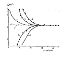
- preforms with a step index profile in the core area were produced using the PCVD process; all deposition conditions apart from the interruption period were kept constant.
- quartz glass tubes 23 x 20 mm
- the resonator speed was 11.7 cm s- 1 in the constant range over a stroke length of 70 cm and was decelerated to zero at the end points over a ramp length of 1.2 cm each and accelerated in the same direction to the setpoint in the reverse direction.
- the glass tubes were collapsed after deposition and then with a P101-Preform analysesr (Fa. Yorck echnology T) with respect to the core geometry (radius r co), and the optical refractive index difference between the deposited core material and Si0 2 substrate tube as a function of the stroke length zp.
- the measurement results are shown graphically in the drawing. With this type of measurement, the position of the deposition with reference to the resonator center (or the reversal points), the geometric mass assignment and the optical refractive index along the preform can be determined simultaneously.
- the following results and exemplary embodiments essentially show only the geometric initial taper or the effect of the method according to the invention on the reduction of the taper area.
- the agreement of the calculated values for the core radius with the experimentally measured core radii confirmed that the process yield was quantitative in all exemplary embodiments.
Landscapes
- Chemical & Material Sciences (AREA)
- Engineering & Computer Science (AREA)
- Life Sciences & Earth Sciences (AREA)
- Plasma & Fusion (AREA)
- Chemical Kinetics & Catalysis (AREA)
- General Chemical & Material Sciences (AREA)
- Physics & Mathematics (AREA)
- General Life Sciences & Earth Sciences (AREA)
- Geochemistry & Mineralogy (AREA)
- Manufacturing & Machinery (AREA)
- Materials Engineering (AREA)
- Organic Chemistry (AREA)
- Manufacture, Treatment Of Glass Fibers (AREA)
Applications Claiming Priority (2)
| Application Number | Priority Date | Filing Date | Title |
|---|---|---|---|
| DE3525979 | 1985-07-20 | ||
| DE19853525979 DE3525979A1 (de) | 1985-07-20 | 1985-07-20 | Verfahren zur herstellung von lichtleitfasern |
Publications (2)
| Publication Number | Publication Date |
|---|---|
| EP0209945A1 true EP0209945A1 (fr) | 1987-01-28 |
| EP0209945B1 EP0209945B1 (fr) | 1988-12-28 |
Family
ID=6276291
Family Applications (1)
| Application Number | Title | Priority Date | Filing Date |
|---|---|---|---|
| EP86201236A Expired EP0209945B1 (fr) | 1985-07-20 | 1986-07-15 | Procédé de fabrication de fibres optiques |
Country Status (4)
| Country | Link |
|---|---|
| EP (1) | EP0209945B1 (fr) |
| JP (1) | JPS6221729A (fr) |
| CA (1) | CA1293126C (fr) |
| DE (2) | DE3525979A1 (fr) |
Cited By (4)
| Publication number | Priority date | Publication date | Assignee | Title |
|---|---|---|---|---|
| US4857091A (en) * | 1986-10-15 | 1989-08-15 | U.S. Philips Corp. | Method of manufacturing optical fibers |
| EP0295745A3 (en) * | 1987-06-16 | 1989-11-29 | Philips Patentverwaltung Gmbh | Method for making optical fibers |
| NL1017523C2 (nl) * | 2001-03-07 | 2002-09-10 | Draka Fibre Technology Bv | Werkwijze ter vervaardiging van een optische vezel die geschikt is voor hoge transmissiesnelheden. |
| NL1023438C2 (nl) * | 2003-05-15 | 2004-11-22 | Draka Fibre Technology Bv | Werkwijze ter vervaardiging van een optische vezel, voorvorm en een optische vezel. |
Families Citing this family (2)
| Publication number | Priority date | Publication date | Assignee | Title |
|---|---|---|---|---|
| JP2892004B2 (ja) * | 1988-01-29 | 1999-05-17 | 株式会社東芝 | 単語音声認識装置 |
| US20160023939A1 (en) * | 2014-07-24 | 2016-01-28 | Ofs Fitel, Llc | Isothermal plasma cvd system for reduced taper in optical fiber preforms |
Citations (2)
| Publication number | Priority date | Publication date | Assignee | Title |
|---|---|---|---|---|
| FR2380996A1 (fr) * | 1977-02-18 | 1978-09-15 | Comp Generale Electricite | Procede de realisation d'une ebauche de fibre optique |
| GB2118165A (en) * | 1982-04-12 | 1983-10-26 | Western Electric Co | Improved manufacture of optical fibers |
Family Cites Families (1)
| Publication number | Priority date | Publication date | Assignee | Title |
|---|---|---|---|---|
| DE3445239A1 (de) * | 1984-12-12 | 1986-06-19 | Philips Patentverwaltung Gmbh, 2000 Hamburg | Verfahren zur herstellung von lichtleitfasern |
-
1985
- 1985-07-20 DE DE19853525979 patent/DE3525979A1/de not_active Withdrawn
-
1986
- 1986-07-15 DE DE8686201236T patent/DE3661529D1/de not_active Expired
- 1986-07-15 EP EP86201236A patent/EP0209945B1/fr not_active Expired
- 1986-07-17 CA CA000514013A patent/CA1293126C/fr not_active Expired - Lifetime
- 1986-07-19 JP JP61169065A patent/JPS6221729A/ja active Pending
Patent Citations (2)
| Publication number | Priority date | Publication date | Assignee | Title |
|---|---|---|---|---|
| FR2380996A1 (fr) * | 1977-02-18 | 1978-09-15 | Comp Generale Electricite | Procede de realisation d'une ebauche de fibre optique |
| GB2118165A (en) * | 1982-04-12 | 1983-10-26 | Western Electric Co | Improved manufacture of optical fibers |
Cited By (11)
| Publication number | Priority date | Publication date | Assignee | Title |
|---|---|---|---|---|
| US4857091A (en) * | 1986-10-15 | 1989-08-15 | U.S. Philips Corp. | Method of manufacturing optical fibers |
| EP0295745A3 (en) * | 1987-06-16 | 1989-11-29 | Philips Patentverwaltung Gmbh | Method for making optical fibers |
| NL1017523C2 (nl) * | 2001-03-07 | 2002-09-10 | Draka Fibre Technology Bv | Werkwijze ter vervaardiging van een optische vezel die geschikt is voor hoge transmissiesnelheden. |
| WO2002070416A1 (fr) * | 2001-03-07 | 2002-09-12 | Draka Fibre Technology B.V. | Procédé de fabrication d'une fibre optique admettant des débits de transmission élevés |
| US7068895B2 (en) | 2001-03-07 | 2006-06-27 | Draka Fibre Technology B. V. | Method of manufacturing an optical fibre suitable for high transmission rates |
| US7116877B2 (en) | 2001-03-07 | 2006-10-03 | Draka Fibre Technology B.V. | Method of manufacturing an optical fibre suitable for high transmission rates |
| KR100827727B1 (ko) * | 2001-03-07 | 2008-05-07 | 드라카 파이버 테크놀로지 비. 브이. | 고속 전송에 적합한 광섬유의 제조방법 |
| NL1023438C2 (nl) * | 2003-05-15 | 2004-11-22 | Draka Fibre Technology Bv | Werkwijze ter vervaardiging van een optische vezel, voorvorm en een optische vezel. |
| WO2004101458A1 (fr) * | 2003-05-15 | 2004-11-25 | Draka Fibre Technology B.V. | Fibre optique et preforme, et leur procede de fabrication |
| US7068899B2 (en) | 2003-05-15 | 2006-06-27 | Draka Fibre Technology B.V. | Method for the production of an optical fibre, preform, and an optical fibre |
| US7522800B2 (en) | 2003-05-15 | 2009-04-21 | Draka Comteq B.V. | Method for the production of an optical fibre, preform, and an optical fibre |
Also Published As
| Publication number | Publication date |
|---|---|
| DE3661529D1 (en) | 1989-02-02 |
| CA1293126C (fr) | 1991-12-17 |
| EP0209945B1 (fr) | 1988-12-28 |
| JPS6221729A (ja) | 1987-01-30 |
| DE3525979A1 (de) | 1987-01-29 |
Similar Documents
| Publication | Publication Date | Title |
|---|---|---|
| EP0187405B1 (fr) | Procédé pour la fabrication de fibres optiques | |
| DE2434717C2 (de) | Verfahren zur Herstellung eines Glasfaser-Lichtleiters | |
| DE3105295C2 (fr) | ||
| EP0046281B1 (fr) | Procédé pour la fabrication d'un verre à profil d'indice de réfraction prédéterminé ayant la forme d'un profil gradient d'indice et procédé d'obtention d'une préforme en verre pour l'étirage de fibres optiques pour la technique des communications | |
| EP0117009B1 (fr) | Procédé de fabrication d'une préforme pleine pour l'étirage de fibres optiques | |
| DE3731604A1 (de) | Verfahren zur herstellung einer monomode-lichtleitfaser | |
| DE2313276A1 (de) | Verfahren zur herstellung von optischem glas | |
| DE2642949A1 (de) | Verfahren zur herstellung von innenbeschichteten glasrohren zum ziehen von lichtleitfasern | |
| DE2538313A1 (de) | Verfahren zur herstellung eines vorproduktes fuer die erzeugung eines optischen lichtleiters | |
| DE2615534B2 (de) | Fuer die nachrichtenuebertragung geeignete lichtleitfaser mit gradientenprofil aus mehrkomponentenglaesern mit angepasstem ausdehnungskoeffizienten zwischen glaskern und glasmantel sowie verfahren zu ihrer herstellung | |
| EP0191202A2 (fr) | Fibres optiques dopées par le fluor et leur procédé de fabrication | |
| EP0392599A2 (fr) | Procédé pour la fabrication de corps en verre avec des domaines de réfraction optique différente | |
| EP0209945B1 (fr) | Procédé de fabrication de fibres optiques | |
| EP0295745B1 (fr) | Procédé de fabrication de fibres optiques | |
| EP0134480B1 (fr) | Procédé de fabrication de verre par dépôt à partir de la phase gazeuse | |
| DE2913726A1 (de) | Verfahren zum herstellen einer vorform fuer optische glasfasern | |
| EP0536631B1 (fr) | Procédé de fabrication d'une préforme pour fibres optiques | |
| DE10102611B4 (de) | Verfahren zur Herstellung eines SiO2-Rohlings | |
| EP0132011B1 (fr) | Procédé de fabrication de guides de lumière en fibre | |
| DE3206180A1 (de) | Verfahren zur herstellung einer vorform, aus der optische fasern ziehbar sind | |
| DE2938218C2 (de) | Verfahren zur Herstellung eines Glasgegenstandes | |
| EP0163071B1 (fr) | Procédé pour la fabrication d'une préforme pour l'étirage de fibres optiques | |
| EP0163072B1 (fr) | Procédé pour la fabrication d'une préforme pour l'étirage de fibres optiques | |
| EP3328804B1 (fr) | Procédé de dépôt défini d'une couche de verre sur une paroi intérieure d'une préforme | |
| DE3886121T2 (de) | Verfahren zur Herstellung optischer Fasern und dadurch hergestellte Produkte. |
Legal Events
| Date | Code | Title | Description |
|---|---|---|---|
| PUAI | Public reference made under article 153(3) epc to a published international application that has entered the european phase |
Free format text: ORIGINAL CODE: 0009012 |
|
| AK | Designated contracting states |
Kind code of ref document: A1 Designated state(s): CH DE FR GB IT LI NL SE |
|
| 17P | Request for examination filed |
Effective date: 19870526 |
|
| RAP1 | Party data changed (applicant data changed or rights of an application transferred) |
Owner name: N.V. PHILIPS' GLOEILAMPENFABRIEKEN Owner name: PHILIPS PATENTVERWALTUNG GMBH |
|
| 17Q | First examination report despatched |
Effective date: 19880219 |
|
| GRAA | (expected) grant |
Free format text: ORIGINAL CODE: 0009210 |
|
| AK | Designated contracting states |
Kind code of ref document: B1 Designated state(s): CH DE FR GB IT LI NL SE |
|
| PG25 | Lapsed in a contracting state [announced via postgrant information from national office to epo] |
Ref country code: IT Free format text: LAPSE BECAUSE OF FAILURE TO SUBMIT A TRANSLATION OF THE DESCRIPTION OR TO PAY THE FEE WITHIN THE PRE;WARNING: LAPSES OF ITALIAN PATENTS WITH EFFECTIVE DATE BEFORE 2007 MAY HAVE OCCURRED AT ANY TIME BEFORE 2007. THE CORRECT EFFECTIVE DATE MAY BE DIFFERENT FROM THE ONE RECORDED.SCRIBED TIME-LIMIT Effective date: 19881228 Ref country code: SE Effective date: 19881228 Ref country code: NL Effective date: 19881228 |
|
| REF | Corresponds to: |
Ref document number: 3661529 Country of ref document: DE Date of ref document: 19890202 |
|
| GBT | Gb: translation of ep patent filed (gb section 77(6)(a)/1977) | ||
| ET | Fr: translation filed | ||
| NLV1 | Nl: lapsed or annulled due to failure to fulfill the requirements of art. 29p and 29m of the patents act | ||
| PG25 | Lapsed in a contracting state [announced via postgrant information from national office to epo] |
Ref country code: LI Effective date: 19890731 Ref country code: CH Effective date: 19890731 |
|
| PLBE | No opposition filed within time limit |
Free format text: ORIGINAL CODE: 0009261 |
|
| STAA | Information on the status of an ep patent application or granted ep patent |
Free format text: STATUS: NO OPPOSITION FILED WITHIN TIME LIMIT |
|
| 26N | No opposition filed | ||
| REG | Reference to a national code |
Ref country code: CH Ref legal event code: PL |
|
| PGFP | Annual fee paid to national office [announced via postgrant information from national office to epo] |
Ref country code: GB Payment date: 19940629 Year of fee payment: 9 |
|
| PGFP | Annual fee paid to national office [announced via postgrant information from national office to epo] |
Ref country code: FR Payment date: 19940727 Year of fee payment: 9 |
|
| PGFP | Annual fee paid to national office [announced via postgrant information from national office to epo] |
Ref country code: DE Payment date: 19940927 Year of fee payment: 9 |
|
| PG25 | Lapsed in a contracting state [announced via postgrant information from national office to epo] |
Ref country code: GB Effective date: 19950715 |
|
| GBPC | Gb: european patent ceased through non-payment of renewal fee |
Effective date: 19950715 |
|
| PG25 | Lapsed in a contracting state [announced via postgrant information from national office to epo] |
Ref country code: DE Effective date: 19960402 |
|
| PG25 | Lapsed in a contracting state [announced via postgrant information from national office to epo] |
Ref country code: FR Effective date: 19960430 |
|
| REG | Reference to a national code |
Ref country code: FR Ref legal event code: ST |
|
| REG | Reference to a national code |
Ref country code: FR Ref legal event code: ST |
|
| REG | Reference to a national code |
Ref country code: FR Ref legal event code: ST |