EP0209969A2 - Méthode et appareil d'implantation ionique ayant une précision de la dose ionique - Google Patents
Méthode et appareil d'implantation ionique ayant une précision de la dose ionique Download PDFInfo
- Publication number
- EP0209969A2 EP0209969A2 EP86303919A EP86303919A EP0209969A2 EP 0209969 A2 EP0209969 A2 EP 0209969A2 EP 86303919 A EP86303919 A EP 86303919A EP 86303919 A EP86303919 A EP 86303919A EP 0209969 A2 EP0209969 A2 EP 0209969A2
- Authority
- EP
- European Patent Office
- Prior art keywords
- pressure
- chamber
- workpiece
- ion
- ion implantation
- Prior art date
- Legal status (The legal status is an assumption and is not a legal conclusion. Google has not performed a legal analysis and makes no representation as to the accuracy of the status listed.)
- Granted
Links
- 238000000034 method Methods 0.000 title claims description 12
- 238000005468 ion implantation Methods 0.000 claims abstract description 29
- 150000002500 ions Chemical class 0.000 claims description 29
- 239000007943 implant Substances 0.000 claims description 14
- 238000002513 implantation Methods 0.000 claims description 13
- 238000012545 processing Methods 0.000 claims description 5
- 230000001186 cumulative effect Effects 0.000 claims description 3
- 230000003472 neutralizing effect Effects 0.000 abstract description 3
- 235000012431 wafers Nutrition 0.000 description 46
- 238000010884 ion-beam technique Methods 0.000 description 15
- 238000005259 measurement Methods 0.000 description 11
- 238000005086 pumping Methods 0.000 description 10
- 238000002955 isolation Methods 0.000 description 9
- 238000010943 off-gassing Methods 0.000 description 7
- 239000004065 semiconductor Substances 0.000 description 5
- 239000012535 impurity Substances 0.000 description 4
- 238000012937 correction Methods 0.000 description 3
- 239000002019 doping agent Substances 0.000 description 3
- 238000004519 manufacturing process Methods 0.000 description 3
- 229920002120 photoresistant polymer Polymers 0.000 description 3
- 230000007935 neutral effect Effects 0.000 description 2
- 239000002245 particle Substances 0.000 description 2
- 230000001133 acceleration Effects 0.000 description 1
- 230000003679 aging effect Effects 0.000 description 1
- 238000010420 art technique Methods 0.000 description 1
- 238000011109 contamination Methods 0.000 description 1
- 238000010586 diagram Methods 0.000 description 1
- 239000006185 dispersion Substances 0.000 description 1
- 230000000694 effects Effects 0.000 description 1
- 230000007774 longterm Effects 0.000 description 1
- 230000000873 masking effect Effects 0.000 description 1
- 239000000463 material Substances 0.000 description 1
- 238000012986 modification Methods 0.000 description 1
- 230000004048 modification Effects 0.000 description 1
- 230000003287 optical effect Effects 0.000 description 1
- 230000035945 sensitivity Effects 0.000 description 1
- 238000010561 standard procedure Methods 0.000 description 1
- XLYOFNOQVPJJNP-UHFFFAOYSA-N water Chemical compound O XLYOFNOQVPJJNP-UHFFFAOYSA-N 0.000 description 1
Images

Classifications
-
- H—ELECTRICITY
- H01—ELECTRIC ELEMENTS
- H01J—ELECTRIC DISCHARGE TUBES OR DISCHARGE LAMPS
- H01J37/00—Discharge tubes with provision for introducing objects or material to be exposed to the discharge, e.g. for the purpose of examination or processing thereof
- H01J37/30—Electron-beam or ion-beam tubes for localised treatment of objects
- H01J37/317—Electron-beam or ion-beam tubes for localised treatment of objects for changing properties of the objects or for applying thin layers thereon, e.g. for ion implantation
- H01J37/3171—Electron-beam or ion-beam tubes for localised treatment of objects for changing properties of the objects or for applying thin layers thereon, e.g. for ion implantation for ion implantation
-
- H—ELECTRICITY
- H01—ELECTRIC ELEMENTS
- H01J—ELECTRIC DISCHARGE TUBES OR DISCHARGE LAMPS
- H01J37/00—Discharge tubes with provision for introducing objects or material to be exposed to the discharge, e.g. for the purpose of examination or processing thereof
- H01J37/02—Details
- H01J37/18—Vacuum locks ; Means for obtaining or maintaining the desired pressure within the vessel
-
- Y—GENERAL TAGGING OF NEW TECHNOLOGICAL DEVELOPMENTS; GENERAL TAGGING OF CROSS-SECTIONAL TECHNOLOGIES SPANNING OVER SEVERAL SECTIONS OF THE IPC; TECHNICAL SUBJECTS COVERED BY FORMER USPC CROSS-REFERENCE ART COLLECTIONS [XRACs] AND DIGESTS
- Y10—TECHNICAL SUBJECTS COVERED BY FORMER USPC
- Y10S—TECHNICAL SUBJECTS COVERED BY FORMER USPC CROSS-REFERENCE ART COLLECTIONS [XRACs] AND DIGESTS
- Y10S414/00—Material or article handling
- Y10S414/135—Associated with semiconductor wafer handling
- Y10S414/139—Associated with semiconductor wafer handling including wafer charging or discharging means for vacuum chamber
Definitions
- This invention relates to ion implantation and, more particularly, to methods and apparatus for improving ion implanatation dose accuracy by reducing measurement errors due to pressure variations in the implant chamber.
- Ion implantation has become a standard technique for introducing impurity dopants into semiconductor wafers.
- a beam of ions is generated in a source and is directed with varying degrees of acceleration toward a target wafer.
- the ions implanted into the semiconductor material form the various elements of an integrated circuit.
- Ion implantation systems typically include an ion source, ion optics for removing undesired ion species and for focusing the beam, means for deflecting the beam over the target area, and an end station for mounting and exchanging wafers.
- the entire region between the ion source and the semiconductor wafer is maintained at high vacuum to prevent dispersion of the ion beam by collisions with gas molecules.
- wafers are introduced into a vacuum ion implantation chamber through an isolation lock, are implanted and then are removed through the isolation lock. In some systems, the wafers remain in the isolation lock and are implanted through an open cate valve. Prior to implantation, the vacuum chamber is maintained at a prescribed baseline pressure level by a vacuum pumping system. When a wafer is introduced into the chamber through the isolation lock, a substantial increase in pressure occurs due to gas introduced with the wafer and outgassing of the wafer and lock surfaces. When the ion beam is applied to the wafer, another pressure increase occurs., due in part to the presence of the ion beam in the chamber, and in part to particles dislodged from the wafer by impact of the ion beam.
- the gas responsible for the pressure increase, or pressure burst, is removed by the vacuum pumping system, so as to reduce the pressure at a rate determined by several factors described hereinafter.
- ion implantation can be performed at a pressure which is an order of magnitude above the baseline pressure.
- implantation is begun shortly after the wafers are introduced into the chamber, and, as implantation proceeds, the chamber pressure is gradually reduced.
- Ion implanters customarily utilize a Faraday charge collection system to measure the ion dosage.
- the wafer is positioned in a Faraday cage which detects the charged particles in the ion beam. The measurement is integrated over time to obtain a measurement of total ion dosage applied to the wafer.
- the Faraday system accuracy is sensitive to pressure.
- the residual gas in the vacuum chamber produces errors in the measured dose due to collisions between ions in the beam and residual gas molecules outside the Faraday system. When these collisions occur, some of the ions in the beam are neutralized. Since the Faraday system registers dopant atoms only if they carry an electrical charge, the Faraday system is not able to measure the neutralized portion of the ion beam, and a dose error is introduced. The magnitude of the error depends on the number of neutralizing collisions and, hence, upon the chamber pressure.
- ion implantation apparatus comprising a processing chamber, means for evacuating the chamber to a baseline pressure, means for introducing a workpiece into the chamber, thereby causing an undesired increase in chamber pressure, means for directing a beam of positively charged ions at the workpiece, and means for controlling the pressure in the chamber after introduction of the workpiece within a specified intermediate pressure range higher than the baseline pressure, thereby reducing pressure variations during implantation.
- a method for ion implantation comprising the steps of evacuating a processing chamber to a baseline pressure, introducing a workpiece into the chamber thereby causing an increase in pressure, directing a beam of positively charged ions at the workpiece, and controlling the pressure in the chamber after introduction of the workpiece within a predetermined intermediate pressure range higher than the baseline pressure thereby reducing pressure variations during implantation.
- An end station for a serial ion implantation system in accordance with the present invention is shown in simplified form in Fig. 1.
- An ion beam 10 is generated in an ion source, is accelerated to the desired energy, typically 10 to 200 KeV, is momentum analyzed to remove undesired ion species, and is focused in the plane of the target wafer.
- the ion source and ion optical elements are shown schematically at 8.
- the ion beam is electrostatically scanned over the area of the wafer to provide uniform dosage per unit area.
- Other systems utilize mechanical scanning of the wafer or a combination of mechanical scanning and beam deflection to distribute the ion dosage. The scanning technique is not relevant to the present invention.
- a vacuum chamber 12 which is evacuated by a vacuum pumping system.
- the end station is evacuated by a vacuum pump 14.
- Semiconductor wafers are introduced into the vacuum chamber 12 through an isolation lock 16, are processed by the ion beam 10 and are removed from the chamber through the isolation lock 16.
- a semiconductor wafer 20 is lifted from a cassette wafer holder (not shown) by a wafer handler 22 and is clamped on a chamber door 24.
- the chamber door 24 is sealed to the isolation lock 16 by a door control 26.
- the lock 16 is then evacuated by a roughing vacuum pump 30; and a gate valve 32 between the lock 16 and the vacuum chamber 12 is opened.
- the operation of the wafer handling system is shown and described in more detail in US-A-4,449,885.
- the system is typically provided with a beam gate (not shown) for preventing the beam from reaching the target wafer except daring the implant cycle.
- a Faraday charge collection system 36 is mounted to receive the ion beam 10 through an aperture 40.
- the wafer 20 is positioned at the downstream end of the Faraday system 36 and forms part of the charge collection surface.
- the Faraday system 36 is electrically isolated from the vacuum chamber 12 and is connected to a dose measurement system 42.
- the Faraday system 36 operates by sensing the charges in the ion beam and converting the charges to a current. The current is sensed and integrated over time by the dose measurement system 42 to provide a measurement of the cumulative impurity dosage implanted in the wafer 20. Typically, when a prescribed dosage is reached, ion implantation of the wafer is automatically terminated.
- One of .the variables affecting the accuracy of the measured dose is the pressure in the implant chamber. Collisions between ions in the beam and residual gas molecules can produce neutral atoms which are not registered by the Faraday system, although such neutral atoms are implanted into the target wafer and affect wafer properties. Neutralizing collisions, therefore, cause errors in the measured dose, the magnitude of which increases as the pressure of the residual gas increases. For given pressure level and ion beam current, a correction factor can be added to the measured dose. However, in the typical production ion implanter, the pressure varies during implantation, thereby making it impractical to compensate for errors in real time by the use of correction factors.
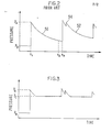
- the pressure variation during ion implantation in accordance with prior art techniques is illustrated graphically in Fig. 2.
- the baseline pressure P B is the pressure level obtained in the vacuum chamber 12 after operation of the vacuum pumping system for an extended period of time.
- the gate valve 32 is opened to expose a wafer for implantation and the pressure rapidly rises to a level P A due to the introduction of gas from the isolation lock 16.
- the pressure is reduced by operation of the vacuum pump 14, as shown by the curve 50 in Fig. 2, until an equilibrium pressure is reached.
- the wafer is implanted, and dose is monitored by the dose measurement system 42.
- a controllable vacuum valve 60 is connected in the conduit between the vacuum chamber 12 and the vacuum pump 14.
- the vacuum valve 60 includes means for controlling the flow of gas between the chamber 12 and the vacuum pump 14.
- the valve 60 includes vanes 62 which can be turned to block flow of gas into the vacuum pump 14 or turned to permit free flow of gas.
- the position of the vanes 62 is controlled by a valve motor 64.
- An example of a vacuum valve 60 is a type 253 Exhaust Valve available from MKS Instruments, Inc.
- a pressure sensor 66 such as an ion gauge is connected to measure the pressure in the chamber 12.
- a signal representing the measured pressure is supplied to a valve controller 70, the output of which is coupled to the valve motor 64.
- the valve controller 70 also receives an enable input from the dose measurement system 42, which enables its operation after a wafer is introduced into the chamber.
- the controller 70 is inhibited after completion of the implant.
- a pressure set level input establishes the level P C at which the pressure is controlled.
- the intermediate pressure level P C can be controlled at a fixed level with a linear control system or can be controlled to Furthermore, the pressure in the chamber does not always follow the curve 50 during ion implantation.
- the pressure-time curve depends both on the quantity of gas in the chamber and the rate of vacuum pumping. The rate of pumping is more or less fixed, except for long term aging effects.
- the quantity of gas depends on beam current, chamber leakage, wafer outgassing, chamber outgassing and gas introduced from the isolation lock, all of which are variable to some extent.
- This variability is illustrated in Fig. 2 by the curve 52 which represents the pressure during implantation of a second wafer.
- the initial pressure after opening of the gate valve is higher than for the previous wafer since more gas was introduced.
- a pressure burst 54 occurs when the beam is applied to the wafer, due to the presence of a photoresist masking layer on the wafer.
- the photoresist outgassing effect is well known to those skilled in the art.
- the curve 52 is, therefore, shifted upwards in relation to the curve 50, resulting in a different dose measurement error.
- the pressure in the chamber during ion implantation of a wafer is prevented from going below a predetermined intermediate pressure level Pc which is higher than the baseline pressure P B .
- the pressure P c is intermediate the baseline pressure P B , and the pressure P A , which occurs after opening of the gate valve 32.
- the chamber pressure is reduced by the vacuum pump 14 until the pressure P C is reached.
- the implant is not started until the chamber pressure reaches the level P C .
- the valve controller 70 receives a signal representative of the pressure in the chamber 12 from the pressure sensor 66.
- the pressure signal is compared with a reference level representative of the desired pressure P C .
- the valve controller 70 provides a signal to the valve motor 64 to open the valve 60, thereby allowing maximum vacuum pumping of the chamber 12.
- the valve controller 70 provides a signal to the valve motor 64 to partially close the vanes 62, thereby restricting flow of gas into the vacuum pump 14.
- the valve 60 is not completely closed since some vacuum pumping is required to remove gas leaking into the chamber and outgassing products.
- the pressure control apparatus maintains the pressure in the chamber at the level P c for the remainder of the ion implantation cycle.
- the pressure control apparatus can be inhibited when wafers are not being implanted, thereby permitting the pressure to return to the baseline level P B .
- the baseline pressure P B is on the order of 5 x 10- 7 torr
- the intermediate pressure P c is in the range of 2 x 10 -6 to 4 x 10- 6 torr. It will be understood, however, that the baseline pressure P B and the intermediate pressure P C can be established at any desired level in accordance with the present invention.
Landscapes
- Chemical & Material Sciences (AREA)
- Analytical Chemistry (AREA)
- Physical Vapour Deposition (AREA)
Applications Claiming Priority (2)
| Application Number | Priority Date | Filing Date | Title |
|---|---|---|---|
| US06/736,888 US4680474A (en) | 1985-05-22 | 1985-05-22 | Method and apparatus for improved ion dose accuracy |
| US736888 | 1991-07-29 |
Publications (3)
| Publication Number | Publication Date |
|---|---|
| EP0209969A2 true EP0209969A2 (fr) | 1987-01-28 |
| EP0209969A3 EP0209969A3 (en) | 1988-11-23 |
| EP0209969B1 EP0209969B1 (fr) | 1991-07-24 |
Family
ID=24961740
Family Applications (1)
| Application Number | Title | Priority Date | Filing Date |
|---|---|---|---|
| EP86303919A Expired - Lifetime EP0209969B1 (fr) | 1985-05-22 | 1986-05-22 | Méthode et appareil d'implantation ionique ayant une précision de la dose ionique |
Country Status (5)
| Country | Link |
|---|---|
| US (1) | US4680474A (fr) |
| EP (1) | EP0209969B1 (fr) |
| JP (1) | JP2569311B2 (fr) |
| KR (1) | KR940007875B1 (fr) |
| DE (1) | DE3680408D1 (fr) |
Families Citing this family (19)
| Publication number | Priority date | Publication date | Assignee | Title |
|---|---|---|---|---|
| US5031674A (en) * | 1989-03-03 | 1991-07-16 | Eaton Corporation | Fluid flow control method and apparatus for minimizing particle contamination |
| EP0462554B1 (fr) * | 1990-06-20 | 2000-10-11 | Hitachi, Ltd. | Appareil à faisceau de particules chargées |
| JP2973706B2 (ja) * | 1992-06-08 | 1999-11-08 | 株式会社日立製作所 | イオンビーム照射装置 |
| KR100303075B1 (ko) * | 1992-11-06 | 2001-11-30 | 조셉 제이. 스위니 | 집적회로 웨이퍼 이송 방법 및 장치 |
| KR970052183A (ko) * | 1995-12-30 | 1997-07-29 | 김주용 | 이온 빔 각도 조정이 가능한 이온 주입기 |
| US5760409A (en) * | 1996-06-14 | 1998-06-02 | Eaton Corporation | Dose control for use in an ion implanter |
| FR2756973B1 (fr) * | 1996-12-09 | 1999-01-08 | Commissariat Energie Atomique | Procede d'introduction d'une phase gazeuse dans une cavite fermee |
| US6328803B2 (en) * | 1997-02-21 | 2001-12-11 | Micron Technology, Inc. | Method and apparatus for controlling rate of pressure change in a vacuum process chamber |
| US5814819A (en) * | 1997-07-11 | 1998-09-29 | Eaton Corporation | System and method for neutralizing an ion beam using water vapor |
| US6172372B1 (en) | 1997-08-13 | 2001-01-09 | Varian Semiconductor Equipment Associates, Inc. | Scanning system with linear gas bearings and active counter-balance options |
| US6297510B1 (en) * | 1999-04-19 | 2001-10-02 | Applied Materials, Inc. | Ion implant dose control |
| US6458430B1 (en) | 1999-12-22 | 2002-10-01 | Axcelis Technologies, Inc. | Pretreatment process for plasma immersion ion implantation |
| US6568896B2 (en) | 2001-03-21 | 2003-05-27 | Applied Materials, Inc. | Transfer chamber with side wall port |
| US6583421B2 (en) | 2001-10-11 | 2003-06-24 | Diamond Semiconductor Group, Llc | Charge measuring device with wide dynamic range |
| US7009193B2 (en) * | 2003-10-31 | 2006-03-07 | Infineon Technologies Richmond, Lp | Utilization of an ion gauge in the process chamber of a semiconductor ion implanter |
| JP4219295B2 (ja) * | 2004-03-31 | 2009-02-04 | シャープ株式会社 | イオン注入装置 |
| EP1768163B1 (fr) * | 2005-09-27 | 2009-08-26 | Sharp Kabushiki Kaisha | Dispositif pour l'implantation d'ions |
| WO2007067551A2 (fr) * | 2005-12-07 | 2007-06-14 | Varian Semiconductor Equipment Associates, Inc. | Techniques permettant de reduire les effets du degazage d'une resine photosensible |
| US11562885B2 (en) * | 2020-07-28 | 2023-01-24 | Applied Materials, Inc. | Particle yield via beam-line pressure control |
Family Cites Families (5)
| Publication number | Priority date | Publication date | Assignee | Title |
|---|---|---|---|---|
| US4371774A (en) * | 1980-11-26 | 1983-02-01 | The United States Of America As Represented By The United States Department Of Energy | High power linear pulsed beam annealer |
| JPS57174467A (en) * | 1981-04-20 | 1982-10-27 | Inoue Japax Res Inc | Ion working device |
| US4449885A (en) * | 1982-05-24 | 1984-05-22 | Varian Associates, Inc. | Wafer transfer system |
| US4851691A (en) * | 1982-11-19 | 1989-07-25 | Varian Associates, Inc. | Method for photoresist pretreatment prior to charged particle beam processing |
| JPH0426456Y2 (fr) * | 1984-10-19 | 1992-06-25 |
-
1985
- 1985-05-22 US US06/736,888 patent/US4680474A/en not_active Expired - Lifetime
-
1986
- 1986-05-21 KR KR1019860003955A patent/KR940007875B1/ko not_active Expired - Fee Related
- 1986-05-21 JP JP61114996A patent/JP2569311B2/ja not_active Expired - Fee Related
- 1986-05-22 DE DE8686303919T patent/DE3680408D1/de not_active Expired - Lifetime
- 1986-05-22 EP EP86303919A patent/EP0209969B1/fr not_active Expired - Lifetime
Also Published As
| Publication number | Publication date |
|---|---|
| KR860009478A (ko) | 1986-12-23 |
| KR940007875B1 (ko) | 1994-08-26 |
| DE3680408D1 (de) | 1991-08-29 |
| EP0209969A3 (en) | 1988-11-23 |
| JPS61271739A (ja) | 1986-12-02 |
| JP2569311B2 (ja) | 1997-01-08 |
| US4680474A (en) | 1987-07-14 |
| EP0209969B1 (fr) | 1991-07-24 |
Similar Documents
| Publication | Publication Date | Title |
|---|---|---|
| US4680474A (en) | Method and apparatus for improved ion dose accuracy | |
| US4587433A (en) | Dose control apparatus | |
| KR100402183B1 (ko) | 이온주입기에서사용하는주입량제어장치및방법 | |
| US4539217A (en) | Dose control method | |
| US5998798A (en) | Ion dosage measurement apparatus for an ion beam implanter and method | |
| JP4013081B2 (ja) | イオン注入機におけるドーズ量測定制御を行うための制御機構 | |
| US6791097B2 (en) | Adjustable conductance limiting aperture for ion implanters | |
| KR100786914B1 (ko) | 이온주입 시스템을 위한 압력보상계수 결정방법 및 시스템 | |
| US6297510B1 (en) | Ion implant dose control | |
| US6984833B2 (en) | Ion implanter and method for controlling the same | |
| US11264205B2 (en) | Techniques for determining and correcting for expected dose variation during implantation of photoresist-coated substrates | |
| Jamba | Dosimetry measurement in ion implanters | |
| JPS5887746A (ja) | イオン注入装置における入射ビ−ム量測定値補正方法 | |
| JPH0426456Y2 (fr) | ||
| JP2818539B2 (ja) | イオン注入方法およびその装置 | |
| JPH01176649A (ja) | イオン打込装置の打込制御方法 | |
| JPH01225051A (ja) | イオン注入装置 | |
| JPH07176289A (ja) | イオン注入方法およびその装置 | |
| JPS62177848A (ja) | イオン打込制御方法 | |
| JPH05234561A (ja) | イオン注入装置 | |
| JPH0354850B2 (fr) |
Legal Events
| Date | Code | Title | Description |
|---|---|---|---|
| PUAI | Public reference made under article 153(3) epc to a published international application that has entered the european phase |
Free format text: ORIGINAL CODE: 0009012 |
|
| 17P | Request for examination filed |
Effective date: 19861031 |
|
| AK | Designated contracting states |
Kind code of ref document: A2 Designated state(s): DE FR GB NL |
|
| PUAL | Search report despatched |
Free format text: ORIGINAL CODE: 0009013 |
|
| AK | Designated contracting states |
Kind code of ref document: A3 Designated state(s): DE FR GB NL |
|
| 17Q | First examination report despatched |
Effective date: 19900316 |
|
| GRAA | (expected) grant |
Free format text: ORIGINAL CODE: 0009210 |
|
| AK | Designated contracting states |
Kind code of ref document: B1 Designated state(s): DE FR GB NL |
|
| ET | Fr: translation filed | ||
| REF | Corresponds to: |
Ref document number: 3680408 Country of ref document: DE Date of ref document: 19910829 |
|
| PLBE | No opposition filed within time limit |
Free format text: ORIGINAL CODE: 0009261 |
|
| STAA | Information on the status of an ep patent application or granted ep patent |
Free format text: STATUS: NO OPPOSITION FILED WITHIN TIME LIMIT |
|
| 26N | No opposition filed | ||
| PGFP | Annual fee paid to national office [announced via postgrant information from national office to epo] |
Ref country code: FR Payment date: 19960415 Year of fee payment: 11 |
|
| PGFP | Annual fee paid to national office [announced via postgrant information from national office to epo] |
Ref country code: NL Payment date: 19960417 Year of fee payment: 11 |
|
| PGFP | Annual fee paid to national office [announced via postgrant information from national office to epo] |
Ref country code: DE Payment date: 19960423 Year of fee payment: 11 |
|
| PGFP | Annual fee paid to national office [announced via postgrant information from national office to epo] |
Ref country code: GB Payment date: 19960425 Year of fee payment: 11 |
|
| PG25 | Lapsed in a contracting state [announced via postgrant information from national office to epo] |
Ref country code: GB Effective date: 19970522 |
|
| PG25 | Lapsed in a contracting state [announced via postgrant information from national office to epo] |
Ref country code: NL Effective date: 19971201 |
|
| GBPC | Gb: european patent ceased through non-payment of renewal fee |
Effective date: 19970522 |
|
| PG25 | Lapsed in a contracting state [announced via postgrant information from national office to epo] |
Ref country code: FR Free format text: LAPSE BECAUSE OF NON-PAYMENT OF DUE FEES Effective date: 19980130 |
|
| NLV4 | Nl: lapsed or anulled due to non-payment of the annual fee |
Effective date: 19971201 |
|
| PG25 | Lapsed in a contracting state [announced via postgrant information from national office to epo] |
Ref country code: DE Free format text: LAPSE BECAUSE OF NON-PAYMENT OF DUE FEES Effective date: 19980203 |
|
| REG | Reference to a national code |
Ref country code: FR Ref legal event code: ST |