EP0210287B1 - Soupape à lamelles avec bras de guidage concentriques - Google Patents
Soupape à lamelles avec bras de guidage concentriques Download PDFInfo
- Publication number
- EP0210287B1 EP0210287B1 EP85109087A EP85109087A EP0210287B1 EP 0210287 B1 EP0210287 B1 EP 0210287B1 EP 85109087 A EP85109087 A EP 85109087A EP 85109087 A EP85109087 A EP 85109087A EP 0210287 B1 EP0210287 B1 EP 0210287B1
- Authority
- EP
- European Patent Office
- Prior art keywords
- valve plate
- guides
- valve
- ring
- radially
- Prior art date
- Legal status (The legal status is an assumption and is not a legal conclusion. Google has not performed a legal analysis and makes no representation as to the accuracy of the status listed.)
- Expired
Links
Images

Classifications
-
- F—MECHANICAL ENGINEERING; LIGHTING; HEATING; WEAPONS; BLASTING
- F04—POSITIVE - DISPLACEMENT MACHINES FOR LIQUIDS; PUMPS FOR LIQUIDS OR ELASTIC FLUIDS
- F04B—POSITIVE-DISPLACEMENT MACHINES FOR LIQUIDS; PUMPS
- F04B39/00—Component parts, details, or accessories, of pumps or pumping systems specially adapted for elastic fluids, not otherwise provided for in, or of interest apart from, groups F04B25/00 - F04B37/00
- F04B39/10—Adaptations or arrangements of distribution members
- F04B39/1053—Adaptations or arrangements of distribution members the members being Hoerbigen valves
-
- F—MECHANICAL ENGINEERING; LIGHTING; HEATING; WEAPONS; BLASTING
- F16—ENGINEERING ELEMENTS AND UNITS; GENERAL MEASURES FOR PRODUCING AND MAINTAINING EFFECTIVE FUNCTIONING OF MACHINES OR INSTALLATIONS; THERMAL INSULATION IN GENERAL
- F16K—VALVES; TAPS; COCKS; ACTUATING-FLOATS; DEVICES FOR VENTING OR AERATING
- F16K15/00—Check valves
- F16K15/14—Check valves with flexible valve members
- F16K15/16—Check valves with flexible valve members with tongue-shaped laminae
Definitions
- the invention is based on a concentric plate valve known from EP-A-108 997, the valve plate of which is guided without friction and clamped between its seat and catcher plates via its arc-shaped handlebar which grows radially in the center in the web area.
- Valves of this type have the advantage that the valve plate, which is balanced between relatively long links, is guided smoothly and without tilting during operation, and seals precisely against the seat with a small clearance, with a relatively large effective opening cross-section being available, based on the installation cross-section.
- the object of the invention is to design a generic plate valve in such a way that, like a lamella valve, it essentially consists of a few simple stamped parts, but nevertheless enables an at least as large delivery rate as a known plate valve.
- the central, closed valve plate ring separates the pressure valve area and suction valve area with the sealing rings arranged above and below it, which also determine the stroke, so that both control functions required for the function of an associated piston machine can be managed with a single valve plate that is guided in a frictionless manner parallel to itself. Because the clamping bolts penetrating all valve parts are arranged in the web areas of the centrally closed valve plate ring, there is an increase in the rigidity and improvement of the sealing connection, compared to known plate valves which are braced by a central pin with lifting inserts, so that no through openings are present in the center of the valve plate could be.
- valve plate The stiffer tensioning of all valve plate parts enables the seat and catcher to be easily punched out of relatively thin material. This reduces the dead space during installation between the cylinder and cylinder head of a piston engine, which means a further increase in the delivery rate.
- a desired spring characteristic can be set in a known manner by correspondingly high pre-bending of the handlebars, individually for the suction area and the pressure area.
- Seat, catcher and the valve plate, the only movable valve element, like the sealing rings, can be punched out of thin plate material without any further processing.
- the punching tool can also achieve the permanent handlebar bend. The fitter does not have to pay attention to the correct installation of the valve plate.
- the links for the pressure and suction area run concentrically on both sides of the central closed valve plate ring, so that there can be no passage slots for the fluid.
- the steering arms should connect on both sides to the closed valve ring with the smallest possible gap of about 0.2 mm that can be achieved by laser cutting. In this case, however, it is not possible to round off the handlebar gates at the common roots to prevent long breaks.
- the gates are clamped at each common root between the sealing rings.
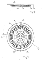
- the valve plate according to FIGS. 1 to 5 has a narrow ring 12 which runs approximately radially in the middle and in a closed manner and which, in the built-in valve (FIGS. 3 to 5), separates the suction region located within the ring from the pressure region arranged outside.
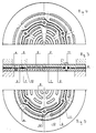
- At least one congruent sealing ring 6 or 7 is arranged above and below the closed continuous central ring 12 (FIG. 3), and the package thus formed together with the outer sealing rings 8 between seat 1 and catcher 2 is in the circumferential region of the closed ring 12 distributed screws 11 stably and tightly clamped.
- An additional bracing takes place in the installation situation shown in FIG. 3 between the cylinder (bottom) and the cylinder head (top).
- the pressure valve plate part is denoted by 4 and the suction valve plate part by 5.
- each of a common gate in the narrow central closed valve ring, the inner and outer links 10 and 9 run in opposite directions, in the same embodiment according to Figures 6 and 7 in the same direction.
Landscapes
- Engineering & Computer Science (AREA)
- General Engineering & Computer Science (AREA)
- Mechanical Engineering (AREA)
- Check Valves (AREA)
- Sliding Valves (AREA)
- Power Steering Mechanism (AREA)
Claims (2)
que lesdites lames de guidage sont découpées par groupes de deux (10, 9) à partir d'un point d'enracinement commun, de part et d'autre d'un cercle médian farmé (12) vers l'intéreur de cellui- ci jusqu'à une partie formant clapet d'aspiration (5) et vers l'extérieur jusqu'à une partie formant clapet de refoulement (4), qu'un anneau d'étanchéité au moins (6, 7) est disposé serré au-dessus et en dessous dudit cercle médian (12) et que toutes les parties énumérés ci-dessus sont traversées par des boulons de serrage (11) dans les zones de séparation.
Priority Applications (3)
| Application Number | Priority Date | Filing Date | Title |
|---|---|---|---|
| AT85109087T ATE34441T1 (de) | 1985-07-20 | 1985-07-20 | Plattenventil mit mittig ansetzenden lenkarmen. |
| DE8585109087T DE3562813D1 (en) | 1985-07-20 | 1985-07-20 | Plate valve with concentrically fastened guide arms |
| EP85109087A EP0210287B1 (fr) | 1985-07-20 | 1985-07-20 | Soupape à lamelles avec bras de guidage concentriques |
Applications Claiming Priority (1)
| Application Number | Priority Date | Filing Date | Title |
|---|---|---|---|
| EP85109087A EP0210287B1 (fr) | 1985-07-20 | 1985-07-20 | Soupape à lamelles avec bras de guidage concentriques |
Publications (2)
| Publication Number | Publication Date |
|---|---|
| EP0210287A1 EP0210287A1 (fr) | 1987-02-04 |
| EP0210287B1 true EP0210287B1 (fr) | 1988-05-18 |
Family
ID=8193632
Family Applications (1)
| Application Number | Title | Priority Date | Filing Date |
|---|---|---|---|
| EP85109087A Expired EP0210287B1 (fr) | 1985-07-20 | 1985-07-20 | Soupape à lamelles avec bras de guidage concentriques |
Country Status (3)
| Country | Link |
|---|---|
| EP (1) | EP0210287B1 (fr) |
| AT (1) | ATE34441T1 (fr) |
| DE (1) | DE3562813D1 (fr) |
Families Citing this family (5)
| Publication number | Priority date | Publication date | Assignee | Title |
|---|---|---|---|---|
| CH674756A5 (fr) * | 1988-01-19 | 1990-07-13 | Burckhardt Ag Maschf | |
| CH674755A5 (fr) * | 1988-01-19 | 1990-07-13 | Burckhardt Ag Maschf | |
| CH674757A5 (fr) * | 1988-01-19 | 1990-07-13 | Burckhardt Ag Maschf | |
| US4951706A (en) * | 1989-05-26 | 1990-08-28 | Fulton Thermatec Corporation | Flapper check valve |
| AT401549B (de) * | 1992-12-23 | 1996-09-25 | Hoerbiger Ventilwerke Ag | Selbsttätiges ventil |
Family Cites Families (1)
| Publication number | Priority date | Publication date | Assignee | Title |
|---|---|---|---|---|
| DE3307118C2 (de) * | 1982-11-06 | 1985-03-21 | Dienes Werke für Maschinenteile GmbH & Co KG, 5063 Overath | Plattenventil mit außermittig ansetzenden Ventilplattenlenkern |
-
1985
- 1985-07-20 DE DE8585109087T patent/DE3562813D1/de not_active Expired
- 1985-07-20 EP EP85109087A patent/EP0210287B1/fr not_active Expired
- 1985-07-20 AT AT85109087T patent/ATE34441T1/de not_active IP Right Cessation
Also Published As
| Publication number | Publication date |
|---|---|
| EP0210287A1 (fr) | 1987-02-04 |
| ATE34441T1 (de) | 1988-06-15 |
| DE3562813D1 (en) | 1988-06-23 |
Similar Documents
| Publication | Publication Date | Title |
|---|---|---|
| DE69119733T2 (de) | Vorrichtungen zum Montieren eines nicht umlaufenden Spirale in einer Maschine des Spiraltyps | |
| EP3556620B1 (fr) | Soupape de commande d'une installation à air comprimé | |
| EP0197320B1 (fr) | Pompe à pistons radiaux | |
| DE60205235T2 (de) | Druckbetätigtes membranabsperrventil | |
| DE68925264T2 (de) | Elektromagnetisches Drei-Wege-Ventil | |
| DE3334919A1 (de) | Fluegelradpumpe mit variabler foerderleistung | |
| DE10005180C1 (de) | Dämpfventil, insbesondere für einen Schwingungsdämpfer | |
| EP0380754B1 (fr) | Soupape de levage à force équilibrée | |
| EP1019637B1 (fr) | Moteur oscillant radial | |
| EP0210287B1 (fr) | Soupape à lamelles avec bras de guidage concentriques | |
| DE1959959A1 (de) | Ventil | |
| DE69114603T2 (de) | Regulierventil. | |
| DE2735971A1 (de) | Regelventil | |
| DE3119101C2 (fr) | ||
| EP2126428A1 (fr) | Soupape pour un système d'alimentation basse pression | |
| EP1360419B1 (fr) | Distributeur pour la commande independante de la charge d'un consommateur hydraulique en ce qui concerne la direction et la vitesse | |
| EP1628019A2 (fr) | Vérin rotatif avec une soupape de limitation de pression | |
| EP0108997B1 (fr) | Soupape à plateau avec bras d'articulation situés hors du centre | |
| EP3762638A1 (fr) | Soupape à plaque et son procédé de fonctionnement | |
| DE102008031450A1 (de) | Pumpe | |
| EP0637708B1 (fr) | Distributeur à plusieurs voies particulièrement pour commande des moteurs pneumatiques | |
| DE4028234A1 (de) | Pneumatisches ventil | |
| DE19812752C1 (de) | Schwenkmotor | |
| DE3813774C2 (fr) | ||
| DE202005021795U1 (de) | Plattenförmiges Blechbauteil |
Legal Events
| Date | Code | Title | Description |
|---|---|---|---|
| PUAI | Public reference made under article 153(3) epc to a published international application that has entered the european phase |
Free format text: ORIGINAL CODE: 0009012 |
|
| 17P | Request for examination filed |
Effective date: 19850814 |
|
| AK | Designated contracting states |
Kind code of ref document: A1 Designated state(s): AT BE CH DE FR GB IT LI LU NL SE |
|
| TCNL | Nl: translation of patent claims filed | ||
| ITCL | It: translation for ep claims filed |
Representative=s name: ING. FISCHETTI WEBER |
|
| EL | Fr: translation of claims filed | ||
| 17Q | First examination report despatched |
Effective date: 19870819 |
|
| GRAA | (expected) grant |
Free format text: ORIGINAL CODE: 0009210 |
|
| AK | Designated contracting states |
Kind code of ref document: B1 Designated state(s): AT BE CH DE FR GB IT LI LU NL SE |
|
| PG25 | Lapsed in a contracting state [announced via postgrant information from national office to epo] |
Ref country code: NL Effective date: 19880518 Ref country code: IT Free format text: LAPSE BECAUSE OF FAILURE TO SUBMIT A TRANSLATION OF THE DESCRIPTION OR TO PAY THE FEE WITHIN THE PRESCRIBED TIME-LIMIT;WARNING: LAPSES OF ITALIAN PATENTS WITH EFFECTIVE DATE BEFORE 2007 MAY HAVE OCCURRED AT ANY TIME BEFORE 2007. THE CORRECT EFFECTIVE DATE MAY BE DIFFERENT FROM THE ONE RECORDED. Effective date: 19880518 Ref country code: FR Free format text: THE PATENT HAS BEEN ANNULLED BY A DECISION OF A NATIONAL AUTHORITY Effective date: 19880518 Ref country code: BE Effective date: 19880518 |
|
| REF | Corresponds to: |
Ref document number: 34441 Country of ref document: AT Date of ref document: 19880615 Kind code of ref document: T |
|
| PG25 | Lapsed in a contracting state [announced via postgrant information from national office to epo] |
Ref country code: SE Effective date: 19880531 |
|
| GBT | Gb: translation of ep patent filed (gb section 77(6)(a)/1977) | ||
| REF | Corresponds to: |
Ref document number: 3562813 Country of ref document: DE Date of ref document: 19880623 |
|
| PG25 | Lapsed in a contracting state [announced via postgrant information from national office to epo] |
Ref country code: LU Free format text: LAPSE BECAUSE OF NON-PAYMENT OF DUE FEES Effective date: 19880731 Ref country code: LI Effective date: 19880731 Ref country code: CH Effective date: 19880731 |
|
| EN | Fr: translation not filed | ||
| NLV1 | Nl: lapsed or annulled due to failure to fulfill the requirements of art. 29p and 29m of the patents act | ||
| PLBE | No opposition filed within time limit |
Free format text: ORIGINAL CODE: 0009261 |
|
| STAA | Information on the status of an ep patent application or granted ep patent |
Free format text: STATUS: NO OPPOSITION FILED WITHIN TIME LIMIT |
|
| REG | Reference to a national code |
Ref country code: CH Ref legal event code: PL |
|
| 26N | No opposition filed | ||
| PGFP | Annual fee paid to national office [announced via postgrant information from national office to epo] |
Ref country code: DE Payment date: 19900702 Year of fee payment: 6 |
|
| PGFP | Annual fee paid to national office [announced via postgrant information from national office to epo] |
Ref country code: GB Payment date: 19900709 Year of fee payment: 6 |
|
| PGFP | Annual fee paid to national office [announced via postgrant information from national office to epo] |
Ref country code: AT Payment date: 19900711 Year of fee payment: 6 |
|
| PG25 | Lapsed in a contracting state [announced via postgrant information from national office to epo] |
Ref country code: GB Effective date: 19910720 Ref country code: AT Effective date: 19910720 |
|
| GBPC | Gb: european patent ceased through non-payment of renewal fee | ||
| PG25 | Lapsed in a contracting state [announced via postgrant information from national office to epo] |
Ref country code: DE Effective date: 19920401 |