EP0210400A1 - Träger für Magnetkopf für eine flexible Platte mit zwei Aufzeichnungsarten - Google Patents
Träger für Magnetkopf für eine flexible Platte mit zwei Aufzeichnungsarten Download PDFInfo
- Publication number
- EP0210400A1 EP0210400A1 EP19860108218 EP86108218A EP0210400A1 EP 0210400 A1 EP0210400 A1 EP 0210400A1 EP 19860108218 EP19860108218 EP 19860108218 EP 86108218 A EP86108218 A EP 86108218A EP 0210400 A1 EP0210400 A1 EP 0210400A1
- Authority
- EP
- European Patent Office
- Prior art keywords
- magnetic head
- disk
- head slider
- arm
- carriage
- Prior art date
- Legal status (The legal status is an assumption and is not a legal conclusion. Google has not performed a legal analysis and makes no representation as to the accuracy of the status listed.)
- Granted
Links
Images

Classifications
-
- G—PHYSICS
- G11—INFORMATION STORAGE
- G11B—INFORMATION STORAGE BASED ON RELATIVE MOVEMENT BETWEEN RECORD CARRIER AND TRANSDUCER
- G11B5/00—Recording by magnetisation or demagnetisation of a record carrier; Reproducing by magnetic means; Record carriers therefor
- G11B5/48—Disposition or mounting of heads or head supports relative to record carriers ; arrangements of heads, e.g. for scanning the record carrier to increase the relative speed
- G11B5/54—Disposition or mounting of heads or head supports relative to record carriers ; arrangements of heads, e.g. for scanning the record carrier to increase the relative speed with provision for moving the head into or out of its operative position or across tracks
Definitions
- the present invention relates to a magnetic head supporting mechanism for a double surface type flexible disk.
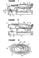
- Figure 5 is s schematic cross-sectional view showing a conventional magnetic head supporting mechanism for a double surface type flexible disk as disclosed in, for example, Japanese Unexamined Patent Publication No. 15866/1983.
- a carriage 13 is arranged so as to be movable in and along a guide lot (not shown) in the radial direction of a flexible disk 12.
- the carriage has a first magnetic head slider 14 bonded to its one end.
- the carriage also has an arm 4 coupled to the other end so as to be pivotable on a leaf spring 5.
- the arm 4 has a second magnetic head slider 15 mounted thereon by means of a gimbal spring 16.
- the arm 4 is coupled to the carriage 13 through the leaf spring which is inserted at its one end into the arm by a molding technique and which is fixed at its other end on the carriage 13 by means of a subframe 8, a screw 9 and a pressing plate.
- the arm 4 that is pivotable on the leaf spring 5 is urged in the direction toward the first magnetic head slider 14 by a torsional spring 11 extending from an end of the subframe 8.
- the second magnetic head slider 15 is mounted on the portion of the free end of the arm 4 opposing the first magnetic head slider 14.
- the second magnetic head slider 15 is moved away from the first magnetic head slider 14 as shown in Figure 6 whereby the flexible disk can be inserted.
- the first magnetic head slider 14 comprises a read/write head core, erase cores and ceramic members.
- the first magnetic head slider has a portion in contact with the flexible disk 12, which comprises a flat surface and an annular rim 14a thereabout.
- the flat surface and the annular rim 14a are connected to each other through a smooth curved surface to prevent the disk 12 from being damaged.
- the second magnetic head slider 15 comprises a read/write head core, erase cores and ceramic members like the first slider 14.
- the second magnetic head slider is in a rectangular form and is shaped flat at its portion in contact with the disk 12.
- the second magnetic head slider has a groove for avoiding overfloating of the flexible disk at its central portion.
- the second magnetic head slider 15 is bonded on the thin gimbal spring 16, ends of which are in turn bonded on the arm 4.
- the gimbal spring is made of a spring material, and has such degree of freedom that it can flex easily in every direction.
- a tapered pivotal member 4a extends to the back side of the gimbal spring 16 of the second magnetic head slider 15 mounted on the arm 4.
- the pivotal member 4a is at its leading edge in contact with the central point of the back side of the second magnetic head slider 15 so that the latter can tilt in the circumferential and radial directions of the flexible disk 12 about the leading edge of the pivotal member 4a.
- the head cores of the first and second magnetic head sliders 14, 15 are respectively on an outer position and an inner position in the radial direction of the disk with respect to a sensor for both sliders, while the head core of the second magnetic head slider occupies the inner position.
- the flexible disk 12 is inserted and the solenoid operated element is de-energized.
- the arm 4 is urged toward the flexible disk 12 by the action of the torsional spring 11.
- the second magnetic head slider 15 presses the first magnetic head slider 14 through the disk 12.
- the pressing force is determined by the spring force of the torsional spring 11 because the pressing force directly acts on the central portion of the back side of the second magnetic head slider, using as a load point the pivotal member 4a provided on the arm.
- the flexible disk When the flexible disk is rotated, its surfaces deflect vertically because of the inherent wavy motion and the vibrational wave.
- the surface of the fixed first magnetic head slider 14 facing the disk 12 is positioned to penetrate the nominal running plane of the disk, the wavy motion of the disk 12 is corrected and the disk follows the surface of the first magnetic head slider 14.
- the second magnetic head slider 15 also follows the surface of the flexible disk 12 corrected by the surface of the first magnetic head slider 14 because the second magnetic head slider 15 is pressed toward the first magnetic head slider 14 through the disk 12, using the pivotal member 4a as the load point, in a state of the second magnetic head slider closely sliding on the surface of the disk.
- the second magnetic head slider is supported by the planer position keeping function of the gimbal spring 16 having a small spring constant.
- the stage from the state with the arm 4 raised as shown in Figure 6 to the state with the read/write operation done as shown in Figure 5, and the stage from the latter to the former (These stages are called “tapping stage”.) are respectively referred to as the loading stage and the unloading stage hereinbelow.
- the arm 4 is released from the solenoid operated member to be lowered by the action of the torsional spring 11, so that the first and second magnetic head sliders 14, 15 collide with each other through the disk 12.
- the arm is lifted up by the solenoid operated element, being accompanied with the lifting of the second magnetic head slider 15.
- the second magnetic head slider 15 since the head core of the second magnetic head slider 15 lies at an inner position in comparision with that of the first magnetic head slider 14 in the radial direction of the disk, the second magnetic head slider 15 has a higher recording density to the disk than the first magnetic head slider. This penalizes the second magnetic head slider 15 in terms of error rate characteristic, especially, at the side of its inner circumference.
- the second magnetic head slider 15 carries out its following motion on the basis of the first magnetic head slider 14 and the second . magnetic head slider 15 supported by the gimbal spring 16 having a small spring constant is more sensible to the wave of the disk 12 than the first magnetic head slider. As a result, the second magnetic head slider 15 is inferior to the first magnetic head slider 14 in terms of its contact with the disk 12 besides error rate characteristic.
- a magnetic head supporting mechanism for a double surface of flexible disk wherein a first and second magnetic head sliders are respectively supported by gimbal springs having degree of freedom in every direction, the spring constant of the gimbal spring for the second magnetic head slider is set at the same value as that of the gimbal spring for the first magnetic head slider and there is provided a stopper for restricting the movement of the arm supporting the second magnetic head slider.
- a carriage 1 is arranged so as to be movable in the radial direction of a flexible disk 12 in and along a guide Slot (not shown).
- a first magnetic head slider 2 is bonded on a gimbal spring 3 to be mounted to the carriage 1 by means of the gimbal spring 3.
- the carriage 1 has an arm 4 coupled thereto so as to be pivotable on a leaf spring 5.
- a second magnetic head slider 6 is bonded on a gimbal spring 7.
- the arm 4 is coupled to an end of the carriage 1 through the leaf spring 5 which is inserted at its one end into the arm by a molding technique and which is fixed at its other end on the carriage 1 by means of a subframe 8, a screw 9 and a pressing plate 10.
- the arm which is pivotable on the leaf spring 5 is urged toward the first magnetic head slider 2 by a tor sional spring 11 extending from an end of the subframe 8.
- a stopper 8a formed at the free end of the subframe 8 for restricting the movement of the arm 4 in the direction toward the first magnetic head slider 2.
- the position of the arm 4 at the read/write stage is defined by engaging the arm with the stopper.
- the second magnetic head slider 6 is mounted by means of the gimbal spring 7 so as to confront the first slider 2.
- a control tab on the arm adjacent its free end so as to be engageble with a head load solenoid operated element (not shown).
- the solenoid operated element autimatically lifts the arm as shown in Figure 2 to move the second magnetic head slider 6 away from the first magnetic head slider 2, so that the disk can be inserted in the mechanism.
- the first magnetic head slider 2 may comprise a head core 2a for reading or writing data, erase cores and ceramic members.
- the first magnetic head slider has a flat top portion which comes in touch with the disk 12 and a groove 2b in the central portion of the top portion for preventing the disk from overfloating.
- the top surface of the first magnetic head slide has its corners chamfered and smoothly curved to prevent the disk 12 from being damaged.
- the first magnetic head slider 2 is bonded on the thin gimbal spring 3 which is made of a spring material, is easily flexible in the vertical, circumferential and radial direction of the disk 12 and has a treble annular struction with good flexibility.
- the gimbal spring 3 is bonded at its ends 3a, 3b on the carriage 1.
- the second magnetic head slider 6 and the gimbal spring 7 have respectively the same shapes as the first magnetic head slider 2 and the gimbal spring 3.
- the gimbal spring 7 is bonded at its ends 7a, 7b on the arm 4.
- the first magnetic head slider 2 and the second magnetic head slider 6 act respectively as a lower magnetic head and an upper magnetic head in the double surface type flexible disk drive mechanism.
- the head core 2a of the first magnetic head slider 2 occupies an outer position in comparison with that of the second magnetic head slider 6 in the radial direction of the disk 12.
- the arm 4 is raised by the head load solenoid operated element (not shown).
- the disk 12 is inserted as shown in Figure 1, and the arm 4 is released from the de-energized head load solenoid operated element and is to pushed the arm 4 toward the disk 12 by the action of the torsional spring 11.
- the second magnetic head slider 6 presses the first magnetic head slider 2 through the disk 12.
- the spring force of the torsional spring 11 is set at a value (e.g. about 40g) much greater than the force given to the second magnetic head slider 6 by the disk 12 and the first magnetic head slider 2, so that the torsional spring 11 and the stopper 8a provided on the subframe 8 can maintain the arm 4 at a position vertically predetermined with respect to the medium surface of the disk in the read/write stage.
- the pressing force given to the disk 12 by both magnetic head sliders 2, 6, which is caused by the deflection of the gimbal spring 3, 7 for the magnetic head sliders 2, 3 is about 12g.
- the deflection quantity of each gimbal spring 3 or 7 in the direction perpendicular to the surfaces of the disk 12 is the same as each other.
- the first and second magnetic head sliders 2, 6 are pressed by each other to comes to a standstill at a balance point on the basis of the action and reaction principle.
- the surfaces of the disk move up and down due to the inherent wavy motion and the vibrational wave.
- the first and second magnetic head sliders 2, 6 follow the vertical vibration of the flexible disk 12 to maintain good contact therewith since they are respectively fixed on the gimbal springs 3, 7 having the same spring constant and are balanced each other on the basis of the action and reaction principle.
- the arm 4 is released from the head load solenoid operated element to be lowered by the action of the torsional spring 11.
- the first magnetic head slider 2 and the second magnetic head slider 6 collide with each other through the disk 12.
- the gimbal springs 3, 7 for both slider 2, 6 flexes to moderate the shock caused by the collision.
- the stopper 8a of the subframe 8 since the lowering movement of the arm 4 is restricted by the stopper 8a of the subframe 8, excessive force is not given to both sliders 2, 6 and the disk 12.
- the arm 4 is lifted up by the head load solenoid element, accompanied by the lifting of the second magnetic head slider 6.
- the collision between the first magnetic head slider and the second magnetic head slider caused by the lifting movement of the latter as reaction can be moderated like at the loading stage.
- the gimbal spring 3 for the first magnetic head slider 2 has the same shape as the gimbal spring 7 for the second magnetic head slider 6.
- Both gimbal springs 3, 7 may have different shapes and be made of spring materials having different thicknesses or different materials while maintaining the same spring constant.
- the shape of the gimbal spring is not limited to the one as shown since if it has a gimbal structure having such degree of freedom that it can flex in every direction, the same effect as the embodiment can be obtained.
- the stopper 8a provided on the subframe 8 serves to maintain the arm 4 at a predetermined lowest position at the read/write stage.
- the stopper 8a may be provided on the carriage 1 at a position that it does not interfere with the disk 12, without provision of the subframe 8.
- the first and seconder magnetic head sliders 2, 6 are supported only by gimbal springs 3, 7, respectively, the spring constant of each gimbal spring is set at the same value, and there is provided the stopper 8a for restricting the lowering movement of the arm 4.
- the mechanism according to the present invention is good at following the disk 12.
- the pressing force by the magnetic head can be minimized to prolong the life of the disk in terms of its sliding movement and remarkably reduce the possibility of giving damage to the disk at the tapping stage, which serves to improve the error rate characteristic at the read/write stage.
Landscapes
- Supporting Of Heads In Record-Carrier Devices (AREA)
Applications Claiming Priority (2)
| Application Number | Priority Date | Filing Date | Title |
|---|---|---|---|
| JP16234285A JPS6222267A (ja) | 1985-07-23 | 1985-07-23 | 両面型フレキシブルデイスクのヘツド支持装置 |
| JP162342/85 | 1985-07-23 |
Publications (2)
| Publication Number | Publication Date |
|---|---|
| EP0210400A1 true EP0210400A1 (de) | 1987-02-04 |
| EP0210400B1 EP0210400B1 (de) | 1990-05-02 |
Family
ID=15752730
Family Applications (1)
| Application Number | Title | Priority Date | Filing Date |
|---|---|---|---|
| EP19860108218 Expired EP0210400B1 (de) | 1985-07-23 | 1986-06-16 | Träger für Magnetkopf für eine flexible Platte mit zwei Aufzeichnungsarten |
Country Status (3)
| Country | Link |
|---|---|
| EP (1) | EP0210400B1 (de) |
| JP (1) | JPS6222267A (de) |
| DE (1) | DE3670917D1 (de) |
Cited By (2)
| Publication number | Priority date | Publication date | Assignee | Title |
|---|---|---|---|---|
| GB2245748A (en) * | 1990-06-29 | 1992-01-08 | Alps Electric Co Ltd | Flexible disk drive |
| EP0407398A4 (en) * | 1988-02-26 | 1993-12-15 | Syquest Technology | Removable cartridge disc drive with radial arm voice coil actuator |
Families Citing this family (2)
| Publication number | Priority date | Publication date | Assignee | Title |
|---|---|---|---|---|
| JPH01251468A (ja) * | 1988-03-31 | 1989-10-06 | Toshiba Corp | 磁気ディスク装置 |
| US5926347A (en) * | 1995-04-17 | 1999-07-20 | Fujitsu Limited | Magnetic disk drive provided with means for pressing head against disk |
Citations (5)
| Publication number | Priority date | Publication date | Assignee | Title |
|---|---|---|---|---|
| US3772666A (en) * | 1972-04-03 | 1973-11-13 | Data General Corp | Interlaced magnetic heads |
| GB2000893A (en) * | 1977-07-07 | 1979-01-17 | Basf Ag | Device for the automatic loading/unloading of at least one magnetic head in a magnetic disc drive |
| US4197566A (en) * | 1977-12-21 | 1980-04-08 | Mitsubishi Denki Kabushiki Kaisha | Floating head slider holding apparatus and its use |
| EP0049943A1 (de) * | 1980-10-09 | 1982-04-21 | Mitsubishi Denki Kabushiki Kaisha | Bewegliche Magnetkopfanordnung für einen flexiblen doppelseitigen Plattenspeicher |
| US4379316A (en) * | 1981-06-11 | 1983-04-05 | Siemens Corporation | Read/write head carriage assembly for a floppy disk drive |
Family Cites Families (1)
| Publication number | Priority date | Publication date | Assignee | Title |
|---|---|---|---|---|
| JPS5933172B2 (ja) * | 1979-12-24 | 1984-08-14 | 新日本製鐵株式会社 | 冷延鋼板の連続焼鈍処理方法 |
-
1985
- 1985-07-23 JP JP16234285A patent/JPS6222267A/ja active Pending
-
1986
- 1986-06-16 EP EP19860108218 patent/EP0210400B1/de not_active Expired
- 1986-06-16 DE DE8686108218T patent/DE3670917D1/de not_active Expired - Lifetime
Patent Citations (5)
| Publication number | Priority date | Publication date | Assignee | Title |
|---|---|---|---|---|
| US3772666A (en) * | 1972-04-03 | 1973-11-13 | Data General Corp | Interlaced magnetic heads |
| GB2000893A (en) * | 1977-07-07 | 1979-01-17 | Basf Ag | Device for the automatic loading/unloading of at least one magnetic head in a magnetic disc drive |
| US4197566A (en) * | 1977-12-21 | 1980-04-08 | Mitsubishi Denki Kabushiki Kaisha | Floating head slider holding apparatus and its use |
| EP0049943A1 (de) * | 1980-10-09 | 1982-04-21 | Mitsubishi Denki Kabushiki Kaisha | Bewegliche Magnetkopfanordnung für einen flexiblen doppelseitigen Plattenspeicher |
| US4379316A (en) * | 1981-06-11 | 1983-04-05 | Siemens Corporation | Read/write head carriage assembly for a floppy disk drive |
Cited By (2)
| Publication number | Priority date | Publication date | Assignee | Title |
|---|---|---|---|---|
| EP0407398A4 (en) * | 1988-02-26 | 1993-12-15 | Syquest Technology | Removable cartridge disc drive with radial arm voice coil actuator |
| GB2245748A (en) * | 1990-06-29 | 1992-01-08 | Alps Electric Co Ltd | Flexible disk drive |
Also Published As
| Publication number | Publication date |
|---|---|
| EP0210400B1 (de) | 1990-05-02 |
| DE3670917D1 (de) | 1990-06-07 |
| JPS6222267A (ja) | 1987-01-30 |
Similar Documents
| Publication | Publication Date | Title |
|---|---|---|
| US4151573A (en) | Magnetic recording device for double sided media | |
| US4376294A (en) | Head loading and retraction apparatus for magnetic disc storage systems | |
| EP0259952B1 (de) | Magnetkopfhalterungssystem für eine Doppelkopfplatteneinheit | |
| US4912582A (en) | Floppy disk drive system with improved record/playback heads | |
| US4302789A (en) | Disc memory head arm lift mechanism | |
| EP0056798B1 (de) | Informationsaufzeichnungsgerät mit einer in einer kassette befindlichen platte | |
| US5455727A (en) | Transducer suspension assembly with a first pair of flanges for raising the resonant frequency and a second pair of flanges for increasing stiffness | |
| EP0210400B1 (de) | Träger für Magnetkopf für eine flexible Platte mit zwei Aufzeichnungsarten | |
| EP0044151B1 (de) | Anordnung zum Aufzeichnen und/oder Lesen binärer Daten von beiden Seiten einer flexiblen Magnetplatte | |
| EP0214597A1 (de) | Gerät zur magnetischen Aufzeichnung und Wiedergabe | |
| JPH07507415A (ja) | 直列型の偏りヘッド取付用サスペンション | |
| US4709285A (en) | Head assemblies mounted for optimum contact with a flexible magnetic disk | |
| US4791501A (en) | Magnetic head support apparatus for a two-sided floppy disk drive | |
| US5237474A (en) | Head cartridge apparatus having head supporting arm partially inserted into disk case through window formed therein | |
| US5293289A (en) | Head carriage device | |
| US4669010A (en) | Floppy disk drive | |
| KR910006573B1 (ko) | 자기기록 재생장치 | |
| US4831479A (en) | Pivot support structure for magnetic head assembly | |
| JPS60113360A (ja) | 磁気デイスク装置 | |
| JPH11273268A (ja) | ディスクドライブ装置 | |
| JPS626458A (ja) | 両面形フレキシブルデイスク装置 | |
| JPS6155185B2 (de) | ||
| JP2784685B2 (ja) | デイスク記録再生装置 | |
| JPH04305863A (ja) | 両面型のフレキシブルディスク装置のヘッド支持装置 | |
| EP1132915A1 (de) | Plattenlaufwerk |
Legal Events
| Date | Code | Title | Description |
|---|---|---|---|
| PUAI | Public reference made under article 153(3) epc to a published international application that has entered the european phase |
Free format text: ORIGINAL CODE: 0009012 |
|
| AK | Designated contracting states |
Kind code of ref document: A1 Designated state(s): DE FR GB |
|
| 17P | Request for examination filed |
Effective date: 19870616 |
|
| 17Q | First examination report despatched |
Effective date: 19881201 |
|
| GRAA | (expected) grant |
Free format text: ORIGINAL CODE: 0009210 |
|
| AK | Designated contracting states |
Kind code of ref document: B1 Designated state(s): DE FR GB |
|
| REF | Corresponds to: |
Ref document number: 3670917 Country of ref document: DE Date of ref document: 19900607 |
|
| ET | Fr: translation filed | ||
| PLBE | No opposition filed within time limit |
Free format text: ORIGINAL CODE: 0009261 |
|
| STAA | Information on the status of an ep patent application or granted ep patent |
Free format text: STATUS: NO OPPOSITION FILED WITHIN TIME LIMIT |
|
| 26N | No opposition filed | ||
| REG | Reference to a national code |
Ref country code: GB Ref legal event code: 746 Effective date: 19950523 |
|
| REG | Reference to a national code |
Ref country code: FR Ref legal event code: D6 |
|
| REG | Reference to a national code |
Ref country code: GB Ref legal event code: IF02 |
|
| PGFP | Annual fee paid to national office [announced via postgrant information from national office to epo] |
Ref country code: FR Payment date: 20050608 Year of fee payment: 20 |
|
| PGFP | Annual fee paid to national office [announced via postgrant information from national office to epo] |
Ref country code: DE Payment date: 20050609 Year of fee payment: 20 |
|
| PGFP | Annual fee paid to national office [announced via postgrant information from national office to epo] |
Ref country code: GB Payment date: 20050615 Year of fee payment: 20 |
|
| PG25 | Lapsed in a contracting state [announced via postgrant information from national office to epo] |
Ref country code: GB Free format text: LAPSE BECAUSE OF EXPIRATION OF PROTECTION Effective date: 20060615 |
|
| REG | Reference to a national code |
Ref country code: GB Ref legal event code: PE20 |