EP0210404B1 - Transmission pour véhicules - Google Patents
Transmission pour véhicules Download PDFInfo
- Publication number
- EP0210404B1 EP0210404B1 EP86108244A EP86108244A EP0210404B1 EP 0210404 B1 EP0210404 B1 EP 0210404B1 EP 86108244 A EP86108244 A EP 86108244A EP 86108244 A EP86108244 A EP 86108244A EP 0210404 B1 EP0210404 B1 EP 0210404B1
- Authority
- EP
- European Patent Office
- Prior art keywords
- electronic
- unit
- gearbox
- regulating
- engine
- Prior art date
- Legal status (The legal status is an assumption and is not a legal conclusion. Google has not performed a legal analysis and makes no representation as to the accuracy of the status listed.)
- Expired
Links
Images
Classifications
-
- B—PERFORMING OPERATIONS; TRANSPORTING
- B60—VEHICLES IN GENERAL
- B60W—CONJOINT CONTROL OF VEHICLE SUB-UNITS OF DIFFERENT TYPE OR DIFFERENT FUNCTION; CONTROL SYSTEMS SPECIALLY ADAPTED FOR HYBRID VEHICLES; ROAD VEHICLE DRIVE CONTROL SYSTEMS FOR PURPOSES NOT RELATED TO THE CONTROL OF A PARTICULAR SUB-UNIT
- B60W10/00—Conjoint control of vehicle sub-units of different type or different function
- B60W10/04—Conjoint control of vehicle sub-units of different type or different function including control of propulsion units
- B60W10/06—Conjoint control of vehicle sub-units of different type or different function including control of propulsion units including control of combustion engines
-
- B—PERFORMING OPERATIONS; TRANSPORTING
- B60—VEHICLES IN GENERAL
- B60K—ARRANGEMENT OR MOUNTING OF PROPULSION UNITS OR OF TRANSMISSIONS IN VEHICLES; ARRANGEMENT OR MOUNTING OF PLURAL DIVERSE PRIME-MOVERS IN VEHICLES; AUXILIARY DRIVES FOR VEHICLES; INSTRUMENTATION OR DASHBOARDS FOR VEHICLES; ARRANGEMENTS IN CONNECTION WITH COOLING, AIR INTAKE, GAS EXHAUST OR FUEL SUPPLY OF PROPULSION UNITS IN VEHICLES
- B60K31/00—Vehicle fittings, acting on a single sub-unit only, for automatically controlling vehicle speed, i.e. preventing speed from exceeding an arbitrarily established velocity or maintaining speed at a particular velocity, as selected by the vehicle operator
- B60K31/02—Vehicle fittings, acting on a single sub-unit only, for automatically controlling vehicle speed, i.e. preventing speed from exceeding an arbitrarily established velocity or maintaining speed at a particular velocity, as selected by the vehicle operator including electrically actuated servomechanism
-
- B—PERFORMING OPERATIONS; TRANSPORTING
- B60—VEHICLES IN GENERAL
- B60W—CONJOINT CONTROL OF VEHICLE SUB-UNITS OF DIFFERENT TYPE OR DIFFERENT FUNCTION; CONTROL SYSTEMS SPECIALLY ADAPTED FOR HYBRID VEHICLES; ROAD VEHICLE DRIVE CONTROL SYSTEMS FOR PURPOSES NOT RELATED TO THE CONTROL OF A PARTICULAR SUB-UNIT
- B60W10/00—Conjoint control of vehicle sub-units of different type or different function
- B60W10/04—Conjoint control of vehicle sub-units of different type or different function including control of propulsion units
-
- B—PERFORMING OPERATIONS; TRANSPORTING
- B60—VEHICLES IN GENERAL
- B60W—CONJOINT CONTROL OF VEHICLE SUB-UNITS OF DIFFERENT TYPE OR DIFFERENT FUNCTION; CONTROL SYSTEMS SPECIALLY ADAPTED FOR HYBRID VEHICLES; ROAD VEHICLE DRIVE CONTROL SYSTEMS FOR PURPOSES NOT RELATED TO THE CONTROL OF A PARTICULAR SUB-UNIT
- B60W10/00—Conjoint control of vehicle sub-units of different type or different function
- B60W10/10—Conjoint control of vehicle sub-units of different type or different function including control of change-speed gearings
- B60W10/101—Infinitely variable gearings
- B60W10/103—Infinitely variable gearings of fluid type
-
- B—PERFORMING OPERATIONS; TRANSPORTING
- B60—VEHICLES IN GENERAL
- B60W—CONJOINT CONTROL OF VEHICLE SUB-UNITS OF DIFFERENT TYPE OR DIFFERENT FUNCTION; CONTROL SYSTEMS SPECIALLY ADAPTED FOR HYBRID VEHICLES; ROAD VEHICLE DRIVE CONTROL SYSTEMS FOR PURPOSES NOT RELATED TO THE CONTROL OF A PARTICULAR SUB-UNIT
- B60W10/00—Conjoint control of vehicle sub-units of different type or different function
- B60W10/10—Conjoint control of vehicle sub-units of different type or different function including control of change-speed gearings
- B60W10/11—Stepped gearings
-
- B—PERFORMING OPERATIONS; TRANSPORTING
- B60—VEHICLES IN GENERAL
- B60W—CONJOINT CONTROL OF VEHICLE SUB-UNITS OF DIFFERENT TYPE OR DIFFERENT FUNCTION; CONTROL SYSTEMS SPECIALLY ADAPTED FOR HYBRID VEHICLES; ROAD VEHICLE DRIVE CONTROL SYSTEMS FOR PURPOSES NOT RELATED TO THE CONTROL OF A PARTICULAR SUB-UNIT
- B60W30/00—Purposes of road vehicle drive control systems not related to the control of a particular sub-unit, e.g. of systems using conjoint control of vehicle sub-units
- B60W30/18—Propelling the vehicle
- B60W30/188—Controlling power parameters of the driveline, e.g. determining the required power
- B60W30/1882—Controlling power parameters of the driveline, e.g. determining the required power characterised by the working point of the engine, e.g. by using engine output chart
-
- B—PERFORMING OPERATIONS; TRANSPORTING
- B60—VEHICLES IN GENERAL
- B60W—CONJOINT CONTROL OF VEHICLE SUB-UNITS OF DIFFERENT TYPE OR DIFFERENT FUNCTION; CONTROL SYSTEMS SPECIALLY ADAPTED FOR HYBRID VEHICLES; ROAD VEHICLE DRIVE CONTROL SYSTEMS FOR PURPOSES NOT RELATED TO THE CONTROL OF A PARTICULAR SUB-UNIT
- B60W2710/00—Output or target parameters relating to a particular sub-units
- B60W2710/06—Combustion engines, Gas turbines
- B60W2710/0616—Position of fuel or air injector
-
- B—PERFORMING OPERATIONS; TRANSPORTING
- B60—VEHICLES IN GENERAL
- B60W—CONJOINT CONTROL OF VEHICLE SUB-UNITS OF DIFFERENT TYPE OR DIFFERENT FUNCTION; CONTROL SYSTEMS SPECIALLY ADAPTED FOR HYBRID VEHICLES; ROAD VEHICLE DRIVE CONTROL SYSTEMS FOR PURPOSES NOT RELATED TO THE CONTROL OF A PARTICULAR SUB-UNIT
- B60W2710/00—Output or target parameters relating to a particular sub-units
- B60W2710/10—Change speed gearings
- B60W2710/1005—Transmission ratio engaged
-
- F—MECHANICAL ENGINEERING; LIGHTING; HEATING; WEAPONS; BLASTING
- F16—ENGINEERING ELEMENTS AND UNITS; GENERAL MEASURES FOR PRODUCING AND MAINTAINING EFFECTIVE FUNCTIONING OF MACHINES OR INSTALLATIONS; THERMAL INSULATION IN GENERAL
- F16H—GEARING
- F16H61/00—Control functions within control units of change-speed- or reversing-gearings for conveying rotary motion ; Control of exclusively fluid gearing, friction gearing, gearings with endless flexible members or other particular types of gearing
- F16H2061/0015—Transmission control for optimising fuel consumptions
-
- F—MECHANICAL ENGINEERING; LIGHTING; HEATING; WEAPONS; BLASTING
- F16—ENGINEERING ELEMENTS AND UNITS; GENERAL MEASURES FOR PRODUCING AND MAINTAINING EFFECTIVE FUNCTIONING OF MACHINES OR INSTALLATIONS; THERMAL INSULATION IN GENERAL
- F16H—GEARING
- F16H61/00—Control functions within control units of change-speed- or reversing-gearings for conveying rotary motion ; Control of exclusively fluid gearing, friction gearing, gearings with endless flexible members or other particular types of gearing
- F16H2061/0018—Transmission control for optimising exhaust emissions
-
- F—MECHANICAL ENGINEERING; LIGHTING; HEATING; WEAPONS; BLASTING
- F16—ENGINEERING ELEMENTS AND UNITS; GENERAL MEASURES FOR PRODUCING AND MAINTAINING EFFECTIVE FUNCTIONING OF MACHINES OR INSTALLATIONS; THERMAL INSULATION IN GENERAL
- F16H—GEARING
- F16H2306/00—Shifting
- F16H2306/40—Shifting activities
- F16H2306/48—Synchronising of new gear
Definitions
- the invention relates to a regulating and control system for a motor vehicle drive train with features according to the preamble of claim 1.
- the invention is based on a regulating and control system known from DE-A-2 811 574.
- the internal combustion engine is assigned its own motor electronics to regulate its output, and the gearbox is adapted to have its own gearbox electronics for its adapted switching.
- the positions of the accelerator pedal and gear selector which transmit the driver's wish to the electronics are not passed on directly to the internal combustion engine or the transmission, but are first fed to the electronics, processed there and only then passed on as corresponding setpoint signals.
- the electronics mentioned it is possible to vary the (proportional in conventional systems) influence of the operating elements on the actuators, for example the accelerator pedal on the throttle valve of the carburetor or the control rod of an injection pump, outside the proportionality.
- additional electronics are thus connected between the operating elements, such as the accelerator pedal, brake pedal, gear selector, and the unit-specific electronics, such as engine electronics, transmission electronics and the like, whereby the limits of operational optimization compared to the previously electronically controlled vehicle drive trains are noticeable can be expanded.
- the optimization of the regulation and control of the drive train can thus take place simultaneously taking into account the economy, the efficiency and the environmental impact, by the appropriate design and programming of the control units (engine electronics, transmission electronics and similar electronics) and the functionally higher-level electronics (host computer) Drivetrain can be controlled coordinated.
- the invention is based on the finding that the characteristics and / or the operation of a component of a drive train can be influenced or changed by another component, and by external influences (weight, temperature, terrain, etc.), and that by taking these factors into account Optimization of the regulation and control of a drive train is extensible. For example, it was previously not possible to control the internal combustion engine and the transmission depending on the operating state of the drive train and at the same time on the outside environment.
- the external environment is, for example, the terrain (driving uphill, driving on the motorway, loading the vehicle, etc.).
- the third electronics functionally superior to the engine electronics and transmission electronics is referred to only as the master computer.
- the master computer now offers the possibility of processing the driver's requests transmitted via the operating elements (accelerator pedal, brake pedal, gear selector and the like) in such a way that an adjustment of the corresponding drive train-side actuators does not follow the operating elements more or less directly, but in such a way that it does so
- An economical and comfortable operation of the drive train or the vehicle is given which takes wear and the environment into account.
- An uncontrolled operation of the pedals does not result in an uncontrolled driving style (if the steering is disregarded). The effect of a so-called "lead foot” does not appear.
- a speed post function can also be included, including the engine and transmission controls. So that Adherence to the target speed can also be carried out on a hill or downhill by automatically changing gears at the given time. Due to the simultaneous and coordinated control of the engine and transmission, it is also possible to take into account a changed torque ratio in the transmission when changing gears by adapting the engine torque in such a way that a tensile force compensation takes place. The coordinated control also avoids unnecessary shifts (upshifts).
- self-sufficient engine electronics and transmission electronics ensures the functionality of the vehicle in the event of a failure of the host computer, to which they are only functionally subordinate to the extent that they only receive setpoints from the host computer. If a setpoint to be calculated by the host computer fails, the control element signal is sent directly to it as a setpoint.
- the electronics and the host computer are preferably separate components; this enables a good adaptation to different drive systems by combining the individual components according to the respective application. It is therefore not necessary to change all control units (electronics) and drive train elements for each concept.
- the master computer essentially consists of at least one signal processing unit, input / output units as well as storage units and a microprocessor.
- the input signals from the operating elements are processed and fed to the input unit of the host computer.
- At least some of the processed signals are also simultaneously supplied to the electronics (electronic controller).
- the host computer receives the signals of the accelerator pedal positions, as well as actual values such as fuel supply position, transmission status, brake pressure and the like, as well as further measured values, such as engine torque, transmission drive speed, the pump settings and pressure of a hydraulic transmission and, if applicable, the load, engine temperature, exhaust gas values, etc. and changes these signals, referred to globally as measured values.
- the characteristic curves of the respective internal combustion engine as well as the transmission and the brake system are also stored in the master computer.
- a program is entered into the master computer, which is used to calculate setpoint signals for the engine electronics and transmission electronics using the measured values, the stored drive-specific values and an optimization criterion.
- centrally calculated target values can thus be matched to the entire drive train and the vehicle, so that not only the engine-specific data and the command variables specified by the driver via the accelerator pedal, but also the data from other drive train components and from the control unit for controlling the fuel supply to the internal combustion engine Outdoor environment should be considered. This data can then be used for coordinated influencing of all components of the drive train, so that a control of the drive unit that optimizes all these factors is possible between efficiency, wear and tear, environmental protection and driving comfort.
- the master computer is designed in such a way that it stores measured values from the past and processes them to determine the current operating mode of the vehicle. Due to the previous driving style, e.g. largely constant speed, which suggests a trip on a freeway, or heavily interrupted trips, which can be traced back to a trip within a city, the current operating mode can be determined with appropriate programming of the host computer and included in the determination of the target values.
- the software and thus the entire control unit group can be adjusted to different vehicle regulations, namely, cars or buses, garbage trucks or trucks, by means of only software changes.
- Sensors provided in the drive train record the current state of the elements of the drive train or the vehicle.
- the actual value signals can preferably be fed to the corresponding electronic parts, from where they are passed on to the master computer.
- This has the advantage that already existing components (engine plus engine electronics, transmission plus transmission electronics) can be integrated unchanged into the drive system according to the invention.
- the position of the control lever for the fuel injection quantity is supplied to the engine electronics as the actual injection quantity value.
- the actual value is compared with a target value specified by the host computer and the control signal is generated from it, which acts on the corresponding actuator.
- the drive system according to the invention can be expanded in that one or more additional electronics, such as, for example, electronics for regulating an energy store or the braking system, can be controlled via the master computer. In this way, these functions can also be controlled in a coordinated manner with the others.
- additional electronics such as, for example, electronics for regulating an energy store or the braking system
- the brake pedal it will be expedient for the brake pedal to interact mechanically / hydraulically with the brakes in the usual manner and at the same time to generate a signal for the master computer, which, in cooperation with the brake electronics, acts on the braking process in order to influence it favorably, for example blocking to avoid the brakes.
- a braking system can also optimize the braking process while maintaining a safe braking activity.
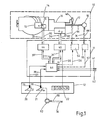
- the drive system shown in Fig. 1 consists of a drive train 10, further assigned to the components of the drive train, in the dash-dotted box 11 summarized control units and combined in box 12 controls that act on the control units.
- An internal combustion engine 14 with an associated fuel supply system 15, a transmission 16 with an associated output axle 17, and the drive wheel axle 18, a braking energy store 40 and the braking system 52 form the drive train 10.
- the driver uses, as usual, an accelerator pedal 20, a brake pedal 21 and a shift lever 22.
- the pedal travel or angle ag, a b is measured in each case by a travel sensor 26 or 27, which output the corresponding signals 28, 29 .
- the shift lever 22 indicates the respectively desired operating mode (forward, reverse travel V, R, idle N or level, rising, falling Fart 1, 2, 3) via corresponding signals 30.
- the signals 27, 29, 30 represent the driver's desire to drive.
- sensors, not shown in greater detail, assigned to the energy store 40 and the brake system 52 are provided, which deliver corresponding actual signals 33 to 36.
- Sensors 41, 42 provide further measured values or vehicle data, such as Acceleration, oil pressure, engine temperature, exhaust gas, vehicle weight, etc.
- control units drawn within the border 11 consist of motor electronics 44 for regulating the fuel supply for the internal combustion engine 14, transmission electronics 45 for regulating the transmission ratio of the transmission 16, and a master computer 46 functionally superordinate to the two electronics parts 44 and 45, which consists of the
- the aforementioned measured values 27, 29, 41, 42, 33, 34 or 33 'and 34' are used to calculate target values 50 and 51 for the motor electronics 44 or gear electronics 45.
- the accelerator pedal 20 acts exclusively on the master computer 46 in the case of FIG. 1, while the brake pedal 21 actuates the brakes 52 in the usual manner and additionally outputs the signal 29 to the master computer 46.
- the signals 30 of the gear switch 22 are input directly to the transmission electronics 45. However, it is also possible to feed this signal 30 and the brake pedal signal 29 directly to the host computer 46.
- control units can easily be expanded by additional electronics 54, 55, which also receive target signals 56, 57 from the host computer 46 and are used to control further functional units or elements of the drive train 10.
- additional electronics 54, 55 which also receive target signals 56, 57 from the host computer 46 and are used to control further functional units or elements of the drive train 10.
- the energy store 40 can be controlled with the additional electronics 54 and the braking system can be controlled with the second additional electronics 55.
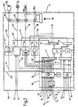
- control unit 2 shows a block diagram of the control units (electronics 44, 45, 46, 54, 55) integrated in a structural unit 11, which on the left with an interface 58 for the input signals, ie the measurement signals, and on the right with an interface 59 for the output signals that control the powertrain are limited.
- control devices electronics 44, 45, 46, 54, 55
- the motor electronics 44 and the transmission electronics 45 and any further electronics 54, 55 and the host computer 46 are to be designed and manufactured separately from one another and are only connected in the vehicle by signal supply lines.
- the master computer 46 (FIG. 2) consists of a signal processor 60 for the measured values, a microprocessor 73, a memory 74 and input-output units 71, 72, 75 and 76.
- the additional electronics 54 and 55 and the motor electronics 44, the transmission electronics 45 and associated power units 80 for controlling the actuators are integrated.
- the characteristic curves (functions of the power, the torque and the fuel consumption as a function of the engine speed) of the internal combustion engine 14, the characteristic curve for the optimal operation of the transmission 16, and the characteristic diagrams of any drive operating components are stored in the memory 74.
- the measurement data and output data of the host computer 46 are also stored over a predetermined, immediately past period.
- the driver's request regarding the driving speed is initiated by the accelerator pedal position ag and consequently the corresponding signal 27 in the signal processing 60.
- the signal 27 measured by the displacement sensor 26 is processed in the signal conditioning 60 according to a method known in control engineering and converted in an analog / digital converter 71 for a signal that can be processed in the microprocessor 73.
- the processed signal 27 ' is simultaneously fed directly to the engine electronics 44 as a setpoint specification, while the microprocessor 73 uses this signal 27', the actual value 33 and other measurement signals, namely engine speed n m , engine oil temperature t oil , gear position ap, output speed n a of the transmission 16, outside temperature, exhaust gas properties, any energy storage data, and stored data, such as the drive characteristics, a setpoint correction signal 50 'is determined.
- the setpoint correction signal 50 ' the setpoint 27' specified and processed by the accelerator pedal 20 is modified with a view to optimum operation not only of the internal combustion engine 14, but of the entire drive train 10.
- the modified, ie optimized, setpoint value 50 ′ for the adjustment angle of the fuel supply actuator 25 is measured and processed in the engine electronics 44
- the instantaneous actual value 33 ' is compared, which corresponds to the instantaneous adjustment angle of the fuel supply actuator 25.
- the comparison signal namely the control signal 90 for the fuel supply
- the actuator 25 of the fuel supply system 15 is finally actuated via an amplifier 81 of the power electronics 80.
- the actual signal 33 of the fuel supply system 15, contrary to the example according to FIG. 1, is fed directly to the host computer 46, in which the actual signal 33 is processed with the signal processing 60 provided in the host computer 46 and sent to the microprocessor 73 and the engine electronics 44 can be passed on, which ensures the emergency function in the event of failure of the host computer 46.
- the correction signal 50 ' is not generated. In such a case, there is no need to correct the predetermined target value 27 ′, which is therefore compared to the actual signal 33 ′ for generating the control signal 90 without modification in the motor electronics 44.
- the internal combustion engine 14 is therefore continued to be operated in a conventional manner.
- the internal combustion engine control can also be carried out in such a way that the setpoint correction is carried out in the master computer 46 and that the motor electronics 44 directly receive the optimized setpoint signal 50, as is provided in the example according to FIG. 1. In the event of a failure of the master computer 46, the uncorrected, predetermined target value 27, 27 'is then transmitted.
- the host computer 46 uses the current state 34 (ap) (actual value) of the hydrostats 91 (FIG. 2), for example a hydrostatic transmission 16, the accelerator pedal signal 27, the characteristic maps of the internal combustion engine 14 and the transmission 16, of the current transmission ratio , the engine speed n m , the vehicle load, any energy storage data, the preselected operating mode V, N, R, 1 ... using the gear switch 22 calculates a target value 51 which represents the optimal gear of the transmission 16 for the current operating state of the vehicle. From this setpoint 51 and the prepared actual value 34 'and taking into account the selected operating mode 30, the corresponding gear is engaged by the transmission electronics 45.
- the information is exchanged between the internal combustion engine 14 and the transmission 16 via the control computer 46, so that the other component is also taken into account when controlling one component.
- any other factors that affect the operation can be taken into account in the determination of the setpoint values to be optimized, in order to also consider aspects such as Comfort to include environmental pollution.
- the minimum configuration of the control unit 11 contains the components described so far, namely the master computer 46, the motor electronics 44 and transmission electronics 45 and the linkage of the motor and transmission data when determining the respective target values.
- additional electronics 54 can be connected, with which an energy store 40 taking into account the engine speed n m , the pedal positions ag, a b , the operating mode signal 30, the output and an auxiliary output speed n a or n e , and characteristics of the Energy storage 40 is controlled.
- the tilting device of a refuse collection truck or a truck could also be controlled with additional electronics by measuring the corresponding pressure signals P m or P of the associated hydraulic lifting systems and processing them into control signals 56 or actuating signals 94, taking into account signals 94, 95 of associated actuating elements.
- a changeover switch 97 is provided in brake electronics 55, with which the change in brake pressure can be effected either directly in proportion to brake pedal signal 29 or via a setpoint 57 determined by master computer 46.
- the target value 57 output by the master computer 46 is determined taking into account the driving speed, the gear engaged, the actual value (brake pressure) 36 'of the brake pedal action a b , and external circumstances (rain, wind).
- the control signal 98 for the brake system 52 is calculated from the setpoint 57, the actual value 36 'and the brake pedal signal 29'.
- the control electronics 44, 45, 54, 55 can be designed according to the previously known control devices.
- the master computer 46 is then equipped so that it also takes into account the functioning of the respective control electronics.
- the control computer 46 will generally be a component separate from the control electronics 44, 45, 54, 55, which is equipped with sufficient inputs and outputs in order to obtain a universal device that can be adapted to all possible control device concepts.
- Appropriate storage of data and functions and programming of the host computer 46 optimize the driving behavior of a vehicle beyond the possibility of the individual control electronics.
- the master computer 46 recognizes when a gear shift is to be carried out. By appropriate pro the master computer 46 will output a setpoint 50 or a setpoint correction 51 which causes the addition of intermediate gas during the gear shift. However, this part of the program is only intended for vehicles or the aisles that require double-declutching.
- Another example of the higher-level coordination effect by the master computer 46 is the fulfillment of the wish to keep the driving speed constant, even on the mountain or downhill. Contrary to driving on a level route, not only the fuel supply, but also the gear ratio of the transmission must be changed.
- the computer will use the power curve and the current operating state of the internal combustion engine 14 to recognize when a gear change has to be carried out and, accordingly, outputs the signal 51 at the appropriate time to carry out the gear change.
- the control computer 46 can therefore be programmed with the function of a tempo constant.
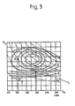
- the host computer 46 When optimizing the control of the engine 14 and the transmission 16 according to their efficiencies and the fuel consumption, the host computer 46 is at the intersection, for example with an engaged gear x and the current engine power L and engine rotation n m, from the shell diagram of the fuel consumption, see FIG. 3 A determine the consumption. Before the master computer 46 initiates a gear change x ⁇ 1, it first determines the consumption or working point B, which results from a gear change and the subsequent change in speed along the power line L. If this point is outside of a possible business or on a mussel line of higher consumption, the gear change is not carried out.
- the host computer 46 determines the current acceleration. If this is very small, the gear change is carried out.
Landscapes
- Engineering & Computer Science (AREA)
- Chemical & Material Sciences (AREA)
- Combustion & Propulsion (AREA)
- Transportation (AREA)
- Mechanical Engineering (AREA)
- Automation & Control Theory (AREA)
- Control Of Driving Devices And Active Controlling Of Vehicle (AREA)
- Control Of Vehicle Engines Or Engines For Specific Uses (AREA)
- Combined Controls Of Internal Combustion Engines (AREA)
Claims (11)
en prenant en considération le type de construction, le type d'utilisation et la charge du véhicule automobile, valeurs de consigne qui sont fournies à l'électronique du moteur et à l'électronique de transmission comme signaux pilotes d'ordres supérieurs pour la régulation correspondante des composants de la ligne d'entraînement.
Applications Claiming Priority (2)
| Application Number | Priority Date | Filing Date | Title |
|---|---|---|---|
| DE3526671 | 1985-07-25 | ||
| DE19853526671 DE3526671A1 (de) | 1985-07-25 | 1985-07-25 | Antriebsstrang fuer kraftfahrzeuge |
Publications (2)
| Publication Number | Publication Date |
|---|---|
| EP0210404A1 EP0210404A1 (fr) | 1987-02-04 |
| EP0210404B1 true EP0210404B1 (fr) | 1989-07-26 |
Family
ID=6276774
Family Applications (1)
| Application Number | Title | Priority Date | Filing Date |
|---|---|---|---|
| EP86108244A Expired EP0210404B1 (fr) | 1985-07-25 | 1986-06-16 | Transmission pour véhicules |
Country Status (4)
| Country | Link |
|---|---|
| US (1) | US4866622A (fr) |
| EP (1) | EP0210404B1 (fr) |
| JP (1) | JPS6226344A (fr) |
| DE (2) | DE3526671A1 (fr) |
Families Citing this family (37)
| Publication number | Priority date | Publication date | Assignee | Title |
|---|---|---|---|---|
| DE3624456C2 (de) * | 1986-07-19 | 1994-11-10 | Bayerische Motoren Werke Ag | Elektronisches System für ein Kraftfahrzeug |
| DE3724070A1 (de) * | 1987-07-21 | 1989-02-02 | Teves Gmbh Alfred | Verfahren und vorrichtung zum rangieren eines fahrzeuges |
| DE3866113D1 (de) * | 1987-08-17 | 1991-12-12 | Zahnradfabrik Friedrichshafen | Steuereinrictung zum selbsttaetigen schalten von stufenwechselgetrieben. |
| DE3864265D1 (de) * | 1987-10-12 | 1991-09-19 | Auto Polly Gmbh | Verfahren und vorrichtung zur steuerung eines kraftfahrzeug-antriebstranges. |
| JPH07117151B2 (ja) * | 1988-04-20 | 1995-12-18 | 日産自動車株式会社 | 自動変速機の変速制御装置 |
| DE3815625A1 (de) * | 1988-05-07 | 1989-11-16 | Koelner Verkehrs Betriebe Ag | Verfahren zur automatischen vorgabe von antriebsparametern im ein automatisches getriebe aufweisenden antriebsstrang eines linienbusses sowie einrichtung zur durchfuehrung des verfahrens |
| DE3831449A1 (de) * | 1988-09-16 | 1990-03-22 | Man Nutzfahrzeuge Ag | Elektronisches betriebssteuersystem fuer einen kraftfahrzeug-antriebsstrang |
| JP2507563B2 (ja) * | 1988-11-10 | 1996-06-12 | 日産自動車株式会社 | 交通渋滞認識装置 |
| DE3922051A1 (de) * | 1989-07-05 | 1991-01-24 | Porsche Ag | Verfahren und vorrichtung zur steuerung eines selbsttaetig schaltenden getriebes |
| JPH03135853A (ja) * | 1989-10-20 | 1991-06-10 | Hitachi Ltd | 自動車用制御装置および自動車制御方法 |
| US5105923A (en) * | 1990-09-27 | 1992-04-21 | Jatco Corporation | Engine braking control system for automotive automatic transmissions |
| DE4120566C2 (de) * | 1991-06-21 | 1995-04-13 | Porsche Ag | Steuereinrichtung für ein selbsttätig schaltendes Getriebe eines Kraftfahrzeugs |
| DE4134668A1 (de) * | 1991-10-19 | 1993-04-22 | Fichtel & Sachs Ag | Anordnung zur ermittlung der ruhestellung eines manuell bedienbaren handhabungsteils eines kraftfahrzeuges |
| DE19519703B4 (de) * | 1994-06-04 | 2006-06-08 | Volkswagen Ag | Antriebseinrichtung für ein Kraftfahrzeug und Verfahren zum Betreiben derselben |
| US5489007A (en) * | 1994-07-15 | 1996-02-06 | Caterpillar Inc. | Dynamic braking on an all wheel drive machine |
| JPH08318765A (ja) * | 1995-05-25 | 1996-12-03 | Hitachi Ltd | 情報化自動車制御装置及び方法 |
| DE19637210B4 (de) * | 1996-09-12 | 2007-05-24 | Siemens Ag | Antriebsstrangsteuerung für ein Kraftfahrzeug |
| DE19637209B4 (de) * | 1996-09-12 | 2006-12-14 | Siemens Ag | Verfahren zum Steuern des Antriebsstrangs eines Kraftfahrzeugs und integrierte Antriebsstrangsteuerung |
| DE19704841A1 (de) * | 1997-02-08 | 1998-08-13 | Itt Mfg Enterprises Inc | Verfahren und Vorrichtung zur Regelung der Längsdynamik eines Fahrzeugs |
| US6167339A (en) * | 1997-05-30 | 2000-12-26 | Continential Isad Electronic Systems Gmbh | Drive system for a vehicle and method for operating a drive system |
| DE19722808A1 (de) * | 1997-05-30 | 1998-12-03 | Isad Electronic Sys Gmbh & Co | Antriebssystem, insbesondere für ein Kraftfahrzeug, sowie Verfahren zum Betreiben eines Antriebssystems |
| DE19744218C1 (de) | 1997-10-07 | 1999-04-22 | Zahnradfabrik Friedrichshafen | Antriebsstrangsteuerung |
| EP1055547B1 (fr) * | 1999-05-19 | 2004-02-18 | Voith Turbo GmbH & Co. KG | Système de commande des éléments de propulsion d'un véhicule ferroviaire |
| DE19935353A1 (de) * | 1999-07-29 | 2001-02-01 | Abb Daimler Benz Transp | Verfahren zur Energieoptimierung bei einem Fahrzeug/Zug mit mehreren Antriebsanlagen |
| JP2002104023A (ja) * | 2000-09-29 | 2002-04-09 | Pioneer Electronic Corp | 車両用情報提供方法及び装置 |
| US20020082138A1 (en) * | 2000-12-22 | 2002-06-27 | Cannon Howard N. | Operator interface system |
| DE10127308A1 (de) * | 2001-06-06 | 2002-12-12 | Wittenstein Ag | Antriebsregelung |
| DE10138119A1 (de) * | 2001-08-03 | 2003-02-13 | Daimler Chrysler Ag | Elektronisch ansteuerbarer Antriebsstrang in einem Kraftfahrzeug sowie ein zugehöriges Betriebsverfahren |
| DE10201365A1 (de) * | 2002-01-16 | 2003-07-24 | Zahnradfabrik Friedrichshafen | Steuerungseinrichtung |
| DE10305871A1 (de) * | 2003-02-13 | 2004-08-26 | Agco Gmbh & Co. | Verfahren zum Regeln eines Fahrzeugantriebes |
| DE102005038905A1 (de) * | 2005-08-17 | 2007-02-22 | Brueninghaus Hydromatik Gmbh | Verfahren zum Regeln eines Antriebssystems und elektronische Steuereinheit |
| DE102005050544A1 (de) * | 2005-10-21 | 2007-05-03 | Zf Friedrichshafen Ag | Landwirtschaftliches Mobilfahrzeug |
| DE102006029904A1 (de) * | 2006-06-29 | 2008-01-03 | Brueninghaus Hydromatik Gmbh | Verfahren und Steuereinheit für einen Fahrantrieb |
| DE102006046399A1 (de) * | 2006-09-29 | 2008-04-03 | Robert Bosch Gmbh | Verfahren und Vorrichtung zur Fehlerverwaltung |
| JP5337359B2 (ja) | 2007-08-03 | 2013-11-06 | 株式会社小森コーポレーション | シート状物処理機の駆動制御方法および装置 |
| DE102007047724A1 (de) * | 2007-10-05 | 2009-04-09 | Robert Bosch Gmbh | Verfahren und Vorrichtung zur Ansteuerung eines Hydraulikaggregats |
| US7972239B2 (en) * | 2008-02-12 | 2011-07-05 | Caterpillar Inc. | Dual pump design for hybrid electric automatic transmission |
Citations (5)
| Publication number | Priority date | Publication date | Assignee | Title |
|---|---|---|---|---|
| EP0059426A2 (fr) * | 1981-02-24 | 1982-09-08 | Nissan Motor Co., Ltd. | Système de commande pour véhicule automobile |
| EP0073475A2 (fr) * | 1981-08-27 | 1983-03-09 | Nissan Motor Co., Ltd. | Appareil et méthode de commande d'un moteur et d'une transmission à variation continue |
| EP0108572A1 (fr) * | 1982-10-30 | 1984-05-16 | Isuzu Motors Limited | Procédé et dispositif de commande d'une transmission à commande électronique |
| EP0123083A2 (fr) * | 1983-03-11 | 1984-10-31 | Nissan Motor Co., Ltd. | Système et procédé de commande d'une automobile |
| WO1985001256A1 (fr) * | 1983-09-21 | 1985-03-28 | Robert Bosch Gmbh | Procede et circuit de determination du rapport optimal quant a la consommation d'un vehicule a moteur |
Family Cites Families (16)
| Publication number | Priority date | Publication date | Assignee | Title |
|---|---|---|---|---|
| JPS4926929A (fr) * | 1972-07-12 | 1974-03-09 | ||
| JPH0156006B2 (fr) * | 1978-03-17 | 1989-11-28 | Bosch Gmbh Robert | |
| DE2811574A1 (de) * | 1978-03-17 | 1979-09-27 | Bosch Gmbh Robert | Vorrichtung zur regelung einer antriebsmotor-getriebe-einheit eines kraftfahrzeuges |
| US4232572A (en) * | 1978-07-17 | 1980-11-11 | Sundstrand Corporation | Engine-transmission control system |
| US4262335A (en) * | 1978-08-18 | 1981-04-14 | S.R.M. Hydromekanik | Vehicle transmission control system |
| JPS55164742A (en) * | 1979-06-11 | 1980-12-22 | Hitachi Ltd | Control system for internal combustion engine |
| US4463427A (en) * | 1979-07-18 | 1984-07-31 | Renault Vehicules Industriels | Road transportation vehicle drive assist process and apparatus |
| DE2933075C2 (de) * | 1979-08-16 | 1984-04-19 | Zahnraederfabrik Renk Ag, 8900 Augsburg | Antriebs- und Bremsanlage von Kraftfahrzeugen |
| JPS56101037A (en) * | 1980-01-18 | 1981-08-13 | Nissan Motor Co Ltd | System for operating vehicle at constant speed |
| US4471437A (en) * | 1980-04-04 | 1984-09-11 | Nippon Soken, Inc. | Overdrive control apparatus |
| DE3101056A1 (de) * | 1981-01-15 | 1982-08-05 | Daimler-Benz Ag, 7000 Stuttgart | Verfahren und einrichtung zur ermittlung von schaltsignalen |
| JPS5872763A (ja) * | 1981-10-27 | 1983-04-30 | Nippon Denso Co Ltd | 車両走行制御装置 |
| US4542802A (en) * | 1982-04-02 | 1985-09-24 | Woodward Governor Company | Engine and transmission control system for combines and the like |
| US4541052A (en) * | 1982-12-20 | 1985-09-10 | General Motors Corporation | Motor vehicle power output regulation control system |
| JPS60128031A (ja) * | 1983-12-14 | 1985-07-08 | Nissan Motor Co Ltd | パワ−トレ−ンの制御方法 |
| GB8418749D0 (en) * | 1984-07-23 | 1984-08-30 | Eaton Ltd | Semi-automatic transmission control |
-
1985
- 1985-07-25 DE DE19853526671 patent/DE3526671A1/de not_active Withdrawn
-
1986
- 1986-06-16 DE DE8686108244T patent/DE3664599D1/de not_active Expired
- 1986-06-16 EP EP86108244A patent/EP0210404B1/fr not_active Expired
- 1986-06-18 US US06/875,490 patent/US4866622A/en not_active Expired - Fee Related
- 1986-07-16 JP JP61167725A patent/JPS6226344A/ja active Pending
Patent Citations (5)
| Publication number | Priority date | Publication date | Assignee | Title |
|---|---|---|---|---|
| EP0059426A2 (fr) * | 1981-02-24 | 1982-09-08 | Nissan Motor Co., Ltd. | Système de commande pour véhicule automobile |
| EP0073475A2 (fr) * | 1981-08-27 | 1983-03-09 | Nissan Motor Co., Ltd. | Appareil et méthode de commande d'un moteur et d'une transmission à variation continue |
| EP0108572A1 (fr) * | 1982-10-30 | 1984-05-16 | Isuzu Motors Limited | Procédé et dispositif de commande d'une transmission à commande électronique |
| EP0123083A2 (fr) * | 1983-03-11 | 1984-10-31 | Nissan Motor Co., Ltd. | Système et procédé de commande d'une automobile |
| WO1985001256A1 (fr) * | 1983-09-21 | 1985-03-28 | Robert Bosch Gmbh | Procede et circuit de determination du rapport optimal quant a la consommation d'un vehicule a moteur |
Non-Patent Citations (2)
| Title |
|---|
| Automotive Engineering, March 84, S.79 * |
| Bosch Technische Berichte 7 (1983) 4, S. 164, 165 * |
Also Published As
| Publication number | Publication date |
|---|---|
| EP0210404A1 (fr) | 1987-02-04 |
| JPS6226344A (ja) | 1987-02-04 |
| DE3526671A1 (de) | 1987-01-29 |
| DE3664599D1 (en) | 1989-08-31 |
| US4866622A (en) | 1989-09-12 |
Similar Documents
| Publication | Publication Date | Title |
|---|---|---|
| EP0210404A1 (fr) | Transmission pour véhicules | |
| EP0864457B1 (fr) | Système propulseur pour véhicules utilitaires | |
| EP0507072B1 (fr) | Système électronique pour une voiture | |
| EP0883510B1 (fr) | Commande de transmission pour un vehicule automobile | |
| DE19702554B4 (de) | Antriebssteuerung für ein Kraftfahrzeug | |
| DE4239711B4 (de) | Verfahren und Vorrichtung zur Steuerung eines Fahrzeugs | |
| EP0846590B1 (fr) | Procédé de réglage du moment du couple dans une système de traction Diesel-électrique et système de traction | |
| EP0739465B1 (fr) | Commande pour boite de vitesses automatique d'automobile | |
| DE3721605C2 (fr) | ||
| DE102004061321A1 (de) | Integriertes Fahrzeugsteuerungssystem | |
| DE10203954A1 (de) | Fahrzeug-Fahrsteuerungsvorrichtung | |
| DE102004062533A1 (de) | Integriertes Fahrzeugsteuerungssystem | |
| DE19810656A1 (de) | Verfahren und Vorrichtung zum statischen oder dynamischen Ermitteln von Sollwerten für Bremskräfte oder Bremsmomente | |
| EP1459928A2 (fr) | Appareil pour d'accélération et de décélération d'un vehicule et Méthode de commande de vitesse d'un vehicule | |
| DE4037237A1 (de) | Verfahren zum betreiben einer aus brennkraftmaschine und automatischem getriebe bestehenden antriebseinheit | |
| DE3831449A1 (de) | Elektronisches betriebssteuersystem fuer einen kraftfahrzeug-antriebsstrang | |
| DE19726214A1 (de) | System zur gemeinsamen Steuerung einer Servokupplung und eines Fahrzeugmotors | |
| DE19615806B4 (de) | Verfahren und Vorrichtung zur Steuerung einer Antriebseinheit eines Fahrzeuges | |
| EP1467886B1 (fr) | Procede pour la commande d'un groupe moteur hybride d'un vehicule | |
| DE112006001019T5 (de) | Antriebskraftsteuervorrichtung und -verfahren | |
| DE69516993T2 (de) | Steuerungsverfahren für ein Fahrzeugantriebsaggregat | |
| DE3841386A1 (de) | Konstant-fahrgeschwindigkeits-regelvorrichtung | |
| DE112006001003T5 (de) | Integrierte Fahrzeug-Steuervorrichtung und integriertes Fahrzeug-Steuerverfahren | |
| DE4002325A1 (de) | Schaltkennfeld eines automatikgetriebes und verfahren zum ermitteln eines schaltsignals aus dem schaltkennfeld | |
| WO2023072460A1 (fr) | Système de régulation de vitesse à commande électronique pour véhicules à moteur |
Legal Events
| Date | Code | Title | Description |
|---|---|---|---|
| PUAI | Public reference made under article 153(3) epc to a published international application that has entered the european phase |
Free format text: ORIGINAL CODE: 0009012 |
|
| AK | Designated contracting states |
Kind code of ref document: A1 Designated state(s): BE DE FR GB IT NL SE |
|
| 17P | Request for examination filed |
Effective date: 19870317 |
|
| 17Q | First examination report despatched |
Effective date: 19880114 |
|
| ITF | It: translation for a ep patent filed | ||
| GRAA | (expected) grant |
Free format text: ORIGINAL CODE: 0009210 |
|
| AK | Designated contracting states |
Kind code of ref document: B1 Designated state(s): BE DE FR GB IT NL SE |
|
| ET | Fr: translation filed | ||
| REF | Corresponds to: |
Ref document number: 3664599 Country of ref document: DE Date of ref document: 19890831 |
|
| GBT | Gb: translation of ep patent filed (gb section 77(6)(a)/1977) | ||
| RAP2 | Party data changed (patent owner data changed or rights of a patent transferred) |
Owner name: MAN TECHNOLOGIE AKTIENGESELLSCHAFT |
|
| BECN | Be: change of holder's name |
Effective date: 19890726 |
|
| NLT2 | Nl: modifications (of names), taken from the european patent patent bulletin |
Owner name: MAN TECHNOLOGIE AKTIENGESELLSCHAFT TE MUENCHEN, BO |
|
| PLBE | No opposition filed within time limit |
Free format text: ORIGINAL CODE: 0009261 |
|
| STAA | Information on the status of an ep patent application or granted ep patent |
Free format text: STATUS: NO OPPOSITION FILED WITHIN TIME LIMIT |
|
| 26N | No opposition filed | ||
| PGFP | Annual fee paid to national office [announced via postgrant information from national office to epo] |
Ref country code: GB Payment date: 19910503 Year of fee payment: 6 |
|
| PGFP | Annual fee paid to national office [announced via postgrant information from national office to epo] |
Ref country code: SE Payment date: 19910516 Year of fee payment: 6 |
|
| PGFP | Annual fee paid to national office [announced via postgrant information from national office to epo] |
Ref country code: BE Payment date: 19910531 Year of fee payment: 6 |
|
| PGFP | Annual fee paid to national office [announced via postgrant information from national office to epo] |
Ref country code: FR Payment date: 19910627 Year of fee payment: 6 |
|
| ITTA | It: last paid annual fee | ||
| PGFP | Annual fee paid to national office [announced via postgrant information from national office to epo] |
Ref country code: NL Payment date: 19910630 Year of fee payment: 6 |
|
| PGFP | Annual fee paid to national office [announced via postgrant information from national office to epo] |
Ref country code: DE Payment date: 19910711 Year of fee payment: 6 |
|
| PG25 | Lapsed in a contracting state [announced via postgrant information from national office to epo] |
Ref country code: GB Effective date: 19920616 |
|
| PG25 | Lapsed in a contracting state [announced via postgrant information from national office to epo] |
Ref country code: SE Effective date: 19920617 |
|
| PG25 | Lapsed in a contracting state [announced via postgrant information from national office to epo] |
Ref country code: BE Effective date: 19920630 |
|
| BERE | Be: lapsed |
Owner name: MAN TECHNOLOGIE A.G. Effective date: 19920630 |
|
| PG25 | Lapsed in a contracting state [announced via postgrant information from national office to epo] |
Ref country code: NL Effective date: 19930101 |
|
| GBPC | Gb: european patent ceased through non-payment of renewal fee |
Effective date: 19920616 |
|
| NLV4 | Nl: lapsed or anulled due to non-payment of the annual fee | ||
| PG25 | Lapsed in a contracting state [announced via postgrant information from national office to epo] |
Ref country code: FR Effective date: 19930226 |
|
| PG25 | Lapsed in a contracting state [announced via postgrant information from national office to epo] |
Ref country code: DE Effective date: 19930302 |
|
| REG | Reference to a national code |
Ref country code: FR Ref legal event code: ST |
|
| EUG | Se: european patent has lapsed |
Ref document number: 86108244.4 Effective date: 19930109 |
|
| PG25 | Lapsed in a contracting state [announced via postgrant information from national office to epo] |
Ref country code: IT Free format text: LAPSE BECAUSE OF NON-PAYMENT OF DUE FEES;WARNING: LAPSES OF ITALIAN PATENTS WITH EFFECTIVE DATE BEFORE 2007 MAY HAVE OCCURRED AT ANY TIME BEFORE 2007. THE CORRECT EFFECTIVE DATE MAY BE DIFFERENT FROM THE ONE RECORDED. Effective date: 20050616 |