EP0210411A2 - Méthode de fabrication d'une gaine métallique pour un câble électrique, avec un contour externe angulaire et interne arrondi - Google Patents
Méthode de fabrication d'une gaine métallique pour un câble électrique, avec un contour externe angulaire et interne arrondi Download PDFInfo
- Publication number
- EP0210411A2 EP0210411A2 EP86108322A EP86108322A EP0210411A2 EP 0210411 A2 EP0210411 A2 EP 0210411A2 EP 86108322 A EP86108322 A EP 86108322A EP 86108322 A EP86108322 A EP 86108322A EP 0210411 A2 EP0210411 A2 EP 0210411A2
- Authority
- EP
- European Patent Office
- Prior art keywords
- profile
- cable
- cusp
- radii
- flat
- Prior art date
- Legal status (The legal status is an assumption and is not a legal conclusion. Google has not performed a legal analysis and makes no representation as to the accuracy of the status listed.)
- Granted
Links
Images



Classifications
-
- H—ELECTRICITY
- H01—ELECTRIC ELEMENTS
- H01B—CABLES; CONDUCTORS; INSULATORS; SELECTION OF MATERIALS FOR THEIR CONDUCTIVE, INSULATING OR DIELECTRIC PROPERTIES
- H01B12/00—Superconductive or hyperconductive conductors, cables, or transmission lines
- H01B12/16—Superconductive or hyperconductive conductors, cables, or transmission lines characterised by cooling
-
- H—ELECTRICITY
- H01—ELECTRIC ELEMENTS
- H01B—CABLES; CONDUCTORS; INSULATORS; SELECTION OF MATERIALS FOR THEIR CONDUCTIVE, INSULATING OR DIELECTRIC PROPERTIES
- H01B13/00—Apparatus or processes specially adapted for manufacturing conductors or cables
- H01B13/22—Sheathing; Armouring; Screening; Applying other protective layers
- H01B13/26—Sheathing; Armouring; Screening; Applying other protective layers by winding, braiding or longitudinal lapping
- H01B13/2613—Sheathing; Armouring; Screening; Applying other protective layers by winding, braiding or longitudinal lapping by longitudinal lapping
- H01B13/2633—Bending and welding of a metallic screen
-
- Y—GENERAL TAGGING OF NEW TECHNOLOGICAL DEVELOPMENTS; GENERAL TAGGING OF CROSS-SECTIONAL TECHNOLOGIES SPANNING OVER SEVERAL SECTIONS OF THE IPC; TECHNICAL SUBJECTS COVERED BY FORMER USPC CROSS-REFERENCE ART COLLECTIONS [XRACs] AND DIGESTS
- Y02—TECHNOLOGIES OR APPLICATIONS FOR MITIGATION OR ADAPTATION AGAINST CLIMATE CHANGE
- Y02E—REDUCTION OF GREENHOUSE GAS [GHG] EMISSIONS, RELATED TO ENERGY GENERATION, TRANSMISSION OR DISTRIBUTION
- Y02E40/00—Technologies for an efficient electrical power generation, transmission or distribution
- Y02E40/60—Superconducting electric elements or equipment; Power systems integrating superconducting elements or equipment
Definitions
- the present invention relates to a method for producing a pressure-resistant metallic sheath for an electrical cable according to the preamble of patent claim 1.
- the disadvantage here is that the conductor sleeves produced in this way must always have the same wall thickness that has insufficient rigidity. An increase in rigidity can only be achieved by increasing the wall thickness. However, this means - in addition to the manufacturing difficulties - steel accumulations on the entire conductor sleeve and thus an increased space requirement for a winding out of the conductor. The resulting low current density is disadvantageous. Furthermore, the introduction of forces during the forming and drawing process on the actual superconductor or on the inner-conducting cable limits the application of the methods to special cable versions. Ultimately, the manufacturing processes mentioned do not allow the conductor sheath to function simultaneously with regard to a high pressure absorption inside and an optimal winding structure due to the outer shape of the conductor sheath.
- the manufacturing process should expediently be integrated in a production line.
- the sheath for the cable should be designed so that there is a simple internal structure of the cable and the internal shape for high pressures, such as. can be designed in the range of about 70 bar.
- Such requirements can e.g. can be achieved by a steel shell, which is round inside and square, rectangular or hexagonal outside.
- the present invention now proposes the method step that characterize in the the features of claim 1 are listed. Another advantageous development of such a manufacturing method is described in the characterizing part of patent claim 2.
- the cable or the cable sheath is then produced by reshaping a flat strip profile, the profile design of which is adapted in accordance with the required internal and external geometry of a pipe or a pipe half. Due to the profiling by means of the profile rollers, the sheath in the production line can be fed to the prefabricated superconducting cable or another electrical cable, applied gently and assembled into a closed tube.
- the advantage of the method according to the invention is, above all, that it enables the manufacture of tubes of variable wall thickness, which are endless in the technical sense, for example with a circular or hexagonal cross-section on the inside and outside on the outside.
- the advantages of the cable sheath formed by the method according to the invention are that corners inside the sheath are avoided. The risk of damage to the superconductor or another electrical cable, which is caused by a necessary adaptation deformation to a square outer shell contour, is thus avoided.
- the cable inside may geometry remain in the low round G eo.
- the round contour of the inside of the pipe is particularly well suited to absorbing high pressures that arise in the case of a superconducting cable, for example when transitioning into the normal line.
- the actual superconducting cable consists of the inner tube 1 as a cooling channel for liquid helium, for example, around which the conductors 2 are arranged.
- the conductors 2 are normally surrounded by insulation 3, the entire, round cable arrangement should be protected by a steel sheath 4.
- This steel shell 4 must now finally, the cable elements present in it should be able to be wound into a coil package that is as dense as possible, for example a magnet, ie the outer contour should have a square, rectangular or hexagonal cross section.
- the corners of the outer contour have radii 5 so as not to damage the insulation.
- 1 shows a square outer contour 6 with a round inner contour 7, a cable with a hexagonal outer contour basically looks the same inside.
- the outer shell 4 is composed of two halves 4a and 4b, which are symmetrically symmetrical and are joined to form a uniform shell 4 by means of the weld seams 8 between the end faces 9 and 10 of their U-shaped legs 11 and 12.
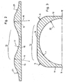
- FIG. 2 shows the cusp profile 13, which is formed into the U-profile 14 of FIG. 3 by the forming process according to FIGS. 4a-e.
- the cusp profile 13 has on its top two cusps 15 for later formation of a square or rectangular steel shell 4 or three cusps 15 for the formation of a hexagonal shell, which are rounded off with the radii 16. ⁇ ckern between or next to the top is rounded H 15, by the radii 17 and 21st
- the underside 18 of the hump profile 13 is flat, so its wall thickness is different.
- the U profile 14 of FIG. 3 later becomes a mirror image in pairs to the halves 4a and 4b of the steel shell. It has a flat base surface 19 and U-legs 11 and 12 standing perpendicularly thereon, the transitions being formed by the radii 5.
- the length of the legs 11 and 12 and the base surfaces 19 is dimensioned so that between them in front Given a given wall thickness, a semicircular cross section or half of the inner contour 7, the radius of which is 20, can be accommodated.
- the end faces of the U-legs 11 and 12 are designated 9 and 10, they are just as wide as the surface 19 is thick at the thinnest point.
- the U-profile 14 is thus angular or square on its outer contour, on its inner contour round or circular.
- FIGS. 4a-e A sequence of possible manufacturing steps for forming the hump profile 13 into the U-profile 14 is shown in FIGS. 4a-e.
- the reshaping is carried out in such a way that the bumps 15 are reshaped into the smaller radii 5 and the radius 17 in between is reshaped into a flat plane 19.
- the outer radii 21 are profiled or folded down so that the bumps 16 become the corners of a U.
- the flat underside 18 is deformed into a semicircular inner contour 7 with a finite radius 20.
- FIG. 4a Shown in FIG. 4a are preliminary stage setting or insertion rollers, in FIG. 4b a first profiling station, in FIG. 4c a second profiling station, in FIG. 4d a third profiling station and in FIG. 4e a calibration station.
- This can be followed by a further manufacturing step, followed by machining to an exact target dimension.
- the upper rollers 22 change from a hump profile as in FIG. A to a U-profile as in FIG. E, the lower rollers 23 from a flat profile as in FIG. 4a to a semicircular profile as in FIG. 4e.
- FIG. 5 A possible mechanical device for manufacturing the superconducting cable including its sheathing is shown schematically in FIG. 5.
- the prefabricated superconducting cable 24 is unwound from a reel 25 and fed straight through guide rollers 26 to the insertion rollers 27 in front of the welding station 28.
- the cupping profiles 13, which have already been prefabricated in some other way, are rolled off from two further coils or coils 29 and 30 and inserted in pairs once with the cusps upwards and once downwards into the rolling or profiling stations 31 and 32.
- Their profile rollers are designed according to FIG. 4, correspondingly mirror-symmetrically or vice versa in their profile.
- the profiling stations 31 and 32 can be reduced to a profiling station if the U-profile production is decoupled from the cable production line.
- the cusp profile is formed in a profiling station and wound up on a reel.
- the profiling stations 31, 32 can be omitted in the overall system FIG. 5 and are replaced by two reels with a deformed U-profile 14.
- U - P ro- file 14 now have their legs against each other and are brought by means of the feed-in 27 to the cable 24 so that their respective inner contour 7 closes around the cable 24 and the end surfaces 9 and 10 (see also Figures 1 and 2) come into contact with each other.
- the parting line 33 that is formed is welded in the welding station 28 by means of the weld seams 8, the superconducting cable 34 with the sheathing is finished.
- a sheath 4 produced according to the general inventive concept 1 to 3 further applications, such as e.g. Pipes for pressure-bearing media, possible.
- the manufacturing steps remain the same except for the insertion of the electrical cable.
Landscapes
- Engineering & Computer Science (AREA)
- Manufacturing & Machinery (AREA)
- Superconductors And Manufacturing Methods Therefor (AREA)
Applications Claiming Priority (2)
| Application Number | Priority Date | Filing Date | Title |
|---|---|---|---|
| DE3527714 | 1985-08-02 | ||
| DE19853527714 DE3527714A1 (de) | 1985-08-02 | 1985-08-02 | Verfahren zur herstellung einer metallischen umhuellung fuer ein elektrisches kabel mit einer aussen eckigen und innen runden kontur |
Publications (3)
| Publication Number | Publication Date |
|---|---|
| EP0210411A2 true EP0210411A2 (fr) | 1987-02-04 |
| EP0210411A3 EP0210411A3 (en) | 1988-10-12 |
| EP0210411B1 EP0210411B1 (fr) | 1991-07-17 |
Family
ID=6277475
Family Applications (1)
| Application Number | Title | Priority Date | Filing Date |
|---|---|---|---|
| EP86108322A Expired - Lifetime EP0210411B1 (fr) | 1985-08-02 | 1986-06-19 | Méthode de fabrication d'une gaine métallique pour un câble électrique, avec un contour externe angulaire et interne arrondi |
Country Status (2)
| Country | Link |
|---|---|
| EP (1) | EP0210411B1 (fr) |
| DE (1) | DE3527714A1 (fr) |
Families Citing this family (3)
| Publication number | Priority date | Publication date | Assignee | Title |
|---|---|---|---|---|
| DE102011077054A1 (de) * | 2011-06-07 | 2012-12-13 | Siemens Aktiengesellschaft | Rotor für eine elektrische Maschine und elektrische Maschine |
| DK2680381T3 (en) | 2012-06-29 | 2015-11-23 | Voestalpine Krems Gmbh | Process for producing an open or closed and especially multi-chamber hollow profile |
| DE102012218250A1 (de) | 2012-10-05 | 2014-04-10 | Bruker Eas Gmbh | Verfahren zur Fertigung eines Supraleiterdrahts, insbesondere unter Verwendung bleifreier Lote |
Family Cites Families (2)
| Publication number | Priority date | Publication date | Assignee | Title |
|---|---|---|---|---|
| GB739350A (en) * | 1953-01-23 | 1955-10-26 | Ford Motor Co | Improvements in or relating to beam members |
| GB1073958A (en) * | 1963-12-10 | 1967-06-28 | Backer Electro Vaerme A B | Improvements in or relating to a method of making sheathed insulated electric cables and an apparatus therefor |
-
1985
- 1985-08-02 DE DE19853527714 patent/DE3527714A1/de active Granted
-
1986
- 1986-06-19 EP EP86108322A patent/EP0210411B1/fr not_active Expired - Lifetime
Also Published As
| Publication number | Publication date |
|---|---|
| DE3527714A1 (de) | 1987-02-12 |
| DE3527714C2 (fr) | 1992-12-24 |
| EP0210411B1 (fr) | 1991-07-17 |
| EP0210411A3 (en) | 1988-10-12 |
Similar Documents
| Publication | Publication Date | Title |
|---|---|---|
| DE3135966C2 (de) | Verfahren zur Herstellung mehrschichtiger Schraubennahtrohre | |
| EP1480231B1 (fr) | Méthode de fabrication d'un câble supraconducteur. | |
| DE3602150A1 (de) | Elektrische mittelspannungs-kabelverbindung, insbesondere fuer oelgefuellte papierisolierte kabel | |
| DE19549406C2 (de) | Verfahren zur Herstellung eines Sektorleiters für elektrische Energiekabel | |
| EP0059971B1 (fr) | Méthode de fabrication de câbles gainés ainsi que dispositif pour l'exécution de la méthode | |
| EP0210411B1 (fr) | Méthode de fabrication d'une gaine métallique pour un câble électrique, avec un contour externe angulaire et interne arrondi | |
| DE2316123C2 (de) | Vakuumisoliertes Kryokabel | |
| DE2437279A1 (de) | Wassergekuehltes hochspannungs-energiekabel mit einem korrosionsfesten kuehlmittelrohr | |
| DE60223426T2 (de) | Herstellungsverfahren für supraleitendes Kabel | |
| DE2626384C3 (de) | Bandförmiger Supraleiter | |
| DE2049420A1 (de) | Verfahren zur kontinuierlichen Herstellung längsnahtgeschweißter Rohre | |
| DE2331757A1 (de) | Verfahren zur herstellung von druckfesten metallrohren | |
| DE3204887C2 (fr) | ||
| DE19732172B4 (de) | Verfahren zur Beseitigung von Fehlerstellen bei der Fertigung von Rohren für Kabel | |
| DE3223902C2 (de) | Verfahren zur Herstellung einer Verbindungsmuffe für Starkstromkabel und danach hergestellte Verbindungsmuffe | |
| DE618801C (de) | Verfahren zur Verlegung von an sich in der Werkstatt fertig hergestellten rohrfoermigen Leitern, insbesondere zur UEbertragung von elektrischer Energie | |
| DE3229374C2 (de) | Mehrlagige zylindrische Induktionsspule | |
| DE2001691A1 (de) | Verfahren zur Herstellung von mit laengsliegenden Draehten,Staeben oder fadenaehnlichen Koerpern durchzogenen Rohrleitungen,insbesondere von Waermelanzen | |
| EP0050092B1 (fr) | Méthode pour souder en bout des conducteurs à grande aire pour courant fort | |
| DE19508072C2 (de) | Verfahren zur Herstellung einer Isolierung für Wicklungsausleitungen mit angeschlossenen Ableitungen von Leistungstransformatoren | |
| DE2404720C3 (de) | Wassergekühltes Hochspannungs-Energiekabel | |
| EP0362609A1 (fr) | Toron conducteur à une ou plusieurs couches d'un câble d'énergie électrique, notamment d'un câble à moyenne ou haute tension, composé de brins toronnés ensemble | |
| DE2347993A1 (de) | Aus supraleitermaterial und bei der betriebstemperatur des supraleitermaterials elektrisch normalleitendem metall bestehender hohlleiter und verfahren zu dessen herstellung | |
| DE19522627A1 (de) | Verfahren zur Herstellung eines Leiters für elektrische Energiekabel | |
| EP1130437A1 (fr) | Câble optique |
Legal Events
| Date | Code | Title | Description |
|---|---|---|---|
| PUAI | Public reference made under article 153(3) epc to a published international application that has entered the european phase |
Free format text: ORIGINAL CODE: 0009012 |
|
| AK | Designated contracting states |
Kind code of ref document: A2 Designated state(s): BE CH FR GB IT LI NL |
|
| 17P | Request for examination filed |
Effective date: 19870415 |
|
| PUAL | Search report despatched |
Free format text: ORIGINAL CODE: 0009013 |
|
| AK | Designated contracting states |
Kind code of ref document: A3 Designated state(s): BE CH FR GB IT LI NL |
|
| 17Q | First examination report despatched |
Effective date: 19900924 |
|
| ITF | It: translation for a ep patent filed | ||
| GRAA | (expected) grant |
Free format text: ORIGINAL CODE: 0009210 |
|
| AK | Designated contracting states |
Kind code of ref document: B1 Designated state(s): BE CH FR GB IT LI NL |
|
| ET | Fr: translation filed | ||
| GBT | Gb: translation of ep patent filed (gb section 77(6)(a)/1977) | ||
| PLBE | No opposition filed within time limit |
Free format text: ORIGINAL CODE: 0009261 |
|
| STAA | Information on the status of an ep patent application or granted ep patent |
Free format text: STATUS: NO OPPOSITION FILED WITHIN TIME LIMIT |
|
| 26N | No opposition filed | ||
| PGFP | Annual fee paid to national office [announced via postgrant information from national office to epo] |
Ref country code: GB Payment date: 19930422 Year of fee payment: 8 |
|
| PGFP | Annual fee paid to national office [announced via postgrant information from national office to epo] |
Ref country code: CH Payment date: 19930827 Year of fee payment: 8 |
|
| PGFP | Annual fee paid to national office [announced via postgrant information from national office to epo] |
Ref country code: BE Payment date: 19930830 Year of fee payment: 8 |
|
| PGFP | Annual fee paid to national office [announced via postgrant information from national office to epo] |
Ref country code: FR Payment date: 19930831 Year of fee payment: 8 |
|
| PG25 | Lapsed in a contracting state [announced via postgrant information from national office to epo] |
Ref country code: GB Effective date: 19940619 |
|
| PG25 | Lapsed in a contracting state [announced via postgrant information from national office to epo] |
Ref country code: LI Effective date: 19940630 Ref country code: CH Effective date: 19940630 Ref country code: BE Effective date: 19940630 |
|
| PGFP | Annual fee paid to national office [announced via postgrant information from national office to epo] |
Ref country code: NL Payment date: 19940630 Year of fee payment: 9 |
|
| BERE | Be: lapsed |
Owner name: KERNFORSCHUNGSZENTRUM KARLSRUHE G.M.B.H. Effective date: 19940630 |
|
| GBPC | Gb: european patent ceased through non-payment of renewal fee |
Effective date: 19940619 |
|
| PG25 | Lapsed in a contracting state [announced via postgrant information from national office to epo] |
Ref country code: FR Effective date: 19950228 |
|
| REG | Reference to a national code |
Ref country code: CH Ref legal event code: PL |
|
| REG | Reference to a national code |
Ref country code: FR Ref legal event code: ST |
|
| PG25 | Lapsed in a contracting state [announced via postgrant information from national office to epo] |
Ref country code: NL Effective date: 19960101 |
|
| NLV4 | Nl: lapsed or anulled due to non-payment of the annual fee |
Effective date: 19960101 |
|
| PG25 | Lapsed in a contracting state [announced via postgrant information from national office to epo] |
Ref country code: IT Free format text: LAPSE BECAUSE OF NON-PAYMENT OF DUE FEES;WARNING: LAPSES OF ITALIAN PATENTS WITH EFFECTIVE DATE BEFORE 2007 MAY HAVE OCCURRED AT ANY TIME BEFORE 2007. THE CORRECT EFFECTIVE DATE MAY BE DIFFERENT FROM THE ONE RECORDED. Effective date: 20050619 |