EP0210562A2 - Procédés pour surmonter l'homogénéité transitoire du champ magnétique dans la formation d'images de résonance magnétique nucléaire - Google Patents
Procédés pour surmonter l'homogénéité transitoire du champ magnétique dans la formation d'images de résonance magnétique nucléaire Download PDFInfo
- Publication number
- EP0210562A2 EP0210562A2 EP86109943A EP86109943A EP0210562A2 EP 0210562 A2 EP0210562 A2 EP 0210562A2 EP 86109943 A EP86109943 A EP 86109943A EP 86109943 A EP86109943 A EP 86109943A EP 0210562 A2 EP0210562 A2 EP 0210562A2
- Authority
- EP
- European Patent Office
- Prior art keywords
- magnetic field
- pulse signal
- gradient
- amplitude
- time
- Prior art date
- Legal status (The legal status is an assumption and is not a legal conclusion. Google has not performed a legal analysis and makes no representation as to the accuracy of the status listed.)
- Withdrawn
Links
Images


Classifications
-
- G—PHYSICS
- G01—MEASURING; TESTING
- G01R—MEASURING ELECTRIC VARIABLES; MEASURING MAGNETIC VARIABLES
- G01R33/00—Arrangements or instruments for measuring magnetic variables
- G01R33/20—Arrangements or instruments for measuring magnetic variables involving magnetic resonance
- G01R33/44—Arrangements or instruments for measuring magnetic variables involving magnetic resonance using nuclear magnetic resonance [NMR]
- G01R33/48—NMR imaging systems
- G01R33/4818—MR characterised by data acquisition along a specific k-space trajectory or by the temporal order of k-space coverage, e.g. centric or segmented coverage of k-space
- G01R33/482—MR characterised by data acquisition along a specific k-space trajectory or by the temporal order of k-space coverage, e.g. centric or segmented coverage of k-space using a Cartesian trajectory
-
- G—PHYSICS
- G01—MEASURING; TESTING
- G01R—MEASURING ELECTRIC VARIABLES; MEASURING MAGNETIC VARIABLES
- G01R33/00—Arrangements or instruments for measuring magnetic variables
- G01R33/20—Arrangements or instruments for measuring magnetic variables involving magnetic resonance
- G01R33/28—Details of apparatus provided for in groups G01R33/44 - G01R33/64
- G01R33/38—Systems for generation, homogenisation or stabilisation of the main or gradient magnetic field
- G01R33/385—Systems for generation, homogenisation or stabilisation of the main or gradient magnetic field using gradient magnetic field coils
-
- G—PHYSICS
- G01—MEASURING; TESTING
- G01R—MEASURING ELECTRIC VARIABLES; MEASURING MAGNETIC VARIABLES
- G01R33/00—Arrangements or instruments for measuring magnetic variables
- G01R33/20—Arrangements or instruments for measuring magnetic variables involving magnetic resonance
- G01R33/44—Arrangements or instruments for measuring magnetic variables involving magnetic resonance using nuclear magnetic resonance [NMR]
- G01R33/48—NMR imaging systems
- G01R33/54—Signal processing systems, e.g. using pulse sequences ; Generation or control of pulse sequences; Operator console
- G01R33/56—Image enhancement or correction, e.g. subtraction or averaging techniques, e.g. improvement of signal-to-noise ratio and resolution
- G01R33/565—Correction of image distortions, e.g. due to magnetic field inhomogeneities
- G01R33/56518—Correction of image distortions, e.g. due to magnetic field inhomogeneities due to eddy currents, e.g. caused by switching of the gradient magnetic field
-
- Y—GENERAL TAGGING OF NEW TECHNOLOGICAL DEVELOPMENTS; GENERAL TAGGING OF CROSS-SECTIONAL TECHNOLOGIES SPANNING OVER SEVERAL SECTIONS OF THE IPC; TECHNICAL SUBJECTS COVERED BY FORMER USPC CROSS-REFERENCE ART COLLECTIONS [XRACs] AND DIGESTS
- Y10—TECHNICAL SUBJECTS COVERED BY FORMER USPC
- Y10S—TECHNICAL SUBJECTS COVERED BY FORMER USPC CROSS-REFERENCE ART COLLECTIONS [XRACs] AND DIGESTS
- Y10S505/00—Superconductor technology: apparatus, material, process
- Y10S505/825—Apparatus per se, device per se, or process of making or operating same
- Y10S505/842—Measuring and testing
- Y10S505/843—Electrical
- Y10S505/844—Nuclear magnetic resonance, NMR, system or device
Definitions
- the present invention relates to nuclear magnetic resonance (NMR) imaging and nuclear magnetic resonance chemical shift spectroscopic imaging and, more particularly, to novel methods for overcoming transient inhomogeneities in the imaging magnetic field, especially as induced by the pulsed magnetic field gradients utilized in the imaging process itself.
- NMR nuclear magnetic resonance
- nuclear magnetic resonance imaging can be utilized for in vivo studies, particularly of human patients, to image proton ( 1 H) densities and the like. It is also known to study other nuclear species in a heterogeneous sample by chemical shift spectroscopy and the like, at either a single site or at each of an array of a plurality of ordered sites in the sample. Of these studies, nuclear magnetic resonance chemical shift spectroscopy imposes the more demanding requirements upon a nuclear magnetic resonance imaging system.
- a pivotal requirement for the performance of magnetic resonance chemical shift spectroscopic imaging is that the magnetic field utilized must be sufficiently uniform so that a chemical shift spectrum is resolvable from each sensitive volume or image volume (voxel) element.
- NMR imaging techniques employ pulsed magnetic field gradients. Examples of such techniques can be found in my U.S. patent 4,506,223 issued March 19, 1985, and my U.S. patent No. 4,480,228 issued October 30, 1984, bcth assigned to the assignee of the present invention and incorporated herein by reference in their entireties.
- Such magnetic field gradient pulses will often induce eddy currents in any conductor within a certain distance of the main magnetic-field-forming structure of the magnetic resonance system.
- the magnetic cryostat or other structural metal is within the gradient pulsed magnetic field and eddy currents will often be induced within these metal components.
- Each induced eddy current may decay at its own individual rate; each rate may be substantially slower than the decay rate of the pulse that generated that eddy current.
- each eddy current may itself induce a transient magnetic field gradient which can persist after the original input magnetic field gradient pulse has subsided to an essentially zero magnitude, then transient magnetic field gradients can be generated which persist into the time interval when chemical shift information is to be acquired.
- Such persistent transient magnetic field gradients can destroy the ability of the system to acquire the proper response information. For example, in three-dimensional (3-D) or four-dimensional (4-D) transform (FT) spectroscopic imaging, as described and claimed in the aforementioned U.S.
- methods for reducing transient magnetic field inhomogeneity in NMR imaging and NMR chemical shift spectroscopic imaging by applying at least one form of cancellation gradient magnetic field pulse include at least one pair of the steps of: (al) providing a first form of cancellation pulse to the imaging volume during the presence of each non-selective radio-frequency (RF) pulse, i.e.
- RF radio-frequency
- each of the first, second and third form pulses are of constant amplitude during any application thereof and are of polarity opposite to that of the imaging gradient pulse which is to be compensated by that correction pulse.
- the fourth form pulses preferably occur at different times for each gradient direction, to compensate that gradient field for cresstalk induced therein by the other-axis gradient field not being precisely orthogonal to the desired axis direction.
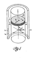
- a sample 10 is immersed in a static magnetic field B 0 , which is directed along the illustrative cylindrical sample Z axis, of a three-dimensional Cartesian coordinate system.
- Gradients in the X,Y and/or Z directions can be utilized, in conjunction with radio-frequency (RF) excitation pulses at the proper Larmor frequency, to evoke NMR response signals from desired nuclei in a slice, or slab, portion 11 of the sample.
- Sample slice 11 has a thickness AZ in the Z direction; the slice 11 can be through of as configured of sequential consecutive strips lla, each having a width AY, with each of the strips containing a multiplicity of volume elements. (voxels) 11b, of length AX.
- the slice, strips and voxels of the sample are selected by suitable application of magnetic field gradients G Z , G Y , G X , where and
- Means 12 may include: a superconducting (or resistive or permanent) magnet means for providing the static B O field, and used with or without superconducting and/or resistive shimming coils and/or passive magnetic shims for decreasing nonlinearities in the main B O field; magnetic field gradient-forming coil means; radio-frequency antennae; and the like, as well known to the art.
- a magnetic field portion B A which itself can be the result of a desired flow of current I A in means 12, can induce an eddy, or secondary, current contribution I B in an adjacent portion of a conductor, such as is found in means 12.
- the eddy current I B can be present at a non-zero magnitude at a time after the original magnetic field portion B A has decayed to an essentially zero magnitude. If present, the eddy;current I B will itself generate a magnetic field portion, or gradient, E B within volume 10, possibly at a time which causes interference with the excitation of the NMR signal or with the desired MMR imaging response signal itself, from the slice 11 of excited nuclear spins of the sample.
- additional pulsed magnetic field gradients are provided to oppose and substantially cancel the induced eddy current fields E B .
- the compensating gradient pulses include at least one of corrective magnetic field gradient pulses applied: during non-selective RF pulse signals; immediately subsequent to an initial magnetic field gradient application; during data acquisition time intervals; or during the presence of the magnetic field gradients themselves, to compensate for gradient-gradient crosstalk.
- a first form of correction signal is provided, as part of each magnetic field gradient signal sequence applied along one of the three Cartesian coordinate system axes, to oppose and substantially cancel eddy current fields induced by non-uniformity of the radio-frequency (RF) magnetic field applied to non-selectively invert the spins of nuclei in that slice 11 to be imaged.
- RF radio-frequency
- the effects of a non-uniform RF excitation field can be overcome by use of at least one substantially-constant-amplitude correction signal which is present during the non-selective RF signal pulse.
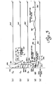
- correction signals will be illustrated as part of a spin-echo 2DFT sequence.
- the sequence commences with each gradient signal having an essentially zero-magnitude portion prior to commencement time to (i.e. as shown by the Z-axis gradient G Z signal portion 20a, the X-axis G X gradient portion 21a and the Y-axis Gy portion 22a), along with a substantially zero-magnitude radio-frequency signal portion 23a, of respective portions (a), (b), (c) and (d) of Figure 2.
- the imaging receiver has its data acquisition gate ( Figure 2, portion e) "closed", as shown by signal portion 24a.
- the imaging sequence commences at time t 0 , when the Z-axis gradient magnetic field rises to a magnitude, as in portion 20b, selected to determine the Z-axis midpoint of the slice at a desired distance from the coordinate system zero center defined in the sample imaging system.
- a substantially 90° selective RF pulse 23b (or the inverse thereof, e.g. pulse 23b', as required by the necessary phasing for that particular sequence) is applied to nutate the spins in a selected slice through 90°.
- Pulse 23b or 23b' reaches its peak amplitude at time t 2 and essentially finished time prior the time is essentially finished at time t 3 , prior to the time t 4 at which the Z gradient field slice-selection portion 20b ends.
- the selective RF pulse 23b or 23b' may have an envelope which is of the sinc-modulated, Gaussian-modulated or the like modulated envelope shape, to determine the slice thickness ⁇ Z and weighting, or edge "sharpness", thereof.
- the Z-axis magnetic field gradient G Z may be supplied, as in rephasing portion 20c, with a polarity opposite to the polarity of portion 20b and with an amplitude such that substantially G Z (t ⁇ dt t5 G Z (t)dt.
- the Y-axis gradient G Y field can be applied with a peak amplitude chosen to spatially encode stripes lla of voxels with a Y-axis value of lobular portion 22b (or of that one of portions 22b-1, 22b-2, 22b-3;...) selected for that particular sequence;
- the X-axis G X gradient magnetic field is provided as a lobular portion 21b of peak amplitude sufficient to provide an NMR signal during data acquisition interval 24b in conjunction with RF pulse 23d and gradient portion 21d, as described in U.S. patent No. 4,471,306 issued September 11, 1984 and assigned to the same assignee as the present invention.
- the pulsed gradient magnetic fields G Z , G X and Gy signals are all essentially terminated; in the known spin-echo imaging sequence these signals would then be provided, in portions 20d, 21c and 22c, respectively, with essentially zero magnitude, such that the gradient magnitudes have definitely decayed to an essentially zero magnitude by the time t 6 at which a non-selective 180° RF pulse 23d is applied to the sample.
- the eddy current may itself provide an undesired, disturbing magnetic field gradient during the time interval from time t 5 to t 8 , and especially during the time interval from time t 6 to t 7 when non-selective RF pulse 23d is present.
- the presence of a non-zero gradient field during pulse signal portion 23d will cause a non-uniform excitation RF field to be present across at least part of the imaging volume and will, accordingly, deleteriously limit the imaging information in a direction related to that one of the axes then having a non-zero gradient magnetic field therealong.
- the eddy current-induced gradient magnetic fields present during a non-selective RF pulse are opposed and substantially cancelled by means of at least one gradient-compensating correction pulse.
- a first correction gradient magnetic field signal pulse 20d' can be provided, during the time interval between times t 5 and t 8 , in the Z-axis G Z gradient magnetic field signal.
- the Z-axis correction pulse 20d' is provided with an amplitude ZCOR and polarity selected to provide as uniform an excitation RF field as possible in the Z-direction responsive to the associated non-selective RF signal pulse 23d.
- an X-axis G X gradient magnetic field correction signal pulse 21c' can be provided with an amplitude XCOR
- a Y-axis Gy gradient magnetic field correction signal pulse 22c' can be provided with a magnitude YCOR.
- the values ZCOR, XCOR and/or YCOR are each adjusted such that the amplitude level (and polarity) of that gradient field correction pulse, which is at an essentially stable value between times t 6 and t 7 , is that amplitude (and polarity) necessary for opposing and substantially cancelling the eddy current-induced gradient magnetic field component along the associated coordinate axis.
- the correction signal amplitude XCOR, YCOR or ZCOR of portions 20d', 21c' or 22c', respectively, can each be adjusted to optimize the uniformity of excitation of the 180° non-selective RF pulse 23d, by adjusting for the maximum magnitude of the spin-echo response signal appearing during the time interval, from time t 9 to time t a , when the X-axis G X readout gradient magnetic field portion 21d is present and the data acquisition gate is open, as shown in portion 24b.
- the remainder of the sequence including the reduction of the X-axis readout gradient, at time t b , to the substantially zero initial value (as shown by portion 21a'), the return of the Gy gradient magnetic field to an essentially zero magnitude (in portion 22a') with or without the presence of a spoiler portion 22e used for randomizing any residual transverse NMR magnetization (or one of portions 22e-1, 22e-2, 22e-3, ...), the substantially zero RF signal amplitude in portion 23a', and the closure of the data acquisition gate, as in portion 24a', are well known to the art.
- the amplitudes, polarity and duration of the at least one correction signal (and typically a correction signal along each of the three coordinate axes of the coordinate system selected for use) present during each occurrence of a non-selective RF pulse are selected to oppose and substantially cancel the induced eddy current magnetic field gradients.
- a second form of correction signal is provided, as part of each magnetic field gradient signal sequence applied along at least one of the three Cartesian coordinate system axes, to oppose and substantially cancel any deleterious magnetic field responsive to an eddy current induced by a non-selective RF pulse.
- the eddy-current-cancelling correction signal can only be applied when the correction signal will not interfere with any data acquisition portion of the imaging sequence.
- This second form of correction signal is illustrated as part of an NMR chemical shift spectroscopy imaging sequence, wherein a narrow bandwidth RF magnetic field must be applied to the sample in the absence of any magnetic field gradient to selectively irradiate a particularly chemical-shift resonance to suppress that resonance from a desired chemical-shift spectrum response signal.
- the sequence will be seen to be, at least in its initial portions, similar to the spin-echo 2DFT sequence of figure 2. Thus, the sequence commences with each gradient signal having an essentially zero-magnitude portion prior to commencement time to (e.g.
- the system receiver has a "closed" data acquisition gate signal portion 34a (portion e of Figure 2) and is therefore initially disabled from receiving any response signals.
- the imaging sequence commencing at time t 0 , performs, at least through time t 5 , in the same manner as the sequence of Figure 2.
- the sequence through time t b performs in substantially identical manner to the performance of the non-corrected sequence described with respect to Figure 2.
- this original sequence while having a substantially zero-magnitude portion 31e for the X-axis gradient G X signal at the end of the read-out gradient portion 31d, includes a chemical-selective RF pulse portion 33f.
- the chemical-selective pulse signal 33f is a narrow bandwidth RF pulse which must be applied in the absence of a magnetic field gradient to selectively irradiate at least one undesired chemically-shifted resonance, such that the selected resonance(s) can be suppressed from the chemical-shift spectrum information obtained in the initial portions of the next-subsequent application of the data-collection sequence.
- eddy-current-induced magnetic field gradient(s) could be compensated for by utilizing the XCOR,YCOR and ZCOR correction signals applied during the time interval from time t d to time t (described with reference to Figure 2), to limit each eddy-current-induced gradient field value to less than the value of the maximum tolerable induced gradient along the associated axis; however, a typical narrow-bandwidth chemical-selective irradiation pulse is of relatively long duration, e.g.
- undesirable gradient magnetic fields responsive to eddy-currents induced during a non-selective RF pulse, are opposed and substantially cancelled by means of at least one gradient-compensating correction pulse applied immediately subsequent to an initial application of an associated gradient magnetic field.
- the illustrated signal sequence assumes compensation is required only for one gradient magnetic field, e.g. the X-axis gradient magnetic field G X ; it should be understood that similar corrections for the other two gradient magnetic fields, e.g.
- the Y-axis gradient magnetic field Gy and/or the Z-axis gradient magnetic field G Z could not be provided in the Figure 3 sequence prior to time t a since the existence of corrections of this type prior to the data acquisition portion 34b would deleteriously interfere with the desired NMR signal to be obtained in that time interval between time t 9 and time t a . Accordingly, the eddy currents to be compensated for here are those persisting after time t a , and any corrective actions must be taken subsequent to the data acquisition interval.
- the G X imaging gradient portion 31d is present with some amplitude XA during a time interval of duration T s , commencing at time t 8 and terminating at time t b .
- Correction pulse 31e' has an amplitude XA' substantially equal to the amplitude XA of the gradient magnetic field pulse 31d applied substantially immediately prior to the compensation pulse.
- the polarity of gradient correction pulse 31e' is that polarity necessary to allow pulse 31e' to "suck out" the tainting effects of the previously induced eddy-current(s) and is typically opposite to the polarity of the readout pulse 31d.
- Compensation pulse 31e' thus has a time duration T s ' (commencing at time t b and terminating at time t c ) typically less than or equal to the time duration T of the pulse 31d being compensated for and is adjusted to cancel the effects of pulse 31d and so provide a uniform field during application of the chemical selective pulse 33f.
- pulse 31e' must terminate prior to the application of the chemical-selective RF pulse 33f which commences at time t d .
- a third form of correction signal is provided, as part of each magnetic field gradient signal sequence applied along at least one of the three Cartesian coordinate system axes, to oppose and substantially cancel an error induced in a gradient magnetic field by an eddy current itself caused by the temporal asymmetry of that gradient magnetic field present during a 180° selective RF pulse.
- the gradient magnetic field applied during a slice-selective 180° (or v-radian) RF pulse is desirably time-symmetrical about the temporal center of that selective pulse.
- the gradient magnetic field rise time is different from the gradient magnetic field fall time, or for other, similar temporal non-symmetries to occur.
- the time interval required for the gradient magnetic field to increase from its rest value to its maximum value is not equal to the time interval required for the gradient magnetic field to decrease from the maximum value to the same rest value.
- correction signals are illustrated as part of a localized chemical-shift imaging sequence.
- the three gradient signals, the RF signal and the NMR response signal are all at a substantially zero level, as shown in respective portions 40a, 41a, 42a, 43a,and 44a, of portions (a)-(e) of Figure 4.
- the Z-axis gradient magnetic field G Z rises to a slice-selection magnitude, in portion 40b, at the start of a Z-axis gradient time interval T Z , from time t 0 to time t 4 ; during this time interval a 90° RF pulse 43b occurs, determining the Z-axis midpoint position and spread ⁇ Z of the slice for which a chemical-shift image is to be provided.
- non-zero portions of the RF excitation signal are shown as "transmission gated” functions herein, although modulation by a non-rectangular envelope function (such as the sinc-function modulation depicted as 33b in Figure 3) during these gated-on time intervals is more common.
- a re-phasing portion 40c is provided in the Z-axis magnetic field gradient G Z , between time t 4 and time t s ; a response signal portion 44b may occur responsive to re-phasing portion 40c, but is ignored.
- a Y-axis selective gradient Gy portion 41b is provided for a time interval T Y , e.g.
- a 180° selective RF pulse 43d is provided, to select a Y direction stripe lla from which data is to be acquired.
- a X-axis gradient magnetic field G X portion 42b is then provided, during a time interval starting at a time t b and ending at a time t , wherein a second 180° selective g RF pulse 43f is provided, to select the X-axis location of the voxel llb along the Y stripe lla selected by gradient portion 41b. It is this voxel from which the localized chemical-shift image data will be provided as a response spin-echo signal 44f, responsive to this repetition of the imaging sequence.
- both of the gradient magnetic field portions 41b or 42b are temporal asymmetric, especially during the respective time interval (from t 7 to t8 or from t d to t e , respectively) when the associated 180° selective RF pulse 43d or 43f, respectively, is present, compensation for such temporal asymmetry can be provided at the same time that eddy-current compensation is provided by a compensation pulse following immediately subsequent to an initial application of the associated gradient magnetic field.
- each gradient magnetic field signal present during a selective 180° pulsed RF magnetic field is followed by an opposite-polarity compensation gradient pulse provided along that same axis of the field system.
- the compensation gradient signal has an amplitude and duration selected to oppose and substantially cancel any asymmetry in the gradient signal applied during the selective time interval. Accordingly, in the illustrative example, any asymmetry in the Y-axis gradient magnetic field Gy portion 41b is compensated for by applying a gradient signal portion 41c', substantially immediately thereafter, in the time interval T Y ' (from time t 9 to time t a ), with a polarity (e.g.
- the asymmetry correction pulse 41c' terminates prior to the time at which a next pulse (or set of pulses) is applied to any gradient field axis, e.g. before the time t d when the X-axis gradient magnetic field G X portion 42b commences.
- the amplitude and duration of the compensating pulse are adjusted to maximize the corresponding echo signal refocused by the respective 180° selective RF pulse signal, e.g. amplitude YB and duration T..' are adjusted to maximize the echo signal 44d.
- a compensation pulse 42c' commences at a time t g at which the pulse (e.g. pulse 42b) to be compensated for terminates and lasts for a time interval T X ' (e.g. from time t g to time t h ); pulse 42c' has an amplitude XE and a polarity selected to oppose and substantially cancel any gradient asymmetry along the associated axis (e.g. the X-axis).
- compensation pulses e.g. compensation pulse 42c'
- these compensation pulses occur during the evolution of the NMR response signal and prior to data acquisition (e.g. in the interval from time t f and time t i )
- extreme care in setting of the compensation pulse parameters must be exercised, to prevent excessive disturbance of the response signal, and subsequent loss of response data.
- This form of correction signal is illustrated as part of a chemically-selective planar 2DFT imaging sequence, wherein (as in the signal sequence of Figure 3) a narrow bandwidth RF magnetic field is applied to the sample in the absence of any magnetic field gradient to selectively irradiate a particular chemical-shift resonance to suppress that resonance from the response signal and thereby generate an image of a selected chemically shifted species.
- the sequence will be seen, in the portions from commencement time t 0 through time t.1, to be similar to the 2DFT sequences previously discussed.
- the undesirable gradient magnetic fields present during response signal data acquisition responsive to eddy-currents induced prior to the data acquisition time interval, are opposed and substantially cancelled at least during the data acquisition time interval by adding a gradient-compensating correction pulse signal to at least one of the imaging magnetic field gradients, at least during the data acquisition time interval.
- Each correction pulse has a polarity opposite to the polarity of the associated gradient error to be compensated for, and has a time-varying amplitude established to substantially cancel the effect of the time-decaying eddy-current-induced gradient during that data acquisition time interval.
- the illustrated signal sequence collects response data for all voxels in the selected plane, spatically resolved in the X-direction by virtue of the non-zero X-axis gradient magnetic field G X spatial-encoding portion 51d.
- the respective Z-axis and Y-axis gradient magnetic fields G Z and Gy should have respective essentially-zero amplitudes, as in respective portions 50e and 52d.
- each pre-existing eddy current (being caused by a gradient field variation occurring prior to time t 7 ) is exponentially decaying, generally with a different time constant for that field component parallel to each different one of the coordinate system axes (responsive to the unavoidable inhomogeneities, in that axis direction, in the investigatory sample, the investigation system and the like).
- each pre-existing eddy current is exponentially decaying, generally with a different time constant for that field component parallel to each different one of the coordinate system axes (responsive to the unavoidable inhomogeneities, in that axis direction, in the investigatory sample, the investigation system and the like).
- the Z-axis gradient magnetic field G Z is provided with a first gradient correcting signal portion 50e', having an initial amplitude Z 0 , a time constant T Z and a polarity (e.g. positive polarity) selected such that the time-varying eddy-current-induced field is opposed and substantially cancelled (and the desired, e.g. essentially zero, amplitude is obtained) at least during the time interval of gate signal 54b.
- a first gradient correcting signal portion 50e' having an initial amplitude Z 0 , a time constant T Z and a polarity (e.g. positive polarity) selected such that the time-varying eddy-current-induced field is opposed and substantially cancelled (and the desired, e.g. essentially zero, amplitude is obtained) at least during the time interval of gate signal 54b.
- the desired (e.g. essentially zero) amplitude of the Y-axis gradient magnetic field Gy portion 52d is provided by utilization of a compensation signal pulse portion 52d', having a polarity (e.g. negative polarity), an initial amplitude y o and a time constant T y all selected to cause the actual Y-axis gradient field to have the substantially zero amplitude assumed for portion 52d.
- a compensation signal pulse portion 52d' having a polarity (e.g. negative polarity), an initial amplitude y o and a time constant T y all selected to cause the actual Y-axis gradient field to have the substantially zero amplitude assumed for portion 52d.
- any decaying eddy-field-induced gradient field error portion must be compensated for by an additional time-decaying portion 51d', itself having an initial polarity (e.g. positive polarity), an initial amplitude X 0 and a time constant T X all selected to cause the actual X-axis gradient magnetic field within the sample to have a substantially constant actual magnitude during the data acquisition time interval.
- an initial polarity e.g. positive polarity
- T X time constant
- each of the correction gradient magnetic fields G X ', G y ' and Gz ' is of the form: These correction terms are added to any non-zero constant amplitude gradient fields so as to generate net applied magnetic field gradients G X , G Y . and G Z during this time interval.
- the initial amplitude, polarity and/or time constant of at least one of the three gradient magnetic field correction signals may require modification to provide the required degree of compensation for the undesired eddy-current-induced error gradients.
- additional portions of each imaging sequence can be provided; these additional portions can include "spoiler" portions 52e, 52e-1, 52e-2, 52e-3,... having amplitudes established by the amplitude of an associated lobular portion 52b, 52b-1, 52b-2, 52b-3,...
- eddy-current-compensating "sucker” pulses e.g. pulse 52f', thereafter, but prior to subsequent selective signals
- chemical-selective irradiation pulses such as the suppression pulse 53d; and the like.
- a fifth form of correction signal is provided, as part of each magnetic field gradient signal sequence applied along at least one pair of the Cartesian coordinate system axes, to oppose and substantially cancel an error induced in a gradient magnetic field by cross talk between the means utilized for forming the gradient magnetic fields along the involved pair of axes.
- the gradient magnetic fields along each pair of axes are defined as orthogonal to one another.
- real physical means for forming the pair of gradient fields such as pairs of coils and the like may generate a pair of gradient magnetic fields which are non-orthogonal.
- the non-orthogonality causes a gradient-magnetic-field-inducing current in one portion of the (coil) generating means to induce not only a gradient along the desired axis, but also an undesired gradient portion along the orthogonal axis, thus altering the gradient value along that orthogonal axis and degrading, distorting or confusing the spatial imaging information to be obtained.
- This "cross-talk" between the means generating each field along each axis of the gradient magnetic field system will be seen to be perhaps the only one of the problems described herein which can be completely alleviated by physical reconstruction of the involved gradient- field-forming means.
- a gradient magnetic field having a cross-talk contribution thereto from another gradient magnetic field to the field system is individually compensated by application of a correction pulse signal of amplitude, waveshape and polarity selected to oppose and substantially eliminate the cross-talk-induced field portion.
- the corrective gradient signal may vary proportional to the gradient field acting as the cross-talk source, when that source gradient field is changed in signal characteristics, e.g. amplitude, signal shape, polarity, and the like.
- the cross-talk correction signals are illustrated as part of a 2DFT imaging sequence, similar to the imaging sequence of Figure 2 except with respect to the compensating gradient field pulses along X and Y axes. It will be seen that, during the phase-encoding time interval from time t 4 to time t s , there is cross-talk from the Y-axis gradient magnetic field Gy lobular portion 62b to the X-axis gradient magnetic field GX desired lobular portion 61b.
- the illustrated cross-talk effect is a subtractive phenomenon (although it should be clearly understood that an additive effect may equally as well obtain), whereby the actual X-axis gradient-forming signal must be of greater-than-expected amplitude, so that an increased amplitude portion 61b' is utilized.
- the means typically utilized for forming a gradient magnetic field have time constants which are generally shorter than the time constants of eddy-current fields induced in a physically larger magnet structure, the cross-talk time constants themselves will be relatively short (generally on the order of one millisecond) whereby a constant-magnitude correction signal cannot be utilized. Accordingly, the cross-hatched portion between desired signal portion 61b and actually-utilized portion 61b' indicates that a time-varying cross-talk correction signal pulse, of maximum amplitude XC, is required to compensate for this particular portion of the cross-talk phenomenon.
- the presence of a signal along one system axis such as the X-axis gradient magnetic field G X portion 61d present during data acquisition ( between at least times t 9 and t a ), can have an effect upon the Y-axis gradient magnetic field Gy portion 62c, which is ideally of zero magnitude during the same time interval, and which effect can be actually compensated for by the short-time-constant cross-talk compensation pulse signal portion 62c'.
- the amplitude, polarity and time constant of this cross-talk compensation pulse can be empirically established to oppose and substantially cancel the cross-talk effect of a gradient field signal along each axis and due to the gradient field signal along each remaining different one of the axes.
Landscapes
- Physics & Mathematics (AREA)
- Condensed Matter Physics & Semiconductors (AREA)
- General Physics & Mathematics (AREA)
- High Energy & Nuclear Physics (AREA)
- Health & Medical Sciences (AREA)
- General Health & Medical Sciences (AREA)
- Nuclear Medicine, Radiotherapy & Molecular Imaging (AREA)
- Radiology & Medical Imaging (AREA)
- Engineering & Computer Science (AREA)
- Signal Processing (AREA)
- Magnetic Resonance Imaging Apparatus (AREA)
Applications Claiming Priority (2)
| Application Number | Priority Date | Filing Date | Title |
|---|---|---|---|
| US06/760,222 US4647858A (en) | 1985-07-29 | 1985-07-29 | Methods for overcoming transient magnetic field inhomogeneity in nuclear magnetic resonance imaging |
| US760222 | 1985-07-29 |
Publications (2)
| Publication Number | Publication Date |
|---|---|
| EP0210562A2 true EP0210562A2 (fr) | 1987-02-04 |
| EP0210562A3 EP0210562A3 (fr) | 1987-09-09 |
Family
ID=25058457
Family Applications (1)
| Application Number | Title | Priority Date | Filing Date |
|---|---|---|---|
| EP86109943A Withdrawn EP0210562A3 (fr) | 1985-07-29 | 1986-07-19 | Procédés pour surmonter l'homogénéité transitoire du champ magnétique dans la formation d'images de résonance magnétique nucléaire |
Country Status (4)
| Country | Link |
|---|---|
| US (1) | US4647858A (fr) |
| EP (1) | EP0210562A3 (fr) |
| JP (1) | JPS6264351A (fr) |
| IL (1) | IL78669A0 (fr) |
Cited By (6)
| Publication number | Priority date | Publication date | Assignee | Title |
|---|---|---|---|---|
| EP0310434A3 (fr) * | 1987-09-30 | 1990-07-25 | Kabushiki Kaisha Toshiba | Système d'imagerie par résonance magnétique |
| EP0577188A1 (fr) * | 1992-06-29 | 1994-01-05 | Koninklijke Philips Electronics N.V. | Procédé et appareil d'imagerie par résonance magnétique |
| DE4325031C1 (de) * | 1993-07-26 | 1994-11-03 | Siemens Ag | Verfahren zur Erfassung von durch Gradienten verursachten Wirbelstrom-Magnetfeldern in einem Kernspinresonanzgerät |
| US5455512A (en) * | 1992-10-26 | 1995-10-03 | U.S. Philips Corporation | Eddy current compensation in magnetic resonance imaging |
| EP0735379A3 (fr) * | 1995-03-28 | 1997-02-26 | Yokogawa Medical Syst | Appareil d'IRM |
| DE19814677B4 (de) * | 1997-07-01 | 2009-10-08 | General Electric Co. | Korrektur einer durch Maxwell-Terme verursachten Verschlechterung eines Axial-Bild-Signals |
Families Citing this family (21)
| Publication number | Priority date | Publication date | Assignee | Title |
|---|---|---|---|---|
| IL79076A (en) * | 1986-06-10 | 1989-10-31 | Elscint Ltd | Restricted volume imaging |
| JPS63109849A (ja) * | 1986-10-29 | 1988-05-14 | 株式会社日立メディコ | Nmrイメ−ジング装置 |
| DE3730148A1 (de) * | 1987-09-09 | 1989-03-30 | Bruker Medizintech | Verfahren zum erzeugen von spin-echo-impulsfolgen mit einem kernspin-tomographen und zur durchfuehrung des verfahrens ausgebildeter kernspin-tomograph |
| JPH03501090A (ja) * | 1987-11-05 | 1991-03-14 | ユニバーシティー オブ クイーンスランド | Nmr分光器の磁界均質化方法 |
| US4812797A (en) * | 1988-03-22 | 1989-03-14 | General Electric Company | Compensation coil for temporal drift of a superconducting magnet |
| EP0351446B1 (fr) * | 1988-07-22 | 1992-04-01 | Siemens Aktiengesellschaft | Séquence d'impulsion pour un appareil d'imagerie RMN |
| JP2580747B2 (ja) * | 1988-11-28 | 1997-02-12 | 株式会社島津製作所 | Mri装置の傾斜磁場印加方法 |
| US4965521A (en) * | 1989-08-11 | 1990-10-23 | Spectroscopy Imaging Systems | Method and apparatus for compensating eddy current effects in a magnetic resonance device having pulsed magnetic field gradients |
| JPH03224538A (ja) * | 1990-01-31 | 1991-10-03 | Hitachi Medical Corp | 一次の静磁場不均一を補正して計測する過程を備えたmri装置 |
| NL9100138A (nl) * | 1991-01-28 | 1992-08-17 | Philips Nv | Magnetische resonantie werkwijze en inrichting ter reductie van beeldfouten in een magnetisch resonantiebeeld. |
| DE69326202T2 (de) * | 1992-06-29 | 2000-04-13 | Koninklijke Philips Electronics N.V., Eindhoven | Verfahren und Gerät zur Kernresonanzabbildung |
| US5530356A (en) * | 1992-07-20 | 1996-06-25 | Kabushiki Kaisha Toshiba | Method and apparatus for generating magnetic fields for nuclear magnetic resonance imaging with cross-talk compensation |
| DE19943372C2 (de) * | 1999-09-10 | 2001-07-19 | Siemens Ag | Gradientenspulensystem für ein Magnetresonanztomographiegerät |
| DE10203279C1 (de) * | 2002-01-29 | 2003-10-09 | Bruker Biospin Ag | Verfahren zur Beeinflussung des homogenen statischen Magnetfelds in einer NMR-Apparatur und zugehöriger NMR-Resonator |
| DE102008004256B4 (de) * | 2008-01-14 | 2010-01-07 | Siemens Aktiengesellschaft | SAR-optimierte Ansteuerung eines Spulenarrays |
| JP5416960B2 (ja) * | 2008-12-17 | 2014-02-12 | 株式会社東芝 | 磁気共鳴イメージング装置 |
| WO2010074057A1 (fr) * | 2008-12-26 | 2010-07-01 | 株式会社 日立メディコ | Appareil d'imagerie par résonance magnétique et procédé d'ajustement de séquence d'impulsions |
| JP2012040362A (ja) * | 2010-07-23 | 2012-03-01 | Toshiba Corp | 磁気共鳴イメージング方法、磁気共鳴イメージング装置およびその制御装置 |
| DE102013202217B4 (de) | 2013-02-12 | 2015-05-28 | Siemens Aktiengesellschaft | MR-Anlage mit gepulsten Ausgleichsmagnetfeldgradienten |
| DE102018205867A1 (de) * | 2018-04-18 | 2019-10-24 | Siemens Healthcare Gmbh | Verfahren und Vorrichtung zur Erstellung einer Pulssequenz zur Ansteuerung eines Magnetresonanztomographie-Systems |
| EP3640661B1 (fr) * | 2018-10-16 | 2025-03-05 | Siemens Healthineers AG | Procédé et système irm pour la compensation active des champs magnétiques induits par courants de foucault dans l'imagerie par résonance magnétique |
Family Cites Families (10)
| Publication number | Priority date | Publication date | Assignee | Title |
|---|---|---|---|---|
| US4180769A (en) * | 1978-02-21 | 1979-12-25 | Varian Associates, Inc. | Superconducting solenoid with compensation for axial gradients |
| GB1578910A (en) * | 1978-05-25 | 1980-11-12 | Emi Ltd | Imaging systems |
| US4284950A (en) * | 1978-08-05 | 1981-08-18 | E M I Limited | Imaging systems |
| US4599565A (en) * | 1981-12-15 | 1986-07-08 | The Regents Of The University Of Calif. | Method and apparatus for rapid NMR imaging using multi-dimensional reconstruction techniques |
| US4484138A (en) * | 1982-07-01 | 1984-11-20 | General Electric Company | Method of eliminating effects of spurious free induction decay NMR signal caused by imperfect 180 degrees RF pulses |
| US4506223A (en) * | 1982-11-22 | 1985-03-19 | General Electric Company | Method for performing two-dimensional and three-dimensional chemical shift imaging |
| US4585993A (en) * | 1983-12-14 | 1986-04-29 | General Electric Company | Method for selective NMR imaging of chemically-shifted nuclei |
| US4591789A (en) * | 1983-12-23 | 1986-05-27 | General Electric Company | Method for correcting image distortion due to gradient nonuniformity |
| US4612504A (en) * | 1984-11-21 | 1986-09-16 | General Electric Company | Method for removing the effects of baseline error components in NMR imaging applications |
| FR2574551B1 (fr) * | 1984-12-12 | 1986-12-26 | Commissariat Energie Atomique | Procede de generation et de traitement de signaux pour l'obtention par resonance magnetique nucleaire d'une image exempte de distorsions a partir d'un champ de polarisation inhomogene |
-
1985
- 1985-07-29 US US06/760,222 patent/US4647858A/en not_active Expired - Lifetime
-
1986
- 1986-05-02 IL IL78669A patent/IL78669A0/xx unknown
- 1986-07-19 EP EP86109943A patent/EP0210562A3/fr not_active Withdrawn
- 1986-07-24 JP JP61172966A patent/JPS6264351A/ja active Pending
Cited By (8)
| Publication number | Priority date | Publication date | Assignee | Title |
|---|---|---|---|---|
| EP0310434A3 (fr) * | 1987-09-30 | 1990-07-25 | Kabushiki Kaisha Toshiba | Système d'imagerie par résonance magnétique |
| EP0577188A1 (fr) * | 1992-06-29 | 1994-01-05 | Koninklijke Philips Electronics N.V. | Procédé et appareil d'imagerie par résonance magnétique |
| US5455512A (en) * | 1992-10-26 | 1995-10-03 | U.S. Philips Corporation | Eddy current compensation in magnetic resonance imaging |
| DE4325031C1 (de) * | 1993-07-26 | 1994-11-03 | Siemens Ag | Verfahren zur Erfassung von durch Gradienten verursachten Wirbelstrom-Magnetfeldern in einem Kernspinresonanzgerät |
| EP0735379A3 (fr) * | 1995-03-28 | 1997-02-26 | Yokogawa Medical Syst | Appareil d'IRM |
| US5729139A (en) * | 1995-03-28 | 1998-03-17 | Ge Yokogawa Medical Systems, Ltd. | MRI apparatus |
| CN100465659C (zh) * | 1995-03-28 | 2009-03-04 | 通用电器横河医疗系统株式会社 | 磁共振成象装置 |
| DE19814677B4 (de) * | 1997-07-01 | 2009-10-08 | General Electric Co. | Korrektur einer durch Maxwell-Terme verursachten Verschlechterung eines Axial-Bild-Signals |
Also Published As
| Publication number | Publication date |
|---|---|
| US4647858A (en) | 1987-03-03 |
| JPS6264351A (ja) | 1987-03-23 |
| EP0210562A3 (fr) | 1987-09-09 |
| IL78669A0 (en) | 1986-08-31 |
Similar Documents
| Publication | Publication Date | Title |
|---|---|---|
| US4647858A (en) | Methods for overcoming transient magnetic field inhomogeneity in nuclear magnetic resonance imaging | |
| EP0106226B1 (fr) | Méthodes d'isolation sélective d'un volume pour la mise en oeuvre d'une analyse spectroscopique localisée par RMN et appareils pour la mise en oeuvre de ces méthodes | |
| US5391990A (en) | Iterative shimming method for a basic field magnet of a nuclear magnetic resonance tomography apparatus | |
| EP0109633B1 (fr) | Méthodes et appareil pour la formation d'images bi- et tridimensionnelles utilisant le déplacement chimique | |
| EP0144871B1 (fr) | Méthode et appareil d'imagerie sélective par RMN de noyaux présentant un déplacement chimique | |
| US5450010A (en) | Magnetic resonance imaging method and apparatus employing eddy current compensation by modification of gradient size | |
| EP0188006B1 (fr) | Procédé pour renverser l'aimantation transversale résiduelle créée par l'application des gradients de champ magnétique de codage de phase,et dispositif | |
| US5570019A (en) | Method for magnetic resonance spectroscopic imaging with multiple spin-echoes | |
| US5455512A (en) | Eddy current compensation in magnetic resonance imaging | |
| US4623844A (en) | NMR inhomogeneity compensation system | |
| US5168232A (en) | Method for rapid magnet shimming | |
| US5237273A (en) | Interleaved acquisition of multi-slice NMR data | |
| US5557202A (en) | Method and system for magnetic resonance imaging | |
| US4553096A (en) | Nuclear magnetic resonance method and apparatus | |
| US5677626A (en) | System for magnetic resonance imaging | |
| US5064638A (en) | Simultaneous multinuclear magnetic resonance imaging and spectroscopy | |
| EP0182107A1 (fr) | Procédé pour réduire les composants d'erreur de la ligne de base de signaux de RMN | |
| EP0161366A2 (fr) | Procédé et appareil de résonance magnétique nucléaire | |
| US6545476B1 (en) | Method for shimming a magnet system of a MR tomography apparatus and MR tomography apparatus for the implementation of the method | |
| EP0106551B1 (fr) | Procédé et appareil à résonance magnétique nucléaire | |
| US5371465A (en) | Inspection method and apparatus using nuclear magnetic resonance (NMR) | |
| EP0541636B1 (fr) | Ameliorations concernant la spectroscopie et l'imagerie par resonance magnetique | |
| US6057686A (en) | Shifted echo MR method and device | |
| DE19906859B4 (de) | Magnetresonanz-Spektroskopieabbildung mit verringertem chemischen Verschiebungsfehler | |
| EP0850422B1 (fr) | Appareil de rm comprenant des moyens pour la reduction des effets des gradients concomitants |
Legal Events
| Date | Code | Title | Description |
|---|---|---|---|
| PUAI | Public reference made under article 153(3) epc to a published international application that has entered the european phase |
Free format text: ORIGINAL CODE: 0009012 |
|
| AK | Designated contracting states |
Kind code of ref document: A2 Designated state(s): CH DE FR GB LI NL |
|
| PUAL | Search report despatched |
Free format text: ORIGINAL CODE: 0009013 |
|
| AK | Designated contracting states |
Kind code of ref document: A3 Designated state(s): CH DE FR GB LI NL |
|
| STAA | Information on the status of an ep patent application or granted ep patent |
Free format text: STATUS: THE APPLICATION IS DEEMED TO BE WITHDRAWN |
|
| 18D | Application deemed to be withdrawn |
Effective date: 19880310 |
|
| RIN1 | Information on inventor provided before grant (corrected) |
Inventor name: BOTTOMLEY, PAUL ARTHUR |