EP0210652A2 - Elément de protection de surfaces partielles de pièces à usiner - Google Patents
Elément de protection de surfaces partielles de pièces à usiner Download PDFInfo
- Publication number
- EP0210652A2 EP0210652A2 EP86110483A EP86110483A EP0210652A2 EP 0210652 A2 EP0210652 A2 EP 0210652A2 EP 86110483 A EP86110483 A EP 86110483A EP 86110483 A EP86110483 A EP 86110483A EP 0210652 A2 EP0210652 A2 EP 0210652A2
- Authority
- EP
- European Patent Office
- Prior art keywords
- protective
- treated
- deformable
- partial surfaces
- protecting element
- Prior art date
- Legal status (The legal status is an assumption and is not a legal conclusion. Google has not performed a legal analysis and makes no representation as to the accuracy of the status listed.)
- Granted
Links
Images
Classifications
-
- B—PERFORMING OPERATIONS; TRANSPORTING
- B65—CONVEYING; PACKING; STORING; HANDLING THIN OR FILAMENTARY MATERIAL
- B65D—CONTAINERS FOR STORAGE OR TRANSPORT OF ARTICLES OR MATERIALS, e.g. BAGS, BARRELS, BOTTLES, BOXES, CANS, CARTONS, CRATES, DRUMS, JARS, TANKS, HOPPERS, FORWARDING CONTAINERS; ACCESSORIES, CLOSURES, OR FITTINGS THEREFOR; PACKAGING ELEMENTS; PACKAGES
- B65D59/00—Plugs, sleeves, caps, or like rigid or semi-rigid elements for protecting parts of articles or for bundling articles, e.g. protectors for screw-threads, end caps for tubes or for bundling rod-shaped articles
- B65D59/02—Plugs
Definitions
- the invention relates to a protective element for covering partial areas of a workpiece to be machined, consisting of a plastically deformable material, for example graphite, which is resistant to temperatures of up to 1000 ° C.
- a protective element which consists of a material which is temperature-resistant and plastically deformable at least up to 1000 ° C.
- Graphite is preferably suitable as the protective material.
- Such an element is described in DE-OS 33 15 894.
- it has proven difficult to press a threaded element into a long or long element in relation to its diameter.
- significantly more graphite is consumed than would be necessary due to the thread dimensions alone.
- a certain limit for the ratio of element height to element diameter (H / D) must be observed. This in turn means the production of protective elements of different wall thicknesses for threads of different lengths.
- the invention is based on the object to remedy this and to form a protective element according to the generic term so that even with a large ratio of thread length to diameter, pressing is possible without a high cost of materials.
- the solution according to the invention is characterized in that the deformable material is provided with a metal reinforcement.
- This can be tubular or ring-shaped, wherein the deformable protective material can be arranged in the region of the ends of the metal reinforcement in the form of outer or inner rings.
- the deformable protective material enclose the metal reinforcement in the form of a jacket as an outer or inner film.
- Steel is particularly well suited as a material for the metal reinforcement, which in particular permits the processing of the protective elements in an automatic machine or enables the automatic pressing of the protective elements in the first place.
- the arrangement of the protective material, for example graphite in the form of rings, material is saved considerably without fear of the penetration of liquid material such as zinc and the like into a thread to be protected.
- the formation of a protective element in the form of a tubular steel core with an outer or inner film made of protective material has also been found to be effective.
- the tubular protective element is simply pressed into a threaded bore or pushed over an external thread, and a part of the protective element can protrude outward beyond the threaded end. Installation is both extremely simple and suitable for different thread depths and inexpensive to manufacture thanks to the small amount of protective material.
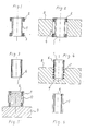
- Rings 2 and 3 made of graphite are attached to the outer circumference of a tubular reinforcement 1 (FIG. 1).
- the tube 1 with its ring elements 2, 3 is pressed into the threaded bore 4 of a workpiece 5, as shown in FIG. 2.
- FIG. 4 Another embodiment of a protective element is shown in FIG. This element can also be pressed into a threaded bore 7 of a workpiece 8, similar to FIG. 2. 4 is a blind hole into which the element with the film 6 is pressed until the inner end of the blind hole is reached. The upper end of the protective element can protrude from the workpiece.
- a workpiece 9 provided with a peg-shaped external thread is enclosed by a protective element, the tubular reinforcement 1 of which is equipped with rings made of graphite.
- the rings 2, 3 are arranged on the inner circumference of the reinforcement and again in the region of the ends.
- the protective element according to FIG. 6 can be processed in the same way with a tubular reinforcement 1 and an inner film 6.
Landscapes
- Engineering & Computer Science (AREA)
- Mechanical Engineering (AREA)
- Fuses (AREA)
- Forging (AREA)
- Chemically Coating (AREA)
- Superconductors And Manufacturing Methods Therefor (AREA)
- Electroplating Methods And Accessories (AREA)
- Protection Of Pipes Against Damage, Friction, And Corrosion (AREA)
- Coating With Molten Metal (AREA)
Priority Applications (1)
| Application Number | Priority Date | Filing Date | Title |
|---|---|---|---|
| AT86110483T ATE63882T1 (de) | 1985-08-02 | 1986-07-29 | Schutzelement zum abdecken von teilbereichen an zu bearbeitenden werkstuecken. |
Applications Claiming Priority (2)
| Application Number | Priority Date | Filing Date | Title |
|---|---|---|---|
| DE19853527703 DE3527703A1 (de) | 1985-08-02 | 1985-08-02 | Schutzelement zum abdecken von teilbereichen an zu bearbeitenden werkstuecken |
| DE3527703 | 1985-08-02 |
Publications (3)
| Publication Number | Publication Date |
|---|---|
| EP0210652A2 true EP0210652A2 (fr) | 1987-02-04 |
| EP0210652A3 EP0210652A3 (en) | 1988-08-03 |
| EP0210652B1 EP0210652B1 (fr) | 1991-05-29 |
Family
ID=6277464
Family Applications (1)
| Application Number | Title | Priority Date | Filing Date |
|---|---|---|---|
| EP86110483A Expired - Lifetime EP0210652B1 (fr) | 1985-08-02 | 1986-07-29 | Elément de protection de surfaces partielles de pièces à usiner |
Country Status (3)
| Country | Link |
|---|---|
| EP (1) | EP0210652B1 (fr) |
| AT (1) | ATE63882T1 (fr) |
| DE (1) | DE3527703A1 (fr) |
Families Citing this family (4)
| Publication number | Priority date | Publication date | Assignee | Title |
|---|---|---|---|---|
| DE3912666A1 (de) * | 1989-04-18 | 1990-10-25 | Bayerische Motoren Werke Ag | Abdeckvorrichtung gegen zinkbeschichten von flaechenteilen an bad-feuerverzinkten bauteilen aus eisenwerkstoff |
| DE4315478A1 (de) * | 1993-05-10 | 1994-11-17 | Hermann Klein | Zinkabschlußhülse für Gewindemuffen, Gewindenippel, Schraubenbolzen, Muttergewindelöcher und Bohrungen |
| DE4338459C2 (de) * | 1993-11-11 | 2003-05-08 | Sgl Carbon Ag | Wärmeisolierender Hohlzylinder |
| DE202005014390U1 (de) * | 2005-09-15 | 2007-02-01 | Durferrit Gmbh | Vorrichtung zur Isolierung eines Oberflächenbereichs eines Werkstücks |
Family Cites Families (5)
| Publication number | Priority date | Publication date | Assignee | Title |
|---|---|---|---|---|
| CS160910B1 (fr) * | 1973-01-29 | 1975-05-04 | ||
| DE2939383A1 (de) * | 1979-09-28 | 1981-04-02 | Dreyfuß GmbH, 3111 Eimke | Vorrichtung zum schutz von hohlraeumen |
| DE8113177U1 (de) * | 1981-04-28 | 1981-08-13 | Mannesmann AG, 4000 Düsseldorf | Schutzkappe fuer Gewinderohre |
| DE8312888U1 (de) * | 1983-05-02 | 1984-08-09 | Daume, Achim, Dipl.-Ing., 3006 Burgwedel | Schutzelement fuer zu bearbeitende Werkstuecke |
| DE3315894C2 (de) * | 1983-05-02 | 1986-07-03 | Achim Dipl.-Ing. 3006 Burgwedel Daume | Schutzelement für zu bearbeitende Werkstücke |
-
1985
- 1985-08-02 DE DE19853527703 patent/DE3527703A1/de active Granted
-
1986
- 1986-07-29 AT AT86110483T patent/ATE63882T1/de not_active IP Right Cessation
- 1986-07-29 EP EP86110483A patent/EP0210652B1/fr not_active Expired - Lifetime
Also Published As
| Publication number | Publication date |
|---|---|
| DE3527703A1 (de) | 1987-02-12 |
| EP0210652B1 (fr) | 1991-05-29 |
| EP0210652A3 (en) | 1988-08-03 |
| ATE63882T1 (de) | 1991-06-15 |
| DE3527703C2 (fr) | 1987-08-13 |
Similar Documents
| Publication | Publication Date | Title |
|---|---|---|
| DE19820054B4 (de) | Radbefestiger | |
| DE2551704C2 (de) | Rohrkörper, bestehend aus einem Rohr aus synthetischem Material, welches von einem Verstärkungsrohr ummantelt ist | |
| DE3626009C2 (fr) | ||
| DE3539449C2 (fr) | ||
| DE3345487A1 (de) | Zylinderkopfdichtung | |
| DE3431789C2 (fr) | ||
| DE19652181A1 (de) | Vorrichtung zur Umwandlung einer Drehbewegung in eine geradlinige Bewegung | |
| WO1995018877A2 (fr) | Materiau de friction fritte pour elements a liaison par friction, elements ainsi realises | |
| EP0210652B1 (fr) | Elément de protection de surfaces partielles de pièces à usiner | |
| DE3628360C2 (fr) | ||
| DE2746071A1 (de) | Vorrichtung zum festlegen eines radialkugellagers | |
| EP0655295B1 (fr) | Corps métallique et procédé pour sa fabrication | |
| DE8135511U1 (de) | Spannzangenartiger Führungsaufbau für Drehmaschinen zum Führen von Staagenmaterial | |
| DD298216A5 (de) | Walze fuer stranggiessanlagen zum direkten giessen duenner baender aus fluessigem metall | |
| DE2356135C3 (de) | Einlagige zylindrische Induktionsspule | |
| DE2702876C3 (de) | Drehrohrofen mit einer Anzahl von Planetenkühlrohren | |
| DE3023543C2 (de) | Verfahren zur Herstellung eines Langstabisolators | |
| DE2343836C3 (de) | Endstück zum Schutz der Enden von Rohren gegen Beschädigungen | |
| DE3315894C2 (de) | Schutzelement für zu bearbeitende Werkstücke | |
| DE2409809A1 (de) | Gewindeschneidkluppe | |
| DE29610620U1 (de) | Aufschweißbares Befestigungselement | |
| DE8500986U1 (de) | Glühkerze | |
| DE3518705A1 (de) | Walze oder rolle | |
| DE2345610C3 (de) | Matrize zum Strangpressen oder Ziehen | |
| DE8806545U1 (de) | Vorrichtung zur kontrollierten Beeinflussung des Innen- und/oder Außendurchmessers beim Abkühlvorgang von zu härtenden Werkstücken |
Legal Events
| Date | Code | Title | Description |
|---|---|---|---|
| PUAI | Public reference made under article 153(3) epc to a published international application that has entered the european phase |
Free format text: ORIGINAL CODE: 0009012 |
|
| AK | Designated contracting states |
Kind code of ref document: A2 Designated state(s): AT BE FR GB IT NL |
|
| PUAL | Search report despatched |
Free format text: ORIGINAL CODE: 0009013 |
|
| AK | Designated contracting states |
Kind code of ref document: A3 Designated state(s): AT BE FR GB IT NL |
|
| 17P | Request for examination filed |
Effective date: 19880804 |
|
| 17Q | First examination report despatched |
Effective date: 19890704 |
|
| GRAA | (expected) grant |
Free format text: ORIGINAL CODE: 0009210 |
|
| AK | Designated contracting states |
Kind code of ref document: B1 Designated state(s): AT BE FR GB IT NL |
|
| REF | Corresponds to: |
Ref document number: 63882 Country of ref document: AT Date of ref document: 19910615 Kind code of ref document: T |
|
| PGFP | Annual fee paid to national office [announced via postgrant information from national office to epo] |
Ref country code: NL Payment date: 19910731 Year of fee payment: 6 |
|
| ITF | It: translation for a ep patent filed | ||
| PGFP | Annual fee paid to national office [announced via postgrant information from national office to epo] |
Ref country code: FR Payment date: 19910829 Year of fee payment: 6 |
|
| PGFP | Annual fee paid to national office [announced via postgrant information from national office to epo] |
Ref country code: BE Payment date: 19910830 Year of fee payment: 6 |
|
| PGFP | Annual fee paid to national office [announced via postgrant information from national office to epo] |
Ref country code: AT Payment date: 19910913 Year of fee payment: 6 |
|
| ET | Fr: translation filed | ||
| GBT | Gb: translation of ep patent filed (gb section 77(6)(a)/1977) | ||
| PGFP | Annual fee paid to national office [announced via postgrant information from national office to epo] |
Ref country code: GB Payment date: 19911009 Year of fee payment: 6 |
|
| PLBE | No opposition filed within time limit |
Free format text: ORIGINAL CODE: 0009261 |
|
| STAA | Information on the status of an ep patent application or granted ep patent |
Free format text: STATUS: NO OPPOSITION FILED WITHIN TIME LIMIT |
|
| 26N | No opposition filed | ||
| PG25 | Lapsed in a contracting state [announced via postgrant information from national office to epo] |
Ref country code: AT Effective date: 19920729 Ref country code: GB Effective date: 19920729 |
|
| PG25 | Lapsed in a contracting state [announced via postgrant information from national office to epo] |
Ref country code: BE Effective date: 19920731 |
|
| BERE | Be: lapsed |
Owner name: DAUME ACHIM Effective date: 19920731 |
|
| PG25 | Lapsed in a contracting state [announced via postgrant information from national office to epo] |
Ref country code: NL Effective date: 19930201 |
|
| NLV4 | Nl: lapsed or anulled due to non-payment of the annual fee | ||
| GBPC | Gb: european patent ceased through non-payment of renewal fee |
Effective date: 19920729 |
|
| PG25 | Lapsed in a contracting state [announced via postgrant information from national office to epo] |
Ref country code: FR Effective date: 19930331 |
|
| REG | Reference to a national code |
Ref country code: FR Ref legal event code: ST |
|
| PG25 | Lapsed in a contracting state [announced via postgrant information from national office to epo] |
Ref country code: IT Free format text: LAPSE BECAUSE OF NON-PAYMENT OF DUE FEES Effective date: 20050729 |