EP0210781A1 - Support de chariot coulissant pour appareil à disque de mémoire - Google Patents
Support de chariot coulissant pour appareil à disque de mémoire Download PDFInfo
- Publication number
- EP0210781A1 EP0210781A1 EP86305418A EP86305418A EP0210781A1 EP 0210781 A1 EP0210781 A1 EP 0210781A1 EP 86305418 A EP86305418 A EP 86305418A EP 86305418 A EP86305418 A EP 86305418A EP 0210781 A1 EP0210781 A1 EP 0210781A1
- Authority
- EP
- European Patent Office
- Prior art keywords
- carriage
- rollers
- roller
- mounting arrangement
- rails
- Prior art date
- Legal status (The legal status is an assumption and is not a legal conclusion. Google has not performed a legal analysis and makes no representation as to the accuracy of the status listed.)
- Granted
Links
Images



Classifications
-
- G—PHYSICS
- G11—INFORMATION STORAGE
- G11B—INFORMATION STORAGE BASED ON RELATIVE MOVEMENT BETWEEN RECORD CARRIER AND TRANSDUCER
- G11B7/00—Recording or reproducing by optical means, e.g. recording using a thermal beam of optical radiation by modifying optical properties or the physical structure, reproducing using an optical beam at lower power by sensing optical properties; Record carriers therefor
- G11B7/08—Disposition or mounting of heads or light sources relatively to record carriers
- G11B7/085—Disposition or mounting of heads or light sources relatively to record carriers with provision for moving the light beam into, or out of, its operative position or across tracks, otherwise than during the transducing operation, e.g. for adjustment or preliminary positioning or track change or selection
- G11B7/0857—Arrangements for mechanically moving the whole head
- G11B7/08582—Sled-type positioners
-
- G—PHYSICS
- G11—INFORMATION STORAGE
- G11B—INFORMATION STORAGE BASED ON RELATIVE MOVEMENT BETWEEN RECORD CARRIER AND TRANSDUCER
- G11B21/00—Head arrangements not specific to the method of recording or reproducing
- G11B21/02—Driving or moving of heads
Definitions
- This invention relates to an improved slidable carriage mount for a linearly reciprocable data transducer in a disc memory storage apparatus.
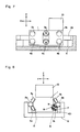
- Figs. 1 though 4 show a conventional carriage device for a disc memory storage apparatus as described in Japanese patent application No. 55-116673, wherein an optical read/write data transducer 10 for a memory disk (not shown) is mounted to a carriage 1 slidable on a pair of parallel guide rods or rails 2a and 2b disposed at opposite sides A and B of the carriage.
- Two identical pairs of symmetrically arranged and longitudinally spaced bearing rollers or wheels 3a, 4a and 3b, 4b are mounted on side A of the carriage and ride on the guide rail 2a.
- a single pair of similar bearing rollers 3c and 4c is mounted on a metal spring plate 5 to the other side B of the carriage, and ride on the guide rail 2b.
- the guide rails are fixed on a base 6.
- a linear motor coil 11 (shown only in Fig. 1) is fixed to the carriage 1, and cooperates with magnetic core structures 12a and 12b disposed on opposite sides thereof.
- the present invention solves the above described problems, and provides a carriage mount with improved positioning accuracy by preventing any rotational movements of the carriage around the X, Y and Z axes and the attendant harmful vibrations, and with improved space saving and lightweighting.
- all of the bearing rollers are mounted directly on the carriage, with a lower roller of the intermediate pair (on the single pair side of the carriage) not carrying any of the carriage weight and instead being elastically mounted such that it exerts a force on the engaged guide rail to urge the carriage downwardly and laterally away from the guide rail.
- Such elastic urging in turn provides the necessary reactive biasing force, together with the weight of the carriage, to maintain the remaining bearing rollers in stable and continuous contact with their associated guide rails.
- Figs. 5 through 9 show a preferred embodiment of a carriage mount according to the present invention, wherein like reference numerals identify the same structural elements as shown and described in Figs. 1-4.
- the single pair of bearing rollers 3c and 4c on the B side of the carriage, disposed intermediate the two roller pairs on the A side, are mounted directly to the carriage and the spring plate 5 has been eliminated.
- the outer end of the shaft 7 is fixed to the inner ring or race 401 of bearing 4c which is disposed at the lower side on the guide rail 2b, free from the weight of the carriage 1.
- the inner end of the shaft 7 is fixed to an elastic member 9, such as a gum rubber ring.
- the elastic member 9 is fixedly inserted into an aperture 8 in the carriage, as seen in Figs. 8 and 9.
- the dimensions and parameters of the elastic member 9 are selected such that the roller 4c exerts a positive and predetermined force on the guide rail 2b, and the reactions to this force, together with the weight of the carriage, maintain the remaining rollers in stable and continuous engagement with their associated guide rails.
- the fixed or rigidly mounted bearing rollers 3a, 3b, 3c, 4a and 4b accurately establish the sliding position of the carriage on the guide rails, and the elastically or resilient mounted intermediate lower bearing roller 4c alone serves to stably maintain such established position. Vibrationally induced rotations or chatterings of the carriage about the X axis are thereby avoided, to attendantly improve the positioning accuracy of the transducer even when the carriage is subjected to rapid acceleration and deceleration.
- the direct mounting of all of the rollers to the carriage also results in a more dimensionally compact construction.
- the elastic mounting member 9 has been described as a gum rubber ring, it may alternatively comprise a metal spring member 9A as shown in Fig. 10.
- Fig. 11 shows a vertically oriented embodiment of the invention, wherein the elastically mounted bearing roller 4c is attached to an upper side of the carriage and is similarly free from the weight thereof.
Landscapes
- Moving Of Heads (AREA)
- Bearings For Parts Moving Linearly (AREA)
Applications Claiming Priority (2)
| Application Number | Priority Date | Filing Date | Title |
|---|---|---|---|
| JP166521/85 | 1985-07-27 | ||
| JP60166521A JPS6226676A (ja) | 1985-07-27 | 1985-07-27 | デイスク装置のキヤリツジ支持装置 |
Publications (2)
| Publication Number | Publication Date |
|---|---|
| EP0210781A1 true EP0210781A1 (fr) | 1987-02-04 |
| EP0210781B1 EP0210781B1 (fr) | 1991-11-21 |
Family
ID=15832857
Family Applications (1)
| Application Number | Title | Priority Date | Filing Date |
|---|---|---|---|
| EP86305418A Expired - Lifetime EP0210781B1 (fr) | 1985-07-27 | 1986-07-15 | Support de chariot coulissant pour appareil à disque de mémoire |
Country Status (5)
| Country | Link |
|---|---|
| US (1) | US4819109A (fr) |
| EP (1) | EP0210781B1 (fr) |
| JP (1) | JPS6226676A (fr) |
| CA (1) | CA1258905A (fr) |
| DE (1) | DE3682544D1 (fr) |
Cited By (2)
| Publication number | Priority date | Publication date | Assignee | Title |
|---|---|---|---|---|
| EP0190763A3 (en) * | 1985-02-08 | 1988-08-24 | Mitsubishi Denki Kabushiki Kaisha | Data converter pickup carriage assembly |
| EP0407215A3 (en) * | 1989-07-06 | 1991-05-02 | Matsushita Electric Industrial Co., Ltd. | Optical recording and reproducing apparatus |
Families Citing this family (4)
| Publication number | Priority date | Publication date | Assignee | Title |
|---|---|---|---|---|
| JPS6248250A (ja) * | 1985-08-24 | 1987-03-02 | Canon Inc | リニアモ−タの直線運動案内装置 |
| US5124971A (en) * | 1988-07-12 | 1992-06-23 | Nec Corporation | Optical head driving device |
| JPH0460929A (ja) * | 1990-06-25 | 1992-02-26 | Canon Inc | 光学ヘッド及び該光学ヘッドを備えた光学的情報記録再生装置 |
| US5428583A (en) * | 1991-10-31 | 1995-06-27 | Sony Corporation | Magneto-optical disc recording/reproducing apparatus |
Citations (4)
| Publication number | Priority date | Publication date | Assignee | Title |
|---|---|---|---|---|
| US4006372A (en) * | 1975-03-10 | 1977-02-01 | Wangco Incorporated | Transducer positioner |
| US4068268A (en) * | 1976-01-08 | 1978-01-10 | Idemoto Tom Y | Method and apparatus for writing servo-tracks on rotating magnetic memory surfaces |
| US4393425A (en) * | 1981-03-30 | 1983-07-12 | Disctron, Inc. | Linear head actuator |
| EP0160447A2 (fr) * | 1984-04-25 | 1985-11-06 | Seagate Technology, Inc. | Actuateur linéaire pour entraînement de disque |
Family Cites Families (7)
| Publication number | Priority date | Publication date | Assignee | Title |
|---|---|---|---|---|
| US3922720A (en) * | 1974-01-09 | 1975-11-25 | Information Storage Systems | Carriage assembly for a magnetic disc storage drive |
| US4044977A (en) * | 1976-04-16 | 1977-08-30 | Caterpillar Tractor Co. | Bushing type mount with triple spring rate |
| DE2742050A1 (de) * | 1977-09-19 | 1979-03-29 | Papst Motoren Kg | Mehrphasen-linearmotor |
| JPS55116673A (en) * | 1979-02-27 | 1980-09-08 | Tokyo Shibaura Electric Co | Hot press method for silicon nitride body |
| JPS5740785A (en) * | 1980-08-25 | 1982-03-06 | Fujitsu Ltd | Carriage support mechanism of magnetic disk device |
| JPS61267972A (ja) * | 1985-05-22 | 1986-11-27 | Hitachi Ltd | キヤリツジの支持構造 |
| US4730226A (en) * | 1986-01-06 | 1988-03-08 | Unisys Corporation | Actuator carriage with "splayed-bearing" array |
-
1985
- 1985-07-27 JP JP60166521A patent/JPS6226676A/ja active Pending
-
1986
- 1986-06-09 US US06/872,373 patent/US4819109A/en not_active Expired - Fee Related
- 1986-07-11 CA CA000513622A patent/CA1258905A/fr not_active Expired
- 1986-07-15 EP EP86305418A patent/EP0210781B1/fr not_active Expired - Lifetime
- 1986-07-15 DE DE8686305418T patent/DE3682544D1/de not_active Expired - Lifetime
Patent Citations (4)
| Publication number | Priority date | Publication date | Assignee | Title |
|---|---|---|---|---|
| US4006372A (en) * | 1975-03-10 | 1977-02-01 | Wangco Incorporated | Transducer positioner |
| US4068268A (en) * | 1976-01-08 | 1978-01-10 | Idemoto Tom Y | Method and apparatus for writing servo-tracks on rotating magnetic memory surfaces |
| US4393425A (en) * | 1981-03-30 | 1983-07-12 | Disctron, Inc. | Linear head actuator |
| EP0160447A2 (fr) * | 1984-04-25 | 1985-11-06 | Seagate Technology, Inc. | Actuateur linéaire pour entraînement de disque |
Cited By (3)
| Publication number | Priority date | Publication date | Assignee | Title |
|---|---|---|---|---|
| EP0190763A3 (en) * | 1985-02-08 | 1988-08-24 | Mitsubishi Denki Kabushiki Kaisha | Data converter pickup carriage assembly |
| EP0407215A3 (en) * | 1989-07-06 | 1991-05-02 | Matsushita Electric Industrial Co., Ltd. | Optical recording and reproducing apparatus |
| US5130972A (en) * | 1989-07-06 | 1992-07-14 | Matsushita Electric Industrial Co., Ltd. | Optical recording and reproducing apparatus |
Also Published As
| Publication number | Publication date |
|---|---|
| JPS6226676A (ja) | 1987-02-04 |
| DE3682544D1 (de) | 1992-01-02 |
| EP0210781B1 (fr) | 1991-11-21 |
| CA1258905A (fr) | 1989-08-29 |
| US4819109A (en) | 1989-04-04 |
Similar Documents
| Publication | Publication Date | Title |
|---|---|---|
| EP0750305A1 (fr) | Moteur d'axe à rotor extérieur | |
| EP0210781A1 (fr) | Support de chariot coulissant pour appareil à disque de mémoire | |
| US4678951A (en) | Linear motor | |
| JPS6211429B2 (fr) | ||
| US5012372A (en) | Head access mechanism for moving heads | |
| JPS61269267A (ja) | デイスク装置のキヤリツジ支持装置 | |
| EP0967597B1 (fr) | Montage avec chariot de tête magnétique et actionneur | |
| US4568992A (en) | Disc drive linear actuator | |
| JPS61280037A (ja) | 光学ピツクアツプ駆動装置 | |
| US5105419A (en) | Carriage assembly | |
| JP2826465B2 (ja) | リニアパルスモータの可動子案内機構 | |
| JPH0312053Y2 (fr) | ||
| JP2738671B2 (ja) | 磁気デイスク装置のリニアガイド機構 | |
| JPH07296575A (ja) | 移動体支持機構 | |
| JPS6215901Y2 (fr) | ||
| JPH021741Y2 (fr) | ||
| JPH01113967A (ja) | フロッピーディスクのヘッド・キャリッジ装置 | |
| JPH0752555B2 (ja) | 光学式情報記録再生装置 | |
| JPS61206931A (ja) | 光学式情報記録再生装置 | |
| JPS60162470A (ja) | リニアモ−タ装置 | |
| JPS61117773A (ja) | 磁気記憶装置 | |
| JPH09184517A (ja) | リニアモータ付xyテーブル | |
| JPH03112355A (ja) | キャリッジ駆動装置 | |
| JPH0727195A (ja) | 滑り軸受案内機構 | |
| JPH07130109A (ja) | 往復移動体の支持機構 |
Legal Events
| Date | Code | Title | Description |
|---|---|---|---|
| PUAI | Public reference made under article 153(3) epc to a published international application that has entered the european phase |
Free format text: ORIGINAL CODE: 0009012 |
|
| AK | Designated contracting states |
Kind code of ref document: A1 Designated state(s): DE FR GB |
|
| 17P | Request for examination filed |
Effective date: 19870331 |
|
| 17Q | First examination report despatched |
Effective date: 19890127 |
|
| GRAA | (expected) grant |
Free format text: ORIGINAL CODE: 0009210 |
|
| AK | Designated contracting states |
Kind code of ref document: B1 Designated state(s): DE FR GB |
|
| REF | Corresponds to: |
Ref document number: 3682544 Country of ref document: DE Date of ref document: 19920102 |
|
| ET | Fr: translation filed | ||
| PGFP | Annual fee paid to national office [announced via postgrant information from national office to epo] |
Ref country code: GB Payment date: 19920630 Year of fee payment: 7 |
|
| PGFP | Annual fee paid to national office [announced via postgrant information from national office to epo] |
Ref country code: FR Payment date: 19920707 Year of fee payment: 7 |
|
| PGFP | Annual fee paid to national office [announced via postgrant information from national office to epo] |
Ref country code: DE Payment date: 19920727 Year of fee payment: 7 |
|
| PLBE | No opposition filed within time limit |
Free format text: ORIGINAL CODE: 0009261 |
|
| STAA | Information on the status of an ep patent application or granted ep patent |
Free format text: STATUS: NO OPPOSITION FILED WITHIN TIME LIMIT |
|
| 26N | No opposition filed | ||
| PG25 | Lapsed in a contracting state [announced via postgrant information from national office to epo] |
Ref country code: GB Effective date: 19930715 |
|
| GBPC | Gb: european patent ceased through non-payment of renewal fee |
Effective date: 19930715 |
|
| PG25 | Lapsed in a contracting state [announced via postgrant information from national office to epo] |
Ref country code: FR Effective date: 19940331 |
|
| PG25 | Lapsed in a contracting state [announced via postgrant information from national office to epo] |
Ref country code: DE Effective date: 19940401 |
|
| REG | Reference to a national code |
Ref country code: FR Ref legal event code: ST |