EP0210823B1 - Dispositif et procédé de laminage pour emballage "blister" - Google Patents
Dispositif et procédé de laminage pour emballage "blister" Download PDFInfo
- Publication number
- EP0210823B1 EP0210823B1 EP86305621A EP86305621A EP0210823B1 EP 0210823 B1 EP0210823 B1 EP 0210823B1 EP 86305621 A EP86305621 A EP 86305621A EP 86305621 A EP86305621 A EP 86305621A EP 0210823 B1 EP0210823 B1 EP 0210823B1
- Authority
- EP
- European Patent Office
- Prior art keywords
- blister pack
- barrier film
- during
- film
- further characterized
- Prior art date
- Legal status (The legal status is an assumption and is not a legal conclusion. Google has not performed a legal analysis and makes no representation as to the accuracy of the status listed.)
- Expired
Links
- 238000010030 laminating Methods 0.000 title claims description 30
- 238000000034 method Methods 0.000 title claims description 25
- 230000004888 barrier function Effects 0.000 claims description 63
- 238000005520 cutting process Methods 0.000 claims description 9
- 239000004820 Pressure-sensitive adhesive Substances 0.000 claims description 6
- 230000000977 initiatory effect Effects 0.000 claims description 2
- 230000002265 prevention Effects 0.000 claims 3
- 238000003825 pressing Methods 0.000 claims 2
- 230000001351 cycling effect Effects 0.000 description 7
- 239000000853 adhesive Substances 0.000 description 6
- 230000001070 adhesive effect Effects 0.000 description 6
- 238000004806 packaging method and process Methods 0.000 description 6
- 239000003814 drug Substances 0.000 description 3
- 229940079593 drug Drugs 0.000 description 3
- 229920001577 copolymer Polymers 0.000 description 2
- 239000000463 material Substances 0.000 description 2
- 239000006187 pill Substances 0.000 description 2
- 230000000717 retained effect Effects 0.000 description 2
- 238000007789 sealing Methods 0.000 description 2
- 238000013459 approach Methods 0.000 description 1
- 239000011248 coating agent Substances 0.000 description 1
- 238000000576 coating method Methods 0.000 description 1
- 238000010276 construction Methods 0.000 description 1
- 238000006073 displacement reaction Methods 0.000 description 1
- 230000000694 effects Effects 0.000 description 1
- 238000003475 lamination Methods 0.000 description 1
- 238000004519 manufacturing process Methods 0.000 description 1
- 239000011101 paper laminate Substances 0.000 description 1
- 238000004080 punching Methods 0.000 description 1
- 125000000391 vinyl group Chemical group [H]C([*])=C([H])[H] 0.000 description 1
- 229920002554 vinyl polymer Polymers 0.000 description 1
Images



Classifications
-
- B—PERFORMING OPERATIONS; TRANSPORTING
- B65—CONVEYING; PACKING; STORING; HANDLING THIN OR FILAMENTARY MATERIAL
- B65B—MACHINES, APPARATUS OR DEVICES FOR, OR METHODS OF, PACKAGING ARTICLES OR MATERIALS; UNPACKING
- B65B7/00—Closing containers or receptacles after filling
- B65B7/16—Closing semi-rigid or rigid containers or receptacles not deformed by, or not taking-up shape of, contents, e.g. boxes or cartons
- B65B7/162—Closing semi-rigid or rigid containers or receptacles not deformed by, or not taking-up shape of, contents, e.g. boxes or cartons by feeding web material to securing means
-
- F—MECHANICAL ENGINEERING; LIGHTING; HEATING; WEAPONS; BLASTING
- F02—COMBUSTION ENGINES; HOT-GAS OR COMBUSTION-PRODUCT ENGINE PLANTS
- F02B—INTERNAL-COMBUSTION PISTON ENGINES; COMBUSTION ENGINES IN GENERAL
- F02B75/00—Other engines
- F02B75/02—Engines characterised by their cycles, e.g. six-stroke
- F02B2075/022—Engines characterised by their cycles, e.g. six-stroke having less than six strokes per cycle
- F02B2075/025—Engines characterised by their cycles, e.g. six-stroke having less than six strokes per cycle two
-
- Y—GENERAL TAGGING OF NEW TECHNOLOGICAL DEVELOPMENTS; GENERAL TAGGING OF CROSS-SECTIONAL TECHNOLOGIES SPANNING OVER SEVERAL SECTIONS OF THE IPC; TECHNICAL SUBJECTS COVERED BY FORMER USPC CROSS-REFERENCE ART COLLECTIONS [XRACs] AND DIGESTS
- Y10—TECHNICAL SUBJECTS COVERED BY FORMER USPC
- Y10T—TECHNICAL SUBJECTS COVERED BY FORMER US CLASSIFICATION
- Y10T156/00—Adhesive bonding and miscellaneous chemical manufacture
- Y10T156/12—Surface bonding means and/or assembly means with cutting, punching, piercing, severing or tearing
- Y10T156/1317—Means feeding plural workpieces to be joined
- Y10T156/1343—Cutting indefinite length web after assembly with discrete article
Definitions
- the present invention relates to a laminating device and method, and more particularly, a laminating device and method for laminating a one sided pressure sensitive adhesive coated barrier film to a blister pack and cutting the laminated barrier film.
- US-A-4002009 is regarded as the nearest prior art in that it discloses a hand operated device for laminating an adhesive coated barrier film to blister packs.
- the blister pack is placed in a tray and fed through a housing containing roller means for laminating a single sided pressure sensitive adhesive barrier film to the blister pack.
- the blister pack is manually lifted out of the tray, during which step the trailing end of the barrier film, that has been supplied from a roll thereof, is manually severed by a knife forming part of the device.
- EP-A-0110241 discloses a device for laminating a barrier film to a blister pack comprising a housing, a tray for holding a blister pack and barrier film applicator means.
- a two cycle carriage assembly for movement in said housing the carriage moving into said housing during one cycle and out of said housing during one cycle.
- the tray means hold the blister pack on the carriage assembly and the barrier film applicator means laminates the barrier film to the blister pack when it has been moved into the housing.
- the carriage assembly comprises tray means formed integrally with the carriage. Heat sealing is used to secure the barrier film to the blister pack.
- the present invention provides a novel blister pack laminating device and method for laminating a one sided pressure sensitive adhesive coated barrier film to a preformed blister pack, as specified in Claims 1 and 12.
- An important feature of the device and method is to provide pressure through the film and blister pack against preselected pressure or bonding areas associated with the tray sufficient to bond the barrier film to the blister pack.
- An additional feature includes a pair of rollers connected to the barrier film applicator whereby the pressure is applied by at least one of the rollers as the film is applied to the blister pack.
- a further feature of the invention includes preventing the barrier film from contacting the blister pack during one of the cycles, whereby the barrier film is held between the rollers and is backed away from the blister pack, and applying the barrier film to the blister pack during the other cycle, whereby the pair of rollers advance the film toward and in contact with the blister pack to apply it.
- the backward rotation of the rollers is stopped by means of a pair of cams so that the barrier film is only backed away from the blister pack a predetermined amount so that the film remains between the rollers, and the cams are adapted for initiating the rotation of the rollers during the other cycle to apply the film to the blister pack.
- the tray is releasably retained on the carriage assembly and includes a grate having bonding or pressure areas associated therewith.
- a grate having bonding or pressure areas associated therewith.
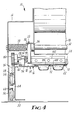
- the blister pack laminating device of the present invention comprises a housing 12, a two-cycle carriage assembly 14, a tray 16, a roll of barrier film 18, and a barrier film applicator generally designated 20 for laminating the barrier film to blister pack 22 during cycling.
- Applicator assembly 20 includes a pair of rollers consisting of an applying roller 24 and a nip roller 26 (FIGS. 3 and 4).
- Applying roller 24 has a support shaft 28 running along the longitudinal axis of the roller to allow free rotation of the roller during cycling.
- a support arm 30 attaches shaft 28 and roller 24 to a central support shaft 32.
- the nip roller 26 has a support shaft 34 running along the longitudinal axis of the roller to allow free rotation of the roller during cycling.
- An arm 36 attaches roller 26 to the central shaft 32.
- a pair of torsion springs 38 on the shaft 32 bias the arms 36 and roller 26 into frictional counter clockwise engagement with roller 24.
- Carriage assembly 14 includes a bed 40 moveably supported within housing 12 for reciprocatory, linear movement into the housing during one cycle and out of the housing during one cycle.
- Bed 40 includes a top 42, sides 44, front 46, back 48 and bottom 50 (FIGS. 2 and 3).
- Bed 40 is supported within housing 12 by two sets of rollers 54 and 56 (FIGS. 2 and 4).
- Rollers 54 are connected to housing 12 opposite bed sides 44, and engage a track 58 affixed along each side 44 of the bed 40.
- additional tracks 60 are attached to housing 12 opposite bed sides 44, and rollers 56 are attached to bed sides 44 near back 48 of the bed 40 and are engageable with track 60.
- a handle 52 attached to bed front 46 enables the user to grasp it with one hand to reciprocate carriage assembly 14 in and out of the housing.
- Stops 64 are attached to the housing 12 and are engageable with the outside surface of bed back 48 to terminate linear movement of bed 40 when it is cycled into the housing (FIGS. 2 and 3).
- stops 66 are attached to housing 12, and are engageable with the inside surface of bed back 48 to stop linear movement of bed 40 when it is cycled out of the housing.
- Tray 16 includes a preselected grate 70 having pressure or bonding areas 72 associated with the top surface thereof (FIG. 1 and 4). Areas 72 correspond to the desired laminating areas of the preselected blister pack 22. Tray 16 may be releasably retained on bed top 42 by a suitable retaining means so that different grate configurations may be utilized for laminating different blister packs.
- the particular retaining means 43 should not interfere with or project past the surface of tray 16.
- the particular means is not essential to the present invention, but, for example, a particular means might include flat head screws at each corner of the tray 16 or a detent means which will provide ease of use and changeability.
- barrier film 18 and the material forming the blister pack 22 are not essential to the invention herein, except the adhesive coating on the film and the blister pack material have to be compatible, and be pressure sensitive at room temperature.
- the barrier film 18 is a foil-paper-backed tape having an adhesive copolymer layer which cooperates with a vinyl blister pack, which has been found to be preferred for laminating multi-compartment blister packs in accordance with the device and method of the present invention.
- the adhesive copolymer layer is substantially non- tacky it does not become strongly bonded to, for example, pills or other forms of medication which can then be easily removed from each blister pack compartment by punching them out the foil-paper laminate.
- film 18 is advanced from spool 74 and the film backing is removed from the film and wound upon spool 76 to be discarded when the roll of film 18 is replaced.
- a gear 80 is attached to the end of applying roller shaft 28, and gear 80 is engageable with rack 82 which runs along the top 42 of carriage bed 40, whereby during inward and outward cycling of the carriage assembly, rollers 24 and 26 rotate to advance or retract a portion 84 of barrier film 18 positioned between the rollers (FIGS. 3 and 4).
- at least one of the applicator assembly rollers 24 or 26 is engageably biased towards grate 70 by springs 38 to apply pressure through the barrier film and blister pack against the grate at bonding areas 72 during cycling.
- a pair of cams 92 are attached to the ends of shaft 28 which engage and ride along surfaces 94 of bed top 42 (FIGS. 3 and 4).
- a pair of upwardly sloping ramps 96 are provided along track surface 94 to prevent film 18 from being applied during one of the cycles.
- An additional downwardly sloping pair of ramps 98 are provided at the ends of track surface 94 to lower the pair of rollers in pressure contact with blister pack 22 and to lower gear 80 in engagement with rack 82.
- rollers 24 and 26 advance film 18 into contact with blister pack 22 to apply it (FIG. 3).
- a pair of torsion springs 99 bias cams 92 in engagement with cam follower track surface 94 during only one cycle and permit cams 92 to be collapsed out of riding contact with surface 94 during the other cycle. It is contemplated that ramps 96 and 98 be adjustable to change the amount of film 18 applied to the particular blister pack when necessary.
- a cutting blade 100 is positioned near the pair of rollers 24 and 26, whereby after laminating film 18 to blister pack 22 the film can be cut (FIG. 4). Cutting blade 100 is fastened to bar 102 and the bar is supported between support arms 30.
- a preselected blister pack 22 is placed on tray grate 70.
- Grate 70 and blister pack 22 each have, associated therewith, the desired pressure or bonding areas 72 corresponding to the preselected blister pack.
- the user grasps handle 52 with at least one hand and cycles carriage assembly 14 into housing 12.
- cams 92 engage upwardly inclined ramp surfaces 96 lifting rollers 24 and 26 out of pressure contact with blister pack 22, and gear 80 is disengaged from rotational contact with rack 82 after the rollers have retracted a predetermined portion 84 of the film.
- cams 92 descend down ramp surface 98 to allow rollers 24 and 26 to come in pressure contact with blister pack 22, and gear 80 to come in rotational contact with rack 82 to position the rollers 24 and 26 to apply the film 18 (FIG. 5).
- carriage assembly 14 is cycled out of housing 12 during which cams 92 collapse out of their riding position so that one of the rollers 24 or 26 remains in pressure contact with blister pack 22, and film 18 is advanced in contact with and applied to the blister pack while at least one of the rollers 24 or 26 apply pressure through film 18 and blister pack 22 against pressure or bonding areas 72 (FIG. 6).
- cams 92 will ride down ramp surfaces 96 to attain their initial riding positions (FIG. 7).
- the present laminating device and method described herein can be useful for making medication cards having one punch-open compartments per pill.
- the device and method may be utilized in laminating a multitude of blister packs having compartments for containing various items, for example, hardware items, sporting good items, or the like.
Landscapes
- Engineering & Computer Science (AREA)
- Mechanical Engineering (AREA)
- Packages (AREA)
- Containers And Plastic Fillers For Packaging (AREA)
- Closing Of Containers (AREA)
Claims (18)
Applications Claiming Priority (2)
| Application Number | Priority Date | Filing Date | Title |
|---|---|---|---|
| US758530 | 1985-07-24 | ||
| US06/758,530 US4612755A (en) | 1985-07-24 | 1985-07-24 | Blister pack laminating device and method |
Publications (2)
| Publication Number | Publication Date |
|---|---|
| EP0210823A1 EP0210823A1 (fr) | 1987-02-04 |
| EP0210823B1 true EP0210823B1 (fr) | 1989-09-20 |
Family
ID=25052069
Family Applications (1)
| Application Number | Title | Priority Date | Filing Date |
|---|---|---|---|
| EP86305621A Expired EP0210823B1 (fr) | 1985-07-24 | 1986-07-22 | Dispositif et procédé de laminage pour emballage "blister" |
Country Status (5)
| Country | Link |
|---|---|
| US (1) | US4612755A (fr) |
| EP (1) | EP0210823B1 (fr) |
| JP (1) | JPS6228309A (fr) |
| CA (1) | CA1302861C (fr) |
| DE (1) | DE3665697D1 (fr) |
Families Citing this family (13)
| Publication number | Priority date | Publication date | Assignee | Title |
|---|---|---|---|---|
| US4776150A (en) * | 1986-12-31 | 1988-10-11 | Siegel Harold B | Sealing apparatus |
| US4848066A (en) * | 1988-04-21 | 1989-07-18 | Minnesota Mining And Manufacturing Company | Method and apparatus for assembling blister packages |
| JPH08564B2 (ja) * | 1989-08-31 | 1996-01-10 | 株式会社松澤製作所 | 熱可塑性樹脂シートのシール方法及び装置 |
| US5252166A (en) * | 1990-07-09 | 1993-10-12 | Krawczyk Margaret M | Packaging arrangements for items to be subsequently mounted |
| US5622028A (en) * | 1995-07-25 | 1997-04-22 | Harp; Ralph E. | Pharmaceutical unit dose package sealing apparatus and method |
| US6408595B1 (en) | 1999-11-02 | 2002-06-25 | Union Scientific Corporation | Microplate cover seal applicator |
| US20050284789A1 (en) * | 2004-06-29 | 2005-12-29 | Carespodi Dennis L | Laser-scored push-through blister backing and methods of making same |
| DE102004062864A1 (de) * | 2004-12-21 | 2006-06-22 | Boehringer Ingelheim Pharma Gmbh & Co. Kg | Folienbehälter |
| GB2433887A (en) * | 2006-01-04 | 2007-07-11 | Reckitt Benckiser Healthcare | Pack for phenothiazine derivatives |
| GB2441754B (en) * | 2006-09-16 | 2011-07-27 | Nobac Ltd | Packaging machine |
| EP3135602A1 (fr) | 2015-08-25 | 2017-03-01 | Bayer Pharma Aktiengesellschaft | Blister |
| AU2017303402A1 (en) | 2016-07-26 | 2019-02-21 | Bayer Aktiengesellschaft | Exact joining of films |
| EP4529983A1 (fr) * | 2023-09-29 | 2025-04-02 | Roche Diagnostics International AG | Dispositif et procédé de fermeture d'un récipient d'échantillon |
Citations (1)
| Publication number | Priority date | Publication date | Assignee | Title |
|---|---|---|---|---|
| EP0110241A1 (fr) * | 1982-11-25 | 1984-06-13 | Aldo Artusi | Dispositif de scellement d'une feuille ou similaire sur un récipient |
Family Cites Families (6)
| Publication number | Priority date | Publication date | Assignee | Title |
|---|---|---|---|---|
| US3378991A (en) * | 1965-08-30 | 1968-04-23 | Ralph F. Anderson | Heat sealing apparatus |
| US3693318A (en) * | 1970-08-26 | 1972-09-26 | Winton E Balzer | Tray covering and sealing apparatus |
| US3792567A (en) * | 1971-12-07 | 1974-02-19 | Dixie Packaging Co Inc | Heat sealing machine |
| US3856144A (en) * | 1973-01-15 | 1974-12-24 | F Kelly | Blister packaging assembly |
| US4002009A (en) * | 1975-08-21 | 1977-01-11 | Dynatech Laboratories, Incorporated | Combination tape dispenser and tray sealer device |
| JPS573601U (fr) * | 1980-06-09 | 1982-01-09 |
-
1985
- 1985-07-24 US US06/758,530 patent/US4612755A/en not_active Expired - Fee Related
-
1986
- 1986-06-16 CA CA000511641A patent/CA1302861C/fr not_active Expired - Lifetime
- 1986-07-22 DE DE8686305621T patent/DE3665697D1/de not_active Expired
- 1986-07-22 EP EP86305621A patent/EP0210823B1/fr not_active Expired
- 1986-07-23 JP JP61171973A patent/JPS6228309A/ja active Pending
Patent Citations (1)
| Publication number | Priority date | Publication date | Assignee | Title |
|---|---|---|---|---|
| EP0110241A1 (fr) * | 1982-11-25 | 1984-06-13 | Aldo Artusi | Dispositif de scellement d'une feuille ou similaire sur un récipient |
Also Published As
| Publication number | Publication date |
|---|---|
| CA1302861C (fr) | 1992-06-09 |
| DE3665697D1 (en) | 1989-10-26 |
| JPS6228309A (ja) | 1987-02-06 |
| EP0210823A1 (fr) | 1987-02-04 |
| US4612755A (en) | 1986-09-23 |
Similar Documents
| Publication | Publication Date | Title |
|---|---|---|
| EP0210823B1 (fr) | Dispositif et procédé de laminage pour emballage "blister" | |
| US4293369A (en) | Machine for the application of suction tubes to packing containers | |
| JPH044210B2 (fr) | ||
| SE454681B (sv) | Anordning for applicering av foremal pa forpackningsbehallare | |
| CN106743948B (zh) | 一种胶带使用工具 | |
| US5875614A (en) | Apparatus and methods for forming flexible packaging containers for discs | |
| CN112340518A (zh) | 一种桌面式标签打印覆膜裁切一体机 | |
| US4149484A (en) | Cutting apparatus | |
| JP3653337B2 (ja) | テープ巻取装置 | |
| JP3611328B2 (ja) | 小冊子の製造方法および製造装置 | |
| US4786355A (en) | Label application apparatus | |
| US4002003A (en) | Method for securing articles to a display board | |
| US4743153A (en) | Method and apparatus for stacking articles | |
| US20030234084A1 (en) | Set-down box | |
| US3885373A (en) | Apparatus for securing articles to a display board | |
| CN108382644B (zh) | 一种产品半包装装置 | |
| JPH05503470A (ja) | 小冊子を作製する方法および装置 | |
| JPS587530B2 (ja) | 箱体の封緘機 | |
| CN218699068U (zh) | 一种新型包装印刷裁剪装置 | |
| CN218026546U (zh) | 一种整经机用托架纸条存储装置 | |
| US3471918A (en) | Machine for placement,cutting,fastening transparent plastic windows in cover rings | |
| JPH0110335Y2 (fr) | ||
| CN213057803U (zh) | 一种包装袋热封切割装置 | |
| JPS643733B2 (fr) | ||
| JPS5852144A (ja) | スタツクのシ−トをそろえる方法と装置 |
Legal Events
| Date | Code | Title | Description |
|---|---|---|---|
| PUAI | Public reference made under article 153(3) epc to a published international application that has entered the european phase |
Free format text: ORIGINAL CODE: 0009012 |
|
| AK | Designated contracting states |
Kind code of ref document: A1 Designated state(s): DE FR GB IT |
|
| 17P | Request for examination filed |
Effective date: 19870803 |
|
| 17Q | First examination report despatched |
Effective date: 19880509 |
|
| ITF | It: translation for a ep patent filed | ||
| GRAA | (expected) grant |
Free format text: ORIGINAL CODE: 0009210 |
|
| AK | Designated contracting states |
Kind code of ref document: B1 Designated state(s): DE FR GB IT |
|
| REF | Corresponds to: |
Ref document number: 3665697 Country of ref document: DE Date of ref document: 19891026 |
|
| ET | Fr: translation filed | ||
| PLBE | No opposition filed within time limit |
Free format text: ORIGINAL CODE: 0009261 |
|
| STAA | Information on the status of an ep patent application or granted ep patent |
Free format text: STATUS: NO OPPOSITION FILED WITHIN TIME LIMIT |
|
| 26N | No opposition filed | ||
| ITTA | It: last paid annual fee | ||
| PGFP | Annual fee paid to national office [announced via postgrant information from national office to epo] |
Ref country code: FR Payment date: 19940613 Year of fee payment: 9 |
|
| PGFP | Annual fee paid to national office [announced via postgrant information from national office to epo] |
Ref country code: GB Payment date: 19940620 Year of fee payment: 9 |
|
| PGFP | Annual fee paid to national office [announced via postgrant information from national office to epo] |
Ref country code: DE Payment date: 19940623 Year of fee payment: 9 |
|
| PG25 | Lapsed in a contracting state [announced via postgrant information from national office to epo] |
Ref country code: GB Effective date: 19950722 |
|
| GBPC | Gb: european patent ceased through non-payment of renewal fee |
Effective date: 19950722 |
|
| PG25 | Lapsed in a contracting state [announced via postgrant information from national office to epo] |
Ref country code: DE Effective date: 19960402 |
|
| PG25 | Lapsed in a contracting state [announced via postgrant information from national office to epo] |
Ref country code: FR Effective date: 19960430 |
|
| REG | Reference to a national code |
Ref country code: FR Ref legal event code: ST |
|
| REG | Reference to a national code |
Ref country code: FR Ref legal event code: ST |
|
| REG | Reference to a national code |
Ref country code: FR Ref legal event code: ST |
|
| PG25 | Lapsed in a contracting state [announced via postgrant information from national office to epo] |
Ref country code: IT Free format text: LAPSE BECAUSE OF NON-PAYMENT OF DUE FEES;WARNING: LAPSES OF ITALIAN PATENTS WITH EFFECTIVE DATE BEFORE 2007 MAY HAVE OCCURRED AT ANY TIME BEFORE 2007. THE CORRECT EFFECTIVE DATE MAY BE DIFFERENT FROM THE ONE RECORDED. Effective date: 20050722 |