EP0210940A1 - Ruban d'étanchéité en forme d'échelle avec des brides latérales - Google Patents
Ruban d'étanchéité en forme d'échelle avec des brides latérales Download PDFInfo
- Publication number
- EP0210940A1 EP0210940A1 EP86630095A EP86630095A EP0210940A1 EP 0210940 A1 EP0210940 A1 EP 0210940A1 EP 86630095 A EP86630095 A EP 86630095A EP 86630095 A EP86630095 A EP 86630095A EP 0210940 A1 EP0210940 A1 EP 0210940A1
- Authority
- EP
- European Patent Office
- Prior art keywords
- seal
- slot
- blade
- extending
- axially
- Prior art date
- Legal status (The legal status is an assumption and is not a legal conclusion. Google has not performed a legal analysis and makes no representation as to the accuracy of the status listed.)
- Granted
Links
- 239000007789 gas Substances 0.000 abstract description 21
- 238000007789 sealing Methods 0.000 abstract description 5
- 238000003754 machining Methods 0.000 description 3
- 230000006835 compression Effects 0.000 description 2
- 238000007906 compression Methods 0.000 description 2
- 230000000717 retained effect Effects 0.000 description 2
- 230000000712 assembly Effects 0.000 description 1
- 238000000429 assembly Methods 0.000 description 1
- 238000002485 combustion reaction Methods 0.000 description 1
- 230000007423 decrease Effects 0.000 description 1
- 230000003068 static effect Effects 0.000 description 1
Images


Classifications
-
- F—MECHANICAL ENGINEERING; LIGHTING; HEATING; WEAPONS; BLASTING
- F01—MACHINES OR ENGINES IN GENERAL; ENGINE PLANTS IN GENERAL; STEAM ENGINES
- F01D—NON-POSITIVE DISPLACEMENT MACHINES OR ENGINES, e.g. STEAM TURBINES
- F01D5/00—Blades; Blade-carrying members; Heating, heat-insulating, cooling or antivibration means on the blades or the members
- F01D5/30—Fixing blades to rotors; Blade roots ; Blade spacers
- F01D5/3023—Fixing blades to rotors; Blade roots ; Blade spacers of radial insertion type, e.g. in individual recesses
- F01D5/303—Fixing blades to rotors; Blade roots ; Blade spacers of radial insertion type, e.g. in individual recesses in a circumferential slot
- F01D5/3038—Fixing blades to rotors; Blade roots ; Blade spacers of radial insertion type, e.g. in individual recesses in a circumferential slot the slot having inwardly directed abutment faces on both sides
-
- F—MECHANICAL ENGINEERING; LIGHTING; HEATING; WEAPONS; BLASTING
- F01—MACHINES OR ENGINES IN GENERAL; ENGINE PLANTS IN GENERAL; STEAM ENGINES
- F01D—NON-POSITIVE DISPLACEMENT MACHINES OR ENGINES, e.g. STEAM TURBINES
- F01D11/00—Preventing or minimising internal leakage of working-fluid, e.g. between stages
- F01D11/005—Sealing means between non relatively rotating elements
- F01D11/006—Sealing the gap between rotor blades or blades and rotor
- F01D11/008—Sealing the gap between rotor blades or blades and rotor by spacer elements between the blades, e.g. independent interblade platforms
Definitions
- the present invention relates to gas turbine engines, and in particular, to blade root seals for rotor assemblies.
- a gas turbine engine has a compression section, a combustion section, and a turbine section.
- the compression and turbine sections have at least one rotor stage.
- Each rotor stage includes a disk which rotates about the axis of the engine, and a circumferential row of rotor blades extending radially outwardly from the disk into a flow path of working medium gases.
- Each blade has a platform which provides a boundary to the flow path. Radially inward of the platform is a blade root which engages a blade retaining slot in the disk.. In some rotor designs, the slot extends circumferentially about the rim of the disk.
- the platforms of adjacent blades are circumferentially spaced from each other, and working medium gases can leak from the flow path, through the gap between adjacent platforms, and then through the blade retaining slot. Also, the platforms are radially spaced from the disk rim, and the gases can leak under each platform, and through the blade slot. Such leakage of gases, from a region of high pressure to a region of low pressure, is undesireable, as it decreases the operating efficiency of the engine.
- the axial width of the seal is equal to the axial width of each blade platform, and each of the crossbars is in overlapping relation to the gap between adjacent blade platforms.
- centrifugal forces cause the seal to move radially outwardly into contact with the underside of the platforms to seal the gap and limit interplatform leakage of gases.
- the ladder seal has crossbars which, in the as-fabricated condition, are bowed radially inwardly. When the engine is at rest, the axial width of the seal is less than the distance between the recess sidewalls. During engine operation, the seal is forced radially outwardly into contact with the underside of the blade platforms.
- An object of the present invention is to increase the operating efficiency of a gas turbine engine.
- Another object of the present invention is an improved seal for limiting the leakage of working medium gases through the blade attachment area of a rotor disk.
- Yet another object of the present invention is a blade root platform seal which is easily installed in the rotor.
- an annular ladder seal comprising a plurality of circumferentially spaced apart crossbars integral with a pair of circumferentially extending, axially spaced apart strips, is disposed between the blade platforms and a circumferential blade retaining slot of a rotor disk, wherein the slot includes a recess having opposed, axially facing sidewalls, and each seal strip has a circumferential, radially inwardly extending flange axially adjacent to one of the sidewalls, and wherein the blade platforms are circumferentially spaced from each other, and radially spaced from the disk rim, the underside surface of each platform being inclined radially outwardly in opposite axial directions away from the blade root such that durinq engine operation, centrifugal forces bend the crossbars into sealinq relation with the underside surface of adjacent blade platforms to seal the gap between the platforms, and said forces move each seal flange radially outwardly into sealing relation with its respective sidewall surface to seal the gap between the platforms
- a primary advantage of the present invention is the increase in engine efficiency which results from the increased sealing effectiveness of the ladder seal.
- Another advantage of the present invention is that the radial clearance between the blade platform and the disk rim can be increased, since the flanges prevent leakage from the gas flow path and beneath the platforms during engine operation.
- the increase in allowable clearance simplifies machining of the disk and blades, since machining tolerances of both components can be relaxed. Also, the increased clearance allows for easier assembly of the seal to the rotor.
- An additional advantage of the present invention is that if any portion of the seal fractures during engine operation, the seal is retained within the blade slot by the flanges which contact the recess sidewalls, thus preventing foreign object damage to the engine components.
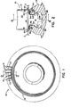
- a portion of a rotor assembly of a gas turbine engine as shown in Figs. 1 and 2, and generally represented by the reference numeral 10.
- the rotor assembly 10 includes a rotor disk 12 and a circumferential row of rotor blades 14 attached to the disk 12.
- the rotor assembly 10 rotates about an axis which is concentric with the engine axis.
- Each blade 14 includes a root 16, a platform 18 radially outward of the root 16, and an airfoil 20 radially outward of the platform 18.
- the root 16 engages a dove tail slot 22 in the disk 12, and has a lug 24 which contacts the base 26 of the slot 22, spacing the underside surface 34 of each platform 18 a minimum distance D from the disk rim 28.
- the platform underside surface 34 is inclined radially outwardly, in opposite axial directions, away from the blade root 16.
- one side of the platform surface 34 is inclined radially outwardly in the forward axial direction, and the other side is inclined radially outwardly in the rearward axial direction.
- each blade platform 18 has oppositely facing, axially extending and spaced apart ends 30, 32, Fig. 4.
- the ends 30, 32 of adjacent blades 14 are slightly spaced apart, and define a narrow gap G axially extending therebetween.
- the dove tail slot 22 extends circumferentially about the rim 28, and includes a circumferential seal retaining recess 40, Fig. 2.
- the recess 40 has axially opposed sidewalls 42, 44.
- Each blade platform 18 extends axially, in the forward and rearward directions, past the sidewalls 42, 44 of the seal recess 40.
- a flexible, annular seal 46 is disposed radially inwardly of the blade platforms 18, within the recess 40.
- the seal 46 has forward and rearward circumferentially extending, axially spaced apart strips 50, 52, respectively, and a plurality of circumferentially spaced apart crossbars 54 extending axially from the forward strip 50 to the rearward strip 52, and integral with both strips 50, 52.
- the opening 56 between adjacent crossbars 54 receives the root 16 of each blade 14, and one crossbar 54 overlies the gap G between adjacent blades 14, Fig. 4.
- the forward seal strip 50 is disposed axially adjacent to the recess forward sidewall 42
- the rearward seal strip 52 is disposed axially adjacent to the recess rearward sidewall 44.
- Each strip 50, 52 has a circumferential flange 58, 60, respectively, which extends radially inwardly therefrom, and which supports the seal upon a radially outwardly facing recess surface 48.
- each flange 58, 60 is slightly axially spaced from its respective recess sidewall 42, 44, and the seal 46 is radially spaced from the platform underside surface 34.
- the seal 46 limits the leakage of working medium gases which could move from the gas flow path, between the blade platforms 18 (through the axially extending gaps G) and through the blade retaining slot 22, as shown by the arrows 62 in Fig. 4.
- the seal 46 also limits the leakage of gases which could move beneath the blade platforms 18 (through the circumferentially extending gaps D) and through the blade retaining slot 22, as shown by the arrows 64 in Fig. 2.
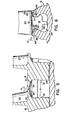
- each blade 14 and the seal 46 move radially outwardly in response to centrifugal forces, and the seal 46 comes to bear tightly against the underside surface 34 of each platform 18, Figs. 5-6.
- Figure 5 shows that each crossbar 54 bends into a V-shape, so as to conform to the shape of adjacent underside surfaces 34. Tight contact between the crossbars 54 and the underside surfaces 34 limits the leakage of working medium gases through the axially extending gaps G.
- Figure 6 shows that as the seal 46 moves radially outwardly and the crossbars 54 bend, the strip flanges 58, 60 move radially as well as axially. Both flanges 58, 60 move until they come into tight contact with their respective sidewall 42, 44. Such contact limits the leakage of working medium gases through the circumferentially extending qaps D '.
- the seal flanges 58, 60 are perpendicular to the strips 50, 52 and have a thickness, t, which is equal to the thickness of the strips 50, 52 and the crossbars 54, Fig. 3.
- t thickness
- the scope of the present invention is not limited to a seal having this particular shape, but also includes other shapes, some of which are shown in Figs. 7A-7C.
- the length L of the flanges 58, 60 (and the corresponding flanges 58a, 84b, 58c, 60a, 60b, 60c of Figs. 7A-7C, respectively) must be greater than the distance D' (Fig.
Landscapes
- Engineering & Computer Science (AREA)
- Mechanical Engineering (AREA)
- General Engineering & Computer Science (AREA)
- Turbine Rotor Nozzle Sealing (AREA)
Applications Claiming Priority (2)
| Application Number | Priority Date | Filing Date | Title |
|---|---|---|---|
| US756462 | 1985-07-18 | ||
| US06/756,462 US4875830A (en) | 1985-07-18 | 1985-07-18 | Flanged ladder seal |
Publications (2)
| Publication Number | Publication Date |
|---|---|
| EP0210940A1 true EP0210940A1 (fr) | 1987-02-04 |
| EP0210940B1 EP0210940B1 (fr) | 1989-05-03 |
Family
ID=25043598
Family Applications (1)
| Application Number | Title | Priority Date | Filing Date |
|---|---|---|---|
| EP86630095A Expired EP0210940B1 (fr) | 1985-07-18 | 1986-05-28 | Ruban d'étanchéité en forme d'échelle avec des brides latérales |
Country Status (4)
| Country | Link |
|---|---|
| US (1) | US4875830A (fr) |
| EP (1) | EP0210940B1 (fr) |
| JP (1) | JPH07103807B2 (fr) |
| DE (1) | DE3663166D1 (fr) |
Cited By (6)
| Publication number | Priority date | Publication date | Assignee | Title |
|---|---|---|---|---|
| US5476366A (en) * | 1994-09-20 | 1995-12-19 | Baldor Electric Co. | Fan construction and method of assembly |
| EP0707135A3 (fr) * | 1994-10-14 | 1998-09-02 | Asea Brown Boveri Ag | Rotor avec aubes |
| EP0942149A1 (fr) * | 1998-03-12 | 1999-09-15 | Societe Nationale D'etude Et De Construction De Moteurs D'aviation "Snecma" | Joint d'étanchéité pour les aubes d'un étage de turbomachine |
| US6315298B1 (en) * | 1999-11-22 | 2001-11-13 | United Technologies Corporation | Turbine disk and blade assembly seal |
| EP1865153A3 (fr) * | 2006-06-05 | 2011-01-12 | United Technologies Corporation | Rotor pour turbine à gaz et procédé pour son montage |
| US10851661B2 (en) | 2017-08-01 | 2020-12-01 | General Electric Company | Sealing system for a rotary machine and method of assembling same |
Families Citing this family (27)
| Publication number | Priority date | Publication date | Assignee | Title |
|---|---|---|---|---|
| GB2311826B (en) * | 1996-04-02 | 2000-05-10 | Europ Gas Turbines Ltd | Turbomachines |
| US6431835B1 (en) | 2000-10-17 | 2002-08-13 | Honeywell International, Inc. | Fan blade compliant shim |
| DE10357134A1 (de) * | 2003-12-06 | 2005-06-30 | Alstom Technology Ltd | Rotor für einen Verdichter |
| US8469656B1 (en) | 2008-01-15 | 2013-06-25 | Siemens Energy, Inc. | Airfoil seal system for gas turbine engine |
| GB0910752D0 (en) * | 2009-06-23 | 2009-08-05 | Rolls Royce Plc | An annulus filler for a gas turbine engine |
| GB0914060D0 (en) * | 2009-08-12 | 2009-09-16 | Rolls Royce Plc | A rotor assembly for a gas turbine |
| GB2478918B8 (en) * | 2010-03-23 | 2013-06-19 | Rolls Royce Plc | Interstage seal |
| EP2644834A1 (fr) * | 2012-03-29 | 2013-10-02 | Siemens Aktiengesellschaft | Aube de turbine ainsi que son procédé de fabrication correspondant |
| US8905716B2 (en) * | 2012-05-31 | 2014-12-09 | United Technologies Corporation | Ladder seal system for gas turbine engines |
| US9140136B2 (en) * | 2012-05-31 | 2015-09-22 | United Technologies Corporation | Stress-relieved wire seal assembly for gas turbine engines |
| US9097131B2 (en) * | 2012-05-31 | 2015-08-04 | United Technologies Corporation | Airfoil and disk interface system for gas turbine engines |
| US20140072419A1 (en) * | 2012-09-13 | 2014-03-13 | Manish Joshi | Rotary machines and methods of assembling |
| EP2984290B1 (fr) * | 2013-04-12 | 2021-08-04 | Raytheon Technologies Corporation | Rotor à aubage intégré |
| US9797262B2 (en) * | 2013-07-26 | 2017-10-24 | United Technologies Corporation | Split damped outer shroud for gas turbine engine stator arrays |
| US9920627B2 (en) * | 2014-05-22 | 2018-03-20 | United Technologies Corporation | Rotor heat shield |
| RU2570088C1 (ru) * | 2014-08-22 | 2015-12-10 | Открытое акционерное общество "Уфимское моторостроительное производственное объединение" ОАО "УМПО" | Рабочее колесо ротора газотурбинного двигателя с компенсацией центробежных нагрузок |
| US10533445B2 (en) * | 2016-08-23 | 2020-01-14 | United Technologies Corporation | Rim seal for gas turbine engine |
| EP3564489A1 (fr) | 2018-05-03 | 2019-11-06 | Siemens Aktiengesellschaft | Rotor à surfaces de contact optimisées au niveau de forces centrifuges |
| US10920617B2 (en) | 2018-08-17 | 2021-02-16 | Raytheon Technologies Corporation | Gas turbine engine seal ring assembly |
| US10975714B2 (en) * | 2018-11-22 | 2021-04-13 | Pratt & Whitney Canada Corp. | Rotor assembly with blade sealing tab |
| JP7269029B2 (ja) * | 2019-02-27 | 2023-05-08 | 三菱重工業株式会社 | 動翼及び回転機械 |
| US11149651B2 (en) | 2019-08-07 | 2021-10-19 | Raytheon Technologies Corporation | Seal ring assembly for a gas turbine engine |
| US11125093B2 (en) * | 2019-10-22 | 2021-09-21 | Raytheon Technologies Corporation | Vane with L-shaped seal |
| US11815017B2 (en) * | 2020-04-16 | 2023-11-14 | Rtx Corporation | Fan blade platform for gas turbine engine |
| DE102022200592A1 (de) | 2022-01-20 | 2023-07-20 | Siemens Energy Global GmbH & Co. KG | Turbinenschaufel und Rotor |
| US12110809B1 (en) * | 2023-04-04 | 2024-10-08 | Ge Infrastructure Technology Llc | Turbine blade and assembly with dovetail arrangement for enlarged rotor groove |
| US12018590B1 (en) | 2023-04-04 | 2024-06-25 | Ge Infrastructure Technology Llc | Method for turbine blade and assembly with dovetail arrangement for enlarged rotor groove |
Citations (5)
| Publication number | Priority date | Publication date | Assignee | Title |
|---|---|---|---|---|
| GB190909278A (en) * | 1909-04-19 | 1909-08-12 | Warwick Machinery Co 1908 | Improvements in and relating to Elastic Fluid Turbines. |
| US3972645A (en) * | 1975-08-04 | 1976-08-03 | United Technologies Corporation | Platform seal-tangential blade |
| DE2620762B1 (de) * | 1976-05-11 | 1977-04-07 | Motoren Turbinen Union | Spaltdichtung fuer stroemungsmaschinen, insbesondere gasturbinenstrahltriebwerke |
| US4280795A (en) * | 1979-12-26 | 1981-07-28 | United Technologies Corporation | Interblade seal for axial flow rotary machines |
| US4464096A (en) * | 1979-11-01 | 1984-08-07 | United Technologies Corporation | Self-actuating rotor seal |
Family Cites Families (5)
| Publication number | Priority date | Publication date | Assignee | Title |
|---|---|---|---|---|
| US922581A (en) * | 1908-01-22 | 1909-05-25 | Gen Electric | Elastic-fluid turbine. |
| US902915A (en) * | 1908-04-16 | 1908-11-03 | Carl Roth | Turbine-blade fastening. |
| US2717554A (en) * | 1949-05-19 | 1955-09-13 | Edward A Stalker | Fluid machine rotor and stator construction |
| US2948505A (en) * | 1956-12-26 | 1960-08-09 | Gen Electric | Gas turbine rotor |
| CH349624A (de) * | 1957-03-05 | 1960-10-31 | Oerlikon Maschf | Axiale Strömungsmaschine |
-
1985
- 1985-07-18 US US06/756,462 patent/US4875830A/en not_active Expired - Lifetime
-
1986
- 1986-05-16 JP JP61113419A patent/JPH07103807B2/ja not_active Expired - Lifetime
- 1986-05-28 EP EP86630095A patent/EP0210940B1/fr not_active Expired
- 1986-05-28 DE DE8686630095T patent/DE3663166D1/de not_active Expired
Patent Citations (5)
| Publication number | Priority date | Publication date | Assignee | Title |
|---|---|---|---|---|
| GB190909278A (en) * | 1909-04-19 | 1909-08-12 | Warwick Machinery Co 1908 | Improvements in and relating to Elastic Fluid Turbines. |
| US3972645A (en) * | 1975-08-04 | 1976-08-03 | United Technologies Corporation | Platform seal-tangential blade |
| DE2620762B1 (de) * | 1976-05-11 | 1977-04-07 | Motoren Turbinen Union | Spaltdichtung fuer stroemungsmaschinen, insbesondere gasturbinenstrahltriebwerke |
| US4464096A (en) * | 1979-11-01 | 1984-08-07 | United Technologies Corporation | Self-actuating rotor seal |
| US4280795A (en) * | 1979-12-26 | 1981-07-28 | United Technologies Corporation | Interblade seal for axial flow rotary machines |
Cited By (9)
| Publication number | Priority date | Publication date | Assignee | Title |
|---|---|---|---|---|
| US5476366A (en) * | 1994-09-20 | 1995-12-19 | Baldor Electric Co. | Fan construction and method of assembly |
| EP0707135A3 (fr) * | 1994-10-14 | 1998-09-02 | Asea Brown Boveri Ag | Rotor avec aubes |
| EP0942149A1 (fr) * | 1998-03-12 | 1999-09-15 | Societe Nationale D'etude Et De Construction De Moteurs D'aviation "Snecma" | Joint d'étanchéité pour les aubes d'un étage de turbomachine |
| FR2776012A1 (fr) * | 1998-03-12 | 1999-09-17 | Snecma | Joint d'etancheite d'un etage d'aubes circulaire |
| US6332617B1 (en) | 1998-03-12 | 2001-12-25 | Societe Nationale d'Etude et de Construction de Moteurs d'Aviation “SNECMA” | Leaktight seal of a circular vane stage |
| US6315298B1 (en) * | 1999-11-22 | 2001-11-13 | United Technologies Corporation | Turbine disk and blade assembly seal |
| EP1865153A3 (fr) * | 2006-06-05 | 2011-01-12 | United Technologies Corporation | Rotor pour turbine à gaz et procédé pour son montage |
| US8608446B2 (en) | 2006-06-05 | 2013-12-17 | United Technologies Corporation | Rotor disk and blade arrangement |
| US10851661B2 (en) | 2017-08-01 | 2020-12-01 | General Electric Company | Sealing system for a rotary machine and method of assembling same |
Also Published As
| Publication number | Publication date |
|---|---|
| JPH07103807B2 (ja) | 1995-11-08 |
| US4875830A (en) | 1989-10-24 |
| EP0210940B1 (fr) | 1989-05-03 |
| DE3663166D1 (en) | 1989-06-08 |
| JPS6220602A (ja) | 1987-01-29 |
Similar Documents
| Publication | Publication Date | Title |
|---|---|---|
| US4875830A (en) | Flanged ladder seal | |
| US5868398A (en) | Gas turbine stator vane seal | |
| US4743166A (en) | Blade root seal | |
| US4743164A (en) | Interblade seal for turbomachine rotor | |
| EP0900323B1 (fr) | Joints d'anneau de cerclage d'une turbine a gaz | |
| EP0134186B1 (fr) | Assemblage de stator pour turbines | |
| RU2313671C2 (ru) | Средство контроля зоны утечки под платформой лопатки | |
| US4505642A (en) | Rotor blade interplatform seal | |
| US6315298B1 (en) | Turbine disk and blade assembly seal | |
| US4422827A (en) | Blade root seal | |
| EP0851096B1 (fr) | Dispositif d'étanchéité pour plateformes d'aubes de turbine | |
| US4580946A (en) | Fan blade platform seal | |
| US20050008473A1 (en) | Sealing arrangement | |
| EP0851097A2 (fr) | Dispositif d'amortissement et d'étanchéité pour aubes de turbine | |
| CA2042197A1 (fr) | Assemblage d'etancheite pour structures de turbomoteur a segment | |
| US11078918B2 (en) | Inter-blade platform seal | |
| US5601404A (en) | Integral disc seal | |
| US4280795A (en) | Interblade seal for axial flow rotary machines | |
| US3972645A (en) | Platform seal-tangential blade | |
| US4464096A (en) | Self-actuating rotor seal | |
| US4451204A (en) | Aerofoil blade mounting | |
| EP1323897B1 (fr) | Turbine comprenant un dispositif auxiliaire d'étanchéité pour ses éléments statoriques | |
| EP1323891A2 (fr) | Dispositif auxiliaire d'étanchéité pour les joints d'étanchéité de la charnière cordale dans les turbines à gaz | |
| CN111535868A (zh) | 叶片和用于叶片凹部的密封件的组件 | |
| GB2182399A (en) | Sealing means between two members |
Legal Events
| Date | Code | Title | Description |
|---|---|---|---|
| PUAI | Public reference made under article 153(3) epc to a published international application that has entered the european phase |
Free format text: ORIGINAL CODE: 0009012 |
|
| AK | Designated contracting states |
Kind code of ref document: A1 Designated state(s): DE FR GB |
|
| 17P | Request for examination filed |
Effective date: 19870709 |
|
| 17Q | First examination report despatched |
Effective date: 19880315 |
|
| GRAA | (expected) grant |
Free format text: ORIGINAL CODE: 0009210 |
|
| AK | Designated contracting states |
Kind code of ref document: B1 Designated state(s): DE FR GB |
|
| REF | Corresponds to: |
Ref document number: 3663166 Country of ref document: DE Date of ref document: 19890608 |
|
| ET | Fr: translation filed | ||
| PLBE | No opposition filed within time limit |
Free format text: ORIGINAL CODE: 0009261 |
|
| STAA | Information on the status of an ep patent application or granted ep patent |
Free format text: STATUS: NO OPPOSITION FILED WITHIN TIME LIMIT |
|
| 26N | No opposition filed | ||
| REG | Reference to a national code |
Ref country code: GB Ref legal event code: IF02 |
|
| PGFP | Annual fee paid to national office [announced via postgrant information from national office to epo] |
Ref country code: GB Payment date: 20050406 Year of fee payment: 20 |
|
| PGFP | Annual fee paid to national office [announced via postgrant information from national office to epo] |
Ref country code: FR Payment date: 20050517 Year of fee payment: 20 |
|
| PGFP | Annual fee paid to national office [announced via postgrant information from national office to epo] |
Ref country code: DE Payment date: 20050531 Year of fee payment: 20 |
|
| PG25 | Lapsed in a contracting state [announced via postgrant information from national office to epo] |
Ref country code: GB Free format text: LAPSE BECAUSE OF EXPIRATION OF PROTECTION Effective date: 20060527 |
|
| REG | Reference to a national code |
Ref country code: GB Ref legal event code: PE20 |