EP0942149A1 - Joint d'étanchéité pour les aubes d'un étage de turbomachine - Google Patents
Joint d'étanchéité pour les aubes d'un étage de turbomachine Download PDFInfo
- Publication number
- EP0942149A1 EP0942149A1 EP99400577A EP99400577A EP0942149A1 EP 0942149 A1 EP0942149 A1 EP 0942149A1 EP 99400577 A EP99400577 A EP 99400577A EP 99400577 A EP99400577 A EP 99400577A EP 0942149 A1 EP0942149 A1 EP 0942149A1
- Authority
- EP
- European Patent Office
- Prior art keywords
- tails
- disc
- seal
- circular
- blades
- Prior art date
- Legal status (The legal status is an assumption and is not a legal conclusion. Google has not performed a legal analysis and makes no representation as to the accuracy of the status listed.)
- Granted
Links
- 238000007789 sealing Methods 0.000 title description 5
- 230000002093 peripheral effect Effects 0.000 claims description 8
- 230000000284 resting effect Effects 0.000 claims description 2
- 230000004888 barrier function Effects 0.000 description 2
- 210000003462 vein Anatomy 0.000 description 2
- RTAQQCXQSZGOHL-UHFFFAOYSA-N Titanium Chemical compound [Ti] RTAQQCXQSZGOHL-UHFFFAOYSA-N 0.000 description 1
- 238000005452 bending Methods 0.000 description 1
- 230000000740 bleeding effect Effects 0.000 description 1
- 238000010276 construction Methods 0.000 description 1
- 230000000694 effects Effects 0.000 description 1
- 229910001026 inconel Inorganic materials 0.000 description 1
- 230000000717 retained effect Effects 0.000 description 1
- 229910052719 titanium Inorganic materials 0.000 description 1
- 239000010936 titanium Substances 0.000 description 1
- 238000011144 upstream manufacturing Methods 0.000 description 1
Images


Classifications
-
- F—MECHANICAL ENGINEERING; LIGHTING; HEATING; WEAPONS; BLASTING
- F01—MACHINES OR ENGINES IN GENERAL; ENGINE PLANTS IN GENERAL; STEAM ENGINES
- F01D—NON-POSITIVE DISPLACEMENT MACHINES OR ENGINES, e.g. STEAM TURBINES
- F01D11/00—Preventing or minimising internal leakage of working-fluid, e.g. between stages
- F01D11/005—Sealing means between non relatively rotating elements
- F01D11/006—Sealing the gap between rotor blades or blades and rotor
-
- F—MECHANICAL ENGINEERING; LIGHTING; HEATING; WEAPONS; BLASTING
- F01—MACHINES OR ENGINES IN GENERAL; ENGINE PLANTS IN GENERAL; STEAM ENGINES
- F01D—NON-POSITIVE DISPLACEMENT MACHINES OR ENGINES, e.g. STEAM TURBINES
- F01D5/00—Blades; Blade-carrying members; Heating, heat-insulating, cooling or antivibration means on the blades or the members
- F01D5/30—Fixing blades to rotors; Blade roots ; Blade spacers
- F01D5/3023—Fixing blades to rotors; Blade roots ; Blade spacers of radial insertion type, e.g. in individual recesses
- F01D5/303—Fixing blades to rotors; Blade roots ; Blade spacers of radial insertion type, e.g. in individual recesses in a circumferential slot
- F01D5/3038—Fixing blades to rotors; Blade roots ; Blade spacers of radial insertion type, e.g. in individual recesses in a circumferential slot the slot having inwardly directed abutment faces on both sides
-
- F—MECHANICAL ENGINEERING; LIGHTING; HEATING; WEAPONS; BLASTING
- F05—INDEXING SCHEMES RELATING TO ENGINES OR PUMPS IN VARIOUS SUBCLASSES OF CLASSES F01-F04
- F05D—INDEXING SCHEME FOR ASPECTS RELATING TO NON-POSITIVE-DISPLACEMENT MACHINES OR ENGINES, GAS-TURBINES OR JET-PROPULSION PLANTS
- F05D2250/00—Geometry
- F05D2250/10—Two-dimensional
- F05D2250/14—Two-dimensional elliptical
- F05D2250/141—Two-dimensional elliptical circular
Definitions
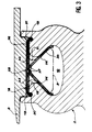
- vanes 1 on the periphery of discs 2 of a gas turbine stator 3 where they alternate with fixed blades 4 responsible for straightening a flow of gas and fixed to a stator 5.
- the blades 1 include a blade 6 which represents their active part and extends in a gas flow stream 7, a platform 8 used to define the vein 7 and adjoining the blade 6, a foot 9 engaged in a circular groove 10 of the disc 2 concerned and a fastener 11 connecting the foot 10 to platform 8 and passing through a pass 12 of the groove 10, through which it opens onto the outside.
- the foot 9 has a bulbous section, i.e.
- Disc 2 is provided however from a bleeding in one place of his circumference, by which the neck 12 is widened to that we can successively insert the feet 9 of vanes 1 in the groove 10 in this place successively, before sliding the blades 1 around the disc 2 to their final location.
- a suitable solution for this is offered with the invention, which relates to a seal sealing for a circular stage of vanes having feet engaged in a circular groove of a disc, blades, platforms adjoining the blades and resting on a peripheral face of the disc on which opens the throat with a circular neck, and fasteners connecting the feet to the platforms and engaged in the neck, the seal comprising a plate housed between the peripheral face and the platforms and hollowed out of days in which the fasteners are engaged, the plate being divided to form inserts butted by cut lines passing through through the days, which have an area less than a section of the blade roots, and being characterized in what it includes tails attached to the pads and forming joint elements with them, the tails extending under oblique upper flanks of the throat.
- European patent 0 210 940 describes a seal including the upper part, close blade platforms, answers the first part of this definition; but this known joint does not include not the lower tails, which provide additional sealing, favored like the others by centrifugal forces during operation.
- the seal is improved if the plate has folded edges towards the inside of the disc and engaged in circular grooves cutting the peripheral side of the disc.
- the lines break lines include horizontal lines and circular lines, and if the pads make an angle obtuse with the tails, are joined to the tails by joints extended by slits between the tails and the inserts, the seal elements being interlaced in pairs, the joining of each of the elements of a pair being housed in the slot of the other of the elements of the same pair by forming a hinge.
- the seal carries the general reference 17 and includes a strip or plate 18 substantially annular engaged between the face disk device 16 and platforms 2 blades 8 when the rotor 3 is mounted; plate 18 has however fallen edges 19, that is to say folded towards the inside of disc 2 and which penetrate in grooves 20 formed in the peripheral face 16; finally it is divided angularly along longitudinal cut-off lines 21, and also by a circular cut-off line (equidistant from the edges fallen 19) so that it is actually made up of 22 abutting plates which extend over half-sectors angular.
- the plates 22 are hollowed out 23 days for the passage of the fasteners 11 of the blades 1 (and whose area is smaller than the section feet 9), and some of the pads 22 are still hollowed out from holes 24 extending other holes 25 drilled through platforms 8 correspondents. These holes 24 and 25 are intended to receive screws, not shown, whose heads are engaged in threads of disc 2, in order to block the seal 17 and the blades 1, joined by their platforms 8, against circular movements. A such an arrangement is moreover conventional with blades engaged in a circular and common groove of a disc. A single pair of holes 24 and 25 can suffice but we can also provide two, as in this achievement.
- the seal 17 also comprises, from typically, tails 26 respectively joined to the plates 22 by joints 27 and which form an obtuse angle with them.
- the fasteners 11 and the feet 9 of the blades 1 have a width (in angular direction of the disc 2) almost equal to that 23 days, and the tails 26 extend in width over almost the entire distance between days 23: almost the entire groove 10 is therefore occupied.
- the joints 27 extend over almost half of the width of the tails 26 and leave between each pair of insert 22 and tail 26 a slot 28 into which joins 27 of another pair of pads 22 and tail 26, pads 22 of these two couples being joined and in extension in the longitudinal direction of the machine.
- the pairs of insert 22 and tail 26 are grouped in intersecting pairs, each of the tails 26 extending under the plate 22 of the other element of the pair, and their joins 27 extend in extension along the line of circular cut with enough play to draw a hinge 29. It is thus possible, after having nested the seams 27 in the slots 28, to bend the assembly thus obtained to approach the tails 26 one from the other and able to insert them into the throat 10 by inward movement through the neck 12.
- Tails 26 are then deployed to spread each other while making the pads 22 parallels: we arrive at the arrangement of the figures, where the tails 26 touch the upper flanks 30 throat obliques 10; it is obvious that centrifugal forces produced by the rotation of the rotor 3 will have the effect of pressing the tails 26 against the sidewalls 30, the plates 22 against the platform 8 and the fallen edges 19 against the outer faces 31 of grooves 20 thanks to the bending of the plates 22. We will therefore obtain a double sealing barrier against the air recirculations, the plates 22 and their fallen edges 19 producing a first dam between the platforms 8 and disc 2 and tails 26 producing a second barrier between the plates 22, pressed against the vanes 8, and the disc 2.
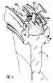
- Figure 5 is a perspective view which shows the folding of one of the pairs of elements for the passage of the collar 12 by the tails 26; it also shows a bleed 33 for locally widen the neck 12 and allow the introduction of the feet 9 of the blades 1, because the first embodiment, in which a pair of plates 22 was associated with two blades 1, required that the latter be in even number.
Landscapes
- Engineering & Computer Science (AREA)
- Mechanical Engineering (AREA)
- General Engineering & Computer Science (AREA)
- Structures Of Non-Positive Displacement Pumps (AREA)
- Turbine Rotor Nozzle Sealing (AREA)
Abstract
Description
- la figure 1 déjà décrite représente une portion de compresseur de turbine à gaz où l'invention peut trouver emploi,
- les figures 2 et 3 illustrent une première réalisation de l'invention,
- et les figures 4 et 5 illustrent une deuxième réalisation de l'invention.
Claims (3)
- Joint d'étanchéité (17, 17', 17") pour un étage circulaire d'aubes (1) ayant des pieds (9) engagés dans une gorge circulaire (10) d'un disque (2), des pales (6), des plates-formes (8) attenantes aux pales (6) et reposant sur une face périphérique (16) du disque (12) sur laquelle s'ouvre la gorge (10) par un col (12) circulaire, et des attaches (11) reliant les pieds (9) aux plates-formes (8) et engagées dans le col (12), le joint comprenant une plaque (18) logée entre la face périphérique (16) et les plates-formes (8) et évidée de jours (23) dans lesquels les attaches (11) sont engagées, la plaque étant divisée pour former des plaquettes aboutées (22, 34) par des lignes de coupure (21, 35) passant à travers les jours (23), qui ont une superficie inférieure à une section des pieds (9) d'aubes, et étant caractérisé en ce qu'il comprend des queues (26) jointes aux plaquettes (22) et formant avec elles des éléments de joint, les queues (26) s'étendant sous des flancs supérieurs obliques (30) de la gorge (10).
- Joint d'étanchéité selon la revendication 1, caractérisé en ce que les lignes de coupure comprennent des lignes longitudinales (21) et des lignes circulaires (35), et en ce que les plaquettes (22) font un angle obtus avec les queues (26), sont jointes aux queues par des jointures (27) prolongées par des fentes (28) entre les queues (26) et les plaquettes (22), les éléments de joint étant entrelacés par paires, la jointure (27) de chacun des éléments d'une paire étant logée dans la fente de l'autre des éléments de la même paire en formant une charnière (29).
- Joint d'étanchéité selon la revendication 1, caractérisé en ce que la plaque présente des bords (19) repliés vers l'intérieur du disque et engagés dans des rainures circulaires (20) entaillant la face périphérique (16) du disque (2).
Applications Claiming Priority (2)
| Application Number | Priority Date | Filing Date | Title |
|---|---|---|---|
| FR9803036A FR2776012B1 (fr) | 1998-03-12 | 1998-03-12 | Joint d'etancheite d'un etage d'aubes circulaire |
| FR9803036 | 1998-03-12 |
Publications (2)
| Publication Number | Publication Date |
|---|---|
| EP0942149A1 true EP0942149A1 (fr) | 1999-09-15 |
| EP0942149B1 EP0942149B1 (fr) | 2000-08-16 |
Family
ID=9523962
Family Applications (1)
| Application Number | Title | Priority Date | Filing Date |
|---|---|---|---|
| EP99400577A Expired - Lifetime EP0942149B1 (fr) | 1998-03-12 | 1999-03-10 | Joint d'étanchéité pour les aubes d'un étage de turbomachine |
Country Status (5)
| Country | Link |
|---|---|
| US (1) | US6332617B1 (fr) |
| EP (1) | EP0942149B1 (fr) |
| JP (1) | JPH11315703A (fr) |
| DE (1) | DE69900008T2 (fr) |
| FR (1) | FR2776012B1 (fr) |
Cited By (2)
| Publication number | Priority date | Publication date | Assignee | Title |
|---|---|---|---|---|
| EP1744013A2 (fr) | 2005-07-14 | 2007-01-17 | United Technologies Corporation | Procédé de montage et de verrouillage tangentiel d'aubes de rotor et aube de rotor |
| US10851661B2 (en) | 2017-08-01 | 2020-12-01 | General Electric Company | Sealing system for a rotary machine and method of assembling same |
Families Citing this family (20)
| Publication number | Priority date | Publication date | Assignee | Title |
|---|---|---|---|---|
| DE10120532A1 (de) * | 2001-04-26 | 2002-10-31 | Alstom Switzerland Ltd | Vorrichtung und Verfahren zur Befestigung einer Laufschaufel längs einer innerhalb eines Rotors einer axial durchströmten Turbomaschine verlaufenden Umfangsnut |
| US20040090017A1 (en) * | 2002-11-08 | 2004-05-13 | Steven Roberts | Universal physical barrier |
| US7059829B2 (en) | 2004-02-09 | 2006-06-13 | Siemens Power Generation, Inc. | Compressor system with movable seal lands |
| US7172388B2 (en) * | 2004-08-24 | 2007-02-06 | Pratt & Whitney Canada Corp. | Multi-point seal |
| MX2008011352A (es) * | 2006-03-06 | 2008-09-23 | Alstom Technology Ltd | Turbina de gas con un escudo termico anular y bandas de sellado anguladas. |
| US8308428B2 (en) * | 2007-10-09 | 2012-11-13 | United Technologies Corporation | Seal assembly retention feature and assembly method |
| GB0908502D0 (en) * | 2009-05-19 | 2009-06-24 | Rolls Royce Plc | A balanced rotor for a turbine engine |
| US8734089B2 (en) | 2009-12-29 | 2014-05-27 | Rolls-Royce Corporation | Damper seal and vane assembly for a gas turbine engine |
| GB2477825B (en) * | 2010-09-23 | 2015-04-01 | Rolls Royce Plc | Anti fret liner assembly |
| US9127563B2 (en) * | 2011-04-05 | 2015-09-08 | General Electric Company | Locking device arrangement for a rotating bladed stage |
| US20120306169A1 (en) * | 2011-06-03 | 2012-12-06 | General Electric Company | Hinge seal |
| US8544852B2 (en) | 2011-06-03 | 2013-10-01 | General Electric Company | Torsion seal |
| US9169849B2 (en) | 2012-05-08 | 2015-10-27 | United Technologies Corporation | Gas turbine engine compressor stator seal |
| DE102013223583A1 (de) * | 2013-11-19 | 2015-05-21 | MTU Aero Engines AG | Schaufel-Scheiben-Verbund, Verfahren und Strömungsmaschine |
| WO2015116399A1 (fr) * | 2014-01-28 | 2015-08-06 | United Technologies Corporation | Joint de cavité flexible pour moteurs à turbine à gaz |
| US10196912B2 (en) | 2014-10-24 | 2019-02-05 | United Technologies Corporation | Bifurcated sliding seal |
| US9587503B2 (en) * | 2014-10-24 | 2017-03-07 | United Technologies Corporation | Hinged seal |
| US10378371B2 (en) | 2014-12-18 | 2019-08-13 | United Technologies Corporation | Anti-rotation vane |
| KR102454379B1 (ko) * | 2020-09-08 | 2022-10-14 | 두산에너빌리티 주식회사 | 로터 및 이를 포함하는 터보머신 |
| FR3138829B1 (fr) | 2022-08-11 | 2024-06-28 | Safran Aircraft Engines | Élément de protection d'un tambour de compresseur basse pression de turbomachine |
Citations (4)
| Publication number | Priority date | Publication date | Assignee | Title |
|---|---|---|---|---|
| GB190909278A (en) * | 1909-04-19 | 1909-08-12 | Warwick Machinery Co 1908 | Improvements in and relating to Elastic Fluid Turbines. |
| US2912222A (en) * | 1952-08-02 | 1959-11-10 | Gen Electric | Turbomachine blading and method of manufacture thereof |
| FR2320439A1 (fr) * | 1975-08-04 | 1977-03-04 | United Technologies Corp | Joint pour plates-formes de pales de compresseur |
| EP0210940A1 (fr) * | 1985-07-18 | 1987-02-04 | United Technologies Corporation | Ruban d'étanchéité en forme d'échelle avec des brides latérales |
Family Cites Families (5)
| Publication number | Priority date | Publication date | Assignee | Title |
|---|---|---|---|---|
| FR2616480B1 (fr) * | 1987-06-10 | 1989-09-29 | Snecma | Dispositif de verrouillage d'aubes a pied marteau sur un disque de turbomachine et procedes de montage et de demontage |
| GB8922339D0 (en) * | 1989-10-04 | 1989-11-22 | Rolls Royce Plc | Improvements in or relating to labyrinth seal structures |
| FR2695161B1 (fr) * | 1992-08-26 | 1994-11-04 | Snecma | Système de refroidissement d'un compresseur de turbomachine et de contrôle des jeux. |
| US5460489A (en) * | 1994-04-12 | 1995-10-24 | United Technologies Corporation | Turbine blade damper and seal |
| FR2739136B1 (fr) * | 1995-09-21 | 1997-10-31 | Snecma | Agencement amortissant pour des aubes de rotor |
-
1998
- 1998-03-12 FR FR9803036A patent/FR2776012B1/fr not_active Expired - Fee Related
-
1999
- 1999-02-22 US US09/255,023 patent/US6332617B1/en not_active Expired - Fee Related
- 1999-02-23 JP JP11044780A patent/JPH11315703A/ja not_active Ceased
- 1999-03-10 EP EP99400577A patent/EP0942149B1/fr not_active Expired - Lifetime
- 1999-03-10 DE DE69900008T patent/DE69900008T2/de not_active Expired - Fee Related
Patent Citations (4)
| Publication number | Priority date | Publication date | Assignee | Title |
|---|---|---|---|---|
| GB190909278A (en) * | 1909-04-19 | 1909-08-12 | Warwick Machinery Co 1908 | Improvements in and relating to Elastic Fluid Turbines. |
| US2912222A (en) * | 1952-08-02 | 1959-11-10 | Gen Electric | Turbomachine blading and method of manufacture thereof |
| FR2320439A1 (fr) * | 1975-08-04 | 1977-03-04 | United Technologies Corp | Joint pour plates-formes de pales de compresseur |
| EP0210940A1 (fr) * | 1985-07-18 | 1987-02-04 | United Technologies Corporation | Ruban d'étanchéité en forme d'échelle avec des brides latérales |
Cited By (4)
| Publication number | Priority date | Publication date | Assignee | Title |
|---|---|---|---|---|
| EP1744013A2 (fr) | 2005-07-14 | 2007-01-17 | United Technologies Corporation | Procédé de montage et de verrouillage tangentiel d'aubes de rotor et aube de rotor |
| EP1744013B1 (fr) * | 2005-07-14 | 2011-10-12 | United Technologies Corporation | Procédé de montage et de verrouillage tangentiel d'aubes de rotor et aube de rotor correspondante |
| US8206116B2 (en) | 2005-07-14 | 2012-06-26 | United Technologies Corporation | Method for loading and locking tangential rotor blades and blade design |
| US10851661B2 (en) | 2017-08-01 | 2020-12-01 | General Electric Company | Sealing system for a rotary machine and method of assembling same |
Also Published As
| Publication number | Publication date |
|---|---|
| JPH11315703A (ja) | 1999-11-16 |
| DE69900008D1 (de) | 2000-09-21 |
| US6332617B1 (en) | 2001-12-25 |
| FR2776012B1 (fr) | 2000-04-07 |
| DE69900008T2 (de) | 2001-04-05 |
| FR2776012A1 (fr) | 1999-09-17 |
| EP0942149B1 (fr) | 2000-08-16 |
Similar Documents
| Publication | Publication Date | Title |
|---|---|---|
| EP0942149B1 (fr) | Joint d'étanchéité pour les aubes d'un étage de turbomachine | |
| EP1213484B1 (fr) | Etage redressseur d'un compresseur | |
| EP1764480A1 (fr) | Clinquant pour aube de turboréacteur | |
| EP1335112B1 (fr) | Agencement de pivotement d'aube de stator dans une turbomachine | |
| FR2593552A1 (fr) | Dispositif d'accouplement anti-rotation pour machines a volutes | |
| EP2817491B1 (fr) | Joint linéaire de plateforme inter- aubes, plateforme inter- aubes, rotor et turboréacteur associés | |
| EP3677752B1 (fr) | Joint d'étanchéité amélioré de plateforme inter-aubes | |
| CA2931374A1 (fr) | Dispositif de guidage d'aubes de redresseur a angle de calage variable de turbomachine et procede d'assemblage d'un tel dispositif | |
| EP2058091B1 (fr) | Ciseaux avec poignées à anneaux souples | |
| EP1800559A1 (fr) | Lien comportant un carter de fixation formé d'une plaque et d'une contre-plaque | |
| EP1306525A1 (fr) | Dispositif d'arrêt en rotation d'un secteur porteur d'aubes fixes dans une virole d'une turbomachine | |
| EP0669451B1 (fr) | Garniture d'étanchéité entre des aubes et des plates-formes intermédiaires | |
| FR2715968A1 (fr) | Rotor à plates-formes rapportées entre les aubes. | |
| EP0549979A1 (fr) | Bracelet à maillons notamment pour montre | |
| EP0735242A1 (fr) | Agencement de raccordement de deux secteurs angulaires de turbomachine et joint conçu pour servir dans cet agencement | |
| EP1757796A2 (fr) | Compresseur comportant une pluralité de caissons reconstituant un volume annulaire de séparation de flux dans une turbomachine | |
| FR2514409A1 (fr) | Dispositif d'implantation d'aubes en secteurs sur un disque de rotor de turbomachine | |
| EP3909430B1 (fr) | Dispositif de mise en portion de saucisses | |
| FR2535389A1 (fr) | Dispositif de montage, sur leur disque porteur, d'aubes profilees pour compresseur ou turbine | |
| EP0651139A1 (fr) | Turbomachine équipée de moyens de pilotage des jeux entre rotor et stator | |
| FR2710103A1 (fr) | Flasque de rotor de turbomachine et assemblage de ce flasque avec un rotor. | |
| EP3857028B1 (fr) | Distributeur amelioré de turbomachine | |
| CH641332A5 (en) | Clasp | |
| BE1008543A6 (fr) | Profile d'etancheite entre une menuiserie et un vitrage ou similaire. | |
| EP0493997B1 (fr) | Déflecteur ou goulotte pour orienter et/ou canaliser un jet de produits |
Legal Events
| Date | Code | Title | Description |
|---|---|---|---|
| PUAI | Public reference made under article 153(3) epc to a published international application that has entered the european phase |
Free format text: ORIGINAL CODE: 0009012 |
|
| 17P | Request for examination filed |
Effective date: 19990329 |
|
| AK | Designated contracting states |
Kind code of ref document: A1 Designated state(s): DE FR GB |
|
| AX | Request for extension of the european patent |
Free format text: AL;LT;LV;MK;RO;SI |
|
| GRAG | Despatch of communication of intention to grant |
Free format text: ORIGINAL CODE: EPIDOS AGRA |
|
| GRAG | Despatch of communication of intention to grant |
Free format text: ORIGINAL CODE: EPIDOS AGRA |
|
| GRAH | Despatch of communication of intention to grant a patent |
Free format text: ORIGINAL CODE: EPIDOS IGRA |
|
| 17Q | First examination report despatched |
Effective date: 20000126 |
|
| GRAH | Despatch of communication of intention to grant a patent |
Free format text: ORIGINAL CODE: EPIDOS IGRA |
|
| RAP1 | Party data changed (applicant data changed or rights of an application transferred) |
Owner name: SNECMA MOTEURS |
|
| AKX | Designation fees paid |
Free format text: DE FR GB |
|
| GRAA | (expected) grant |
Free format text: ORIGINAL CODE: 0009210 |
|
| AK | Designated contracting states |
Kind code of ref document: B1 Designated state(s): DE FR GB |
|
| GBT | Gb: translation of ep patent filed (gb section 77(6)(a)/1977) |
Effective date: 20000825 |
|
| REF | Corresponds to: |
Ref document number: 69900008 Country of ref document: DE Date of ref document: 20000921 |
|
| PLBE | No opposition filed within time limit |
Free format text: ORIGINAL CODE: 0009261 |
|
| STAA | Information on the status of an ep patent application or granted ep patent |
Free format text: STATUS: NO OPPOSITION FILED WITHIN TIME LIMIT |
|
| 26N | No opposition filed | ||
| REG | Reference to a national code |
Ref country code: GB Ref legal event code: IF02 |
|
| REG | Reference to a national code |
Ref country code: FR Ref legal event code: TP Ref country code: FR Ref legal event code: CD |
|
| PGFP | Annual fee paid to national office [announced via postgrant information from national office to epo] |
Ref country code: FR Payment date: 20050222 Year of fee payment: 7 |
|
| PGFP | Annual fee paid to national office [announced via postgrant information from national office to epo] |
Ref country code: GB Payment date: 20050225 Year of fee payment: 7 Ref country code: DE Payment date: 20050225 Year of fee payment: 7 |
|
| REG | Reference to a national code |
Ref country code: FR Ref legal event code: CD |
|
| PG25 | Lapsed in a contracting state [announced via postgrant information from national office to epo] |
Ref country code: GB Free format text: LAPSE BECAUSE OF NON-PAYMENT OF DUE FEES Effective date: 20060310 |
|
| PG25 | Lapsed in a contracting state [announced via postgrant information from national office to epo] |
Ref country code: DE Free format text: LAPSE BECAUSE OF NON-PAYMENT OF DUE FEES Effective date: 20061003 |
|
| GBPC | Gb: european patent ceased through non-payment of renewal fee |
Effective date: 20060310 |
|
| REG | Reference to a national code |
Ref country code: FR Ref legal event code: ST Effective date: 20061130 |
|
| PG25 | Lapsed in a contracting state [announced via postgrant information from national office to epo] |
Ref country code: FR Free format text: LAPSE BECAUSE OF NON-PAYMENT OF DUE FEES Effective date: 20060331 |