EP0211016B1 - Appareil de traitement de gaz de fumee - Google Patents
Appareil de traitement de gaz de fumee Download PDFInfo
- Publication number
- EP0211016B1 EP0211016B1 EP19860900720 EP86900720A EP0211016B1 EP 0211016 B1 EP0211016 B1 EP 0211016B1 EP 19860900720 EP19860900720 EP 19860900720 EP 86900720 A EP86900720 A EP 86900720A EP 0211016 B1 EP0211016 B1 EP 0211016B1
- Authority
- EP
- European Patent Office
- Prior art keywords
- flue gases
- cooling
- fan
- outlet
- vessel
- Prior art date
- Legal status (The legal status is an assumption and is not a legal conclusion. Google has not performed a legal analysis and makes no representation as to the accuracy of the status listed.)
- Expired
Links
- 239000003546 flue gas Substances 0.000 title claims abstract description 53
- 238000001816 cooling Methods 0.000 claims abstract description 33
- 239000000428 dust Substances 0.000 claims description 13
- 239000002245 particle Substances 0.000 claims description 12
- 239000002826 coolant Substances 0.000 claims description 5
- 239000007788 liquid Substances 0.000 claims description 3
- 238000007599 discharging Methods 0.000 claims 1
- 239000007789 gas Substances 0.000 description 11
- 239000002253 acid Substances 0.000 description 8
- 150000007513 acids Chemical class 0.000 description 8
- XLYOFNOQVPJJNP-UHFFFAOYSA-N water Substances O XLYOFNOQVPJJNP-UHFFFAOYSA-N 0.000 description 8
- NINIDFKCEFEMDL-UHFFFAOYSA-N Sulfur Chemical compound [S] NINIDFKCEFEMDL-UHFFFAOYSA-N 0.000 description 5
- 239000005864 Sulphur Substances 0.000 description 5
- 239000000047 product Substances 0.000 description 5
- 238000009833 condensation Methods 0.000 description 3
- 230000005494 condensation Effects 0.000 description 3
- 239000012535 impurity Substances 0.000 description 3
- 238000006386 neutralization reaction Methods 0.000 description 3
- QGZKDVFQNNGYKY-UHFFFAOYSA-N Ammonia Chemical compound N QGZKDVFQNNGYKY-UHFFFAOYSA-N 0.000 description 2
- 238000004140 cleaning Methods 0.000 description 2
- 239000003077 lignite Substances 0.000 description 2
- 230000003213 activating effect Effects 0.000 description 1
- 229910021529 ammonia Inorganic materials 0.000 description 1
- 239000007864 aqueous solution Substances 0.000 description 1
- 238000005119 centrifugation Methods 0.000 description 1
- 238000002485 combustion reaction Methods 0.000 description 1
- 230000007797 corrosion Effects 0.000 description 1
- 238000005260 corrosion Methods 0.000 description 1
- 230000002939 deleterious effect Effects 0.000 description 1
- 230000000694 effects Effects 0.000 description 1
- 238000001914 filtration Methods 0.000 description 1
- 230000005484 gravity Effects 0.000 description 1
- 238000010438 heat treatment Methods 0.000 description 1
- 238000009434 installation Methods 0.000 description 1
- 230000007935 neutral effect Effects 0.000 description 1
- 230000003472 neutralizing effect Effects 0.000 description 1
- 239000002244 precipitate Substances 0.000 description 1
- 238000000926 separation method Methods 0.000 description 1
- 239000000779 smoke Substances 0.000 description 1
- 239000007787 solid Substances 0.000 description 1
Images
Classifications
-
- B—PERFORMING OPERATIONS; TRANSPORTING
- B01—PHYSICAL OR CHEMICAL PROCESSES OR APPARATUS IN GENERAL
- B01D—SEPARATION
- B01D45/00—Separating dispersed particles from gases or vapours by gravity, inertia, or centrifugal forces
- B01D45/12—Separating dispersed particles from gases or vapours by gravity, inertia, or centrifugal forces by centrifugal forces
- B01D45/14—Separating dispersed particles from gases or vapours by gravity, inertia, or centrifugal forces by centrifugal forces generated by rotating vanes, discs, drums or brushes
-
- B—PERFORMING OPERATIONS; TRANSPORTING
- B01—PHYSICAL OR CHEMICAL PROCESSES OR APPARATUS IN GENERAL
- B01D—SEPARATION
- B01D53/00—Separation of gases or vapours; Recovering vapours of volatile solvents from gases; Chemical or biological purification of waste gases, e.g. engine exhaust gases, smoke, fumes, flue gases, aerosols
- B01D53/34—Chemical or biological purification of waste gases
- B01D53/46—Removing components of defined structure
- B01D53/48—Sulfur compounds
- B01D53/50—Sulfur oxides
- B01D53/501—Sulfur oxides by treating the gases with a solution or a suspension of an alkali or earth-alkali or ammonium compound
-
- C—CHEMISTRY; METALLURGY
- C22—METALLURGY; FERROUS OR NON-FERROUS ALLOYS; TREATMENT OF ALLOYS OR NON-FERROUS METALS
- C22B—PRODUCTION AND REFINING OF METALS; PRETREATMENT OF RAW MATERIALS
- C22B7/00—Working up raw materials other than ores, e.g. scrap, to produce non-ferrous metals and compounds thereof; Methods of a general interest or applied to the winning of more than two metals
- C22B7/001—Dry processes
- C22B7/003—Dry processes only remelting, e.g. of chips, borings, turnings; apparatus used therefor
-
- F—MECHANICAL ENGINEERING; LIGHTING; HEATING; WEAPONS; BLASTING
- F23—COMBUSTION APPARATUS; COMBUSTION PROCESSES
- F23J—REMOVAL OR TREATMENT OF COMBUSTION PRODUCTS OR COMBUSTION RESIDUES; FLUES
- F23J15/00—Arrangements of devices for treating smoke or fumes
- F23J15/02—Arrangements of devices for treating smoke or fumes of purifiers, e.g. for removing noxious material
- F23J15/022—Arrangements of devices for treating smoke or fumes of purifiers, e.g. for removing noxious material for removing solid particulate material from the gasflow
-
- F—MECHANICAL ENGINEERING; LIGHTING; HEATING; WEAPONS; BLASTING
- F23—COMBUSTION APPARATUS; COMBUSTION PROCESSES
- F23J—REMOVAL OR TREATMENT OF COMBUSTION PRODUCTS OR COMBUSTION RESIDUES; FLUES
- F23J15/00—Arrangements of devices for treating smoke or fumes
- F23J15/06—Arrangements of devices for treating smoke or fumes of coolers
-
- F—MECHANICAL ENGINEERING; LIGHTING; HEATING; WEAPONS; BLASTING
- F01—MACHINES OR ENGINES IN GENERAL; ENGINE PLANTS IN GENERAL; STEAM ENGINES
- F01M—LUBRICATING OF MACHINES OR ENGINES IN GENERAL; LUBRICATING INTERNAL COMBUSTION ENGINES; CRANKCASE VENTILATING
- F01M13/00—Crankcase ventilating or breathing
- F01M13/04—Crankcase ventilating or breathing having means for purifying air before leaving crankcase, e.g. removing oil
- F01M2013/0422—Separating oil and gas with a centrifuge device
-
- Y—GENERAL TAGGING OF NEW TECHNOLOGICAL DEVELOPMENTS; GENERAL TAGGING OF CROSS-SECTIONAL TECHNOLOGIES SPANNING OVER SEVERAL SECTIONS OF THE IPC; TECHNICAL SUBJECTS COVERED BY FORMER USPC CROSS-REFERENCE ART COLLECTIONS [XRACs] AND DIGESTS
- Y02—TECHNOLOGIES OR APPLICATIONS FOR MITIGATION OR ADAPTATION AGAINST CLIMATE CHANGE
- Y02P—CLIMATE CHANGE MITIGATION TECHNOLOGIES IN THE PRODUCTION OR PROCESSING OF GOODS
- Y02P10/00—Technologies related to metal processing
- Y02P10/20—Recycling
-
- Y—GENERAL TAGGING OF NEW TECHNOLOGICAL DEVELOPMENTS; GENERAL TAGGING OF CROSS-SECTIONAL TECHNOLOGIES SPANNING OVER SEVERAL SECTIONS OF THE IPC; TECHNICAL SUBJECTS COVERED BY FORMER USPC CROSS-REFERENCE ART COLLECTIONS [XRACs] AND DIGESTS
- Y10—TECHNICAL SUBJECTS COVERED BY FORMER USPC
- Y10S—TECHNICAL SUBJECTS COVERED BY FORMER USPC CROSS-REFERENCE ART COLLECTIONS [XRACs] AND DIGESTS
- Y10S55/00—Gas separation
- Y10S55/14—Inertia separator
Definitions
- This invention relates to an apparatus for the treatment of flue gases, more particularly to an apparatus for dedusting industrial flue gases.
- the apparatus according to the present invention is especially suited for being used as a smoke filter in the combustion of, e.g., lignite (called also brown coal), wherein, first of all, dedusting of flue gases is provided and secondly also the major part of sulphur is removed from said gases.
- lignite called also brown coal
- a known apparatus for the treatment of flue gases is the classical cyclone separator or dust extractor.
- the flue gases are substantially tangentially fed into an upright cylindrical vessel, wherein they first describe a helical path along the cylindrical wall and finally ascend again in the vessel and disappear through a central outlet.
- lighter dust particles are readily removed along with the flue gases through the outlet and hence get into the atmosphere, whereby a serious pollution of the environment may arise.
- the present invention provides an apparatus for the treatment of flue gases, whereby, on the one hand, large as well as small dust particles are removed from said flue gases and, on the other hand, said flue gases can be desulphurised, if necessary.
- apparatus for the treatment of flue gases which comprises an upright vessel provided with an inlet opening for the flue gases, an outlet opening for the flue gases, a cooled wall, means for entering flue gases into contact with said cooled wall, and outlet means for removing the residual product from the flue gases to be treated.
- the gases that are to be cleaned are blown into a chamber, whereafter, through contact with a refrigerated wall, the impurities in the gas are precipitated on this wall.
- a further device for heating the air in a cleaning device for gases.
- This cleaning device does not contain a refrigerated wall against which the impurities can precipitate. The separation of the impurities from the gases happens simply by centrifugation.
- the present invention concerns a device, whereby the gases are influenced in such a way, that they arrive with great force against the refrigerated wall.
- the apparatus for treating flue gases comprises an upright vessel provided with an inlet opening for the flue gases, an outlet opening for the flue gases, a cooled wall, means for entering flue gases into contact with said cooled wall, and outlet means for removing the residual product from the flue gases to be treated, characterized in that said inlet opening is central in the upper side of said upright cylindrical vessel and proximate a radial fan positioned below, and in that below said fan proximate but spaced from said fan a centrally arranged outlet opening for the flue gases is provided.
- the supply tube of the apparatus is provided with an inlet through which means can be introduced for neutralising the acids formed from sulphur.
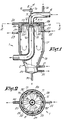
- the apparatus mainly consists of an upright cylindrical vessel 1 which at its bottom preferably tapers off to a funnel-shaped end 2.
- an inlet opening 5 is provided, through which the flue gases are brought into said vessel 1 via a supply tube 6.
- said supply tube 6 has a bend 7 giving passage to a shaft 8, which on the one hand extends outside the interior of the apparatus and there is driven by means of a belt 9 and a pulley 10, and on the other hand, at its other end which extends to the interior of vessel 1, bears a fan 11 finding itself just below the inside opening 5.
- the axis of rotation of shaft 8 coincides with the axis of symmetry of vessel 1.
- Fan 11 mainly consists of two horizontal circular plates 12 between which a plurality of vertical blades 13 are applied, the top plate being provided with a central opening closely fitting against the inlet opening 5 for the flue gases.
- said blades 13 extend radially with respect to said shaft 8. Likewise, the blades 13 do not continue below the inlet opening 5.
- an inlet 14 is made in supply tube 6 whose purpose will appear further below from the description of its operation.
- a central outlet opening 15 is provided through which the gases can be discharged into the atmosphere via a flue 16 through the side wall 17 of vessel 1.
- the apparatus is equipped with means for cooling the side wall 17 of vessel 1.
- Said means consist of two separate cooling circuits 18-19 and a number of cooling fins 20 in the embodiment represented in the figures.
- Both cooling circuits 18-19 are mainly formed by side wall 17 which is double-walled and each cooling circuit is provided with an inlet 21 and 22 respec-
- a cooling medium e.g. water
- Both cooling circuits 18-19 are mounted above each other.
- the lower cooling circuit 18 provides for the cooling of the major part of side wall 17, whereas the upper cooling circuit 19 provides for the cooling of a relatively small part of side wall 1 7, whereby an intensive cooling action is achieved.
- the above-mentioned cooling fins 20 are provided.
- Said cooling fins 20 are traversed by the cooling medium of the upper cooling circuit 19.
- the latter consists of superposed annular chambers 25-26, which are connected by the fins 20 that are hollow.
- the lower annular chamber 25 is connected with the inlet 22, whereas the upper annular chamber 26 is provided with the outlet 24.
- cooling fins 20 constitute the only junction between the lower and upper annular chambers 25 and 26 respectively.
- the hollow fins 20 run preferably downward according to a relatively strongly sloping helix, which in the downward direction has the same sense of rotation as that of the fan.
- a filter 29 for separating solid matter from a liquid by filtration.
- the filtered liquid leaves the filter via pipe 30, whereas the residual product can be discharged occasionally through a pipe 31.
- any type of suitable filter known by itself can be used. So, amongst others, use can be made of a filter 29 wherein the residual product can pile up, which filter has to be cleaned periodically.
- the operation of the apparatus according to the present invention is the following.
- the hot flue gases flow through the supply tube 6 and the inlet opening 5 into vessel 1.
- the temperature of these gases should amount to at least 120°C in order to avoid corrosion by sulphur and condensation in the part of any installation preceding this apparatus.
- the invention provides the desulphurisation, or more specifically, the neutralisation of the acids formed from the sulphur contained in the flue gases.
- a base e.g. ammonia
- This base reacts with the acids present in the flue gases so as to form a harmless neutral product. It is of importance therein that the apparatus according to the present invention in consequence is not corroded by said acids.
- the invention can be carried out in many modified forms without departing from its scope. So, the inlet opening 5 and the outlet opening 15 optionally could be provided at other places; the blades 13 of fan 11 could be curved; there could be cooling fins 20 having another shape, or there could be no cooling fins at all; another filter or no filter 29 at all could be used.
- the means that provide for forcing the flue gases toward the side wall 17 can be other means than a fan 11 or the like.
- the cooling fins 20 are equipped with inclined fins 32 extending very closely to fan 11 in order to realize a still better guidance of the flue gases and to inevitably guide them against the cooled parts.
- the fins 32 are represented in figure 2 only.
- the cooling of the side wall 17 can take place in a number of ways. So, e.g., for the sake of symplicity, only one cooling circuit could be provided instead of two. On the other hand, the water cooling could be replaced by an air cooling.
- a water supply can be provided if the flue gases do not contain enough vapour for creating a water film by condensation on side wall 17. Said supply can occur, e.g., through a supplementary inlet in the supply tube 6.
Landscapes
- Engineering & Computer Science (AREA)
- Chemical & Material Sciences (AREA)
- Mechanical Engineering (AREA)
- General Engineering & Computer Science (AREA)
- Environmental & Geological Engineering (AREA)
- Chemical Kinetics & Catalysis (AREA)
- Oil, Petroleum & Natural Gas (AREA)
- Geology (AREA)
- Analytical Chemistry (AREA)
- General Chemical & Material Sciences (AREA)
- Health & Medical Sciences (AREA)
- Life Sciences & Earth Sciences (AREA)
- General Life Sciences & Earth Sciences (AREA)
- Biomedical Technology (AREA)
- Manufacturing & Machinery (AREA)
- Materials Engineering (AREA)
- Metallurgy (AREA)
- Organic Chemistry (AREA)
- Treating Waste Gases (AREA)
- Separating Particles In Gases By Inertia (AREA)
Abstract
Claims (9)
Applications Claiming Priority (2)
| Application Number | Priority Date | Filing Date | Title |
|---|---|---|---|
| BE2/60595A BE901542A (nl) | 1985-01-22 | 1985-01-22 | Inrichting om rookgassen te behandelen. |
| BE2060595 | 1985-01-22 |
Publications (2)
| Publication Number | Publication Date |
|---|---|
| EP0211016A1 EP0211016A1 (fr) | 1987-02-25 |
| EP0211016B1 true EP0211016B1 (fr) | 1989-06-14 |
Family
ID=3865725
Family Applications (1)
| Application Number | Title | Priority Date | Filing Date |
|---|---|---|---|
| EP19860900720 Expired EP0211016B1 (fr) | 1985-01-22 | 1986-01-21 | Appareil de traitement de gaz de fumee |
Country Status (5)
| Country | Link |
|---|---|
| US (1) | US4734030A (fr) |
| EP (1) | EP0211016B1 (fr) |
| BE (1) | BE901542A (fr) |
| DE (1) | DE3663887D1 (fr) |
| WO (1) | WO1986004257A1 (fr) |
Families Citing this family (12)
| Publication number | Priority date | Publication date | Assignee | Title |
|---|---|---|---|---|
| SE459986B (sv) * | 1987-04-09 | 1989-08-28 | Asea Stal Ab | Kraftanlaeggning med cyklonrenare med kylda cyklonben |
| DE4403432A1 (de) * | 1994-02-04 | 1995-08-10 | Abb Research Ltd | Abgasführung für einen Filterstaub-Schmelzofen |
| EP0729376B1 (fr) * | 1994-09-08 | 1999-06-09 | Bavaria-Tech, Werner Schlattl | Dispositif d'extraction de l'huile, de la suie et/ou d'autres matieres etrangeres contenues dans un courant d'air, de gaz et/ou de vapeur |
| EP0779092B1 (fr) * | 1995-12-14 | 2002-03-20 | Suntec System Co., Ltd. | Système de traitement de gaz d'échappement |
| EP0784189B1 (fr) * | 1996-01-11 | 2001-04-04 | Incisud, S.L. | Système pour la combustion autonome de déchets municipaux solides |
| SE509381C2 (sv) * | 1996-09-11 | 1999-01-18 | Abb Carbon Ab | Förbränningsanläggning och avskiljningsanordning |
| DE19844441A1 (de) * | 1998-09-28 | 2000-04-06 | Lundin Filter Gmbh | Vorrichtung und Verfahren zum Abtrennen von Teilchen aus einem Fluid |
| US6562109B2 (en) * | 2001-03-28 | 2003-05-13 | Mks Instruments, Inc. | Acceleration assisted particle/gas separation system |
| DE10323261A1 (de) * | 2003-05-23 | 2004-12-16 | Daimlerchrysler Ag | Zentrifugal-Ölabscheider für Blow-By-Gase einer Brennkraftmaschine |
| DE102008012400B4 (de) | 2008-03-04 | 2014-05-08 | Ford Global Technologies, Llc | Ölnebelabscheider |
| TWI482741B (zh) * | 2009-08-25 | 2015-05-01 | Corning Inc | 廢氣排出裝置及用於製造玻璃材料的程序 |
| EP2937867B1 (fr) | 2014-03-03 | 2018-11-14 | Fnctech | Système d'évacuation filtrée de confinement utilisé pour une centrale nucléaire |
Family Cites Families (12)
| Publication number | Priority date | Publication date | Assignee | Title |
|---|---|---|---|---|
| DE520792C (de) * | 1931-03-14 | Gewerkschaft Des Braunkohlen B | Einrichtung zum Vorwaermen von Luft in Schleudergasreinigern fuer heisse Gase | |
| GB241602A (en) * | 1924-05-22 | 1925-10-22 | Harry Ewart Partridge | Improvements relating to the separation of solid particles from flue gases |
| US2194666A (en) * | 1935-10-31 | 1940-03-26 | Meissner Josef | Nitration of aromatic hydrocarbons |
| US2582899A (en) * | 1946-12-14 | 1952-01-15 | Blaw Knox Co | Autoclave reactor |
| BE638424A (fr) * | 1962-10-17 | |||
| NL6506163A (fr) * | 1964-05-23 | 1965-11-24 | ||
| DE1493734A1 (de) * | 1965-08-12 | 1969-06-19 | Hoechst Ag | Vorrichtung zur Herstellung von Alkalisalzen aromatischer Hydroxyverbindungen |
| US3884643A (en) * | 1968-03-15 | 1975-05-20 | Mario Ballestra | Device for performing highly exothermic reactions |
| US3921397A (en) * | 1972-02-14 | 1975-11-25 | G Emilio Guarderas | Silencer against toxic gases |
| US3928536A (en) * | 1973-03-14 | 1975-12-23 | Jr George W Lewis | Processes for removal of sulfur dioxide from gases |
| NL8200826A (nl) * | 1982-03-02 | 1983-10-03 | Shell Int Research | Werkwijze en inrichting voor het verwijderen van koolstofhoudende vliegas uit een gas. |
| GB8330663D0 (en) * | 1983-11-17 | 1983-12-29 | Dresser Ind | Liquid spraying |
-
1985
- 1985-01-22 BE BE2/60595A patent/BE901542A/nl not_active IP Right Cessation
-
1986
- 1986-01-21 WO PCT/BE1986/000001 patent/WO1986004257A1/fr not_active Ceased
- 1986-01-21 EP EP19860900720 patent/EP0211016B1/fr not_active Expired
- 1986-01-21 US US06/916,482 patent/US4734030A/en not_active Expired - Fee Related
- 1986-01-21 DE DE8686900720T patent/DE3663887D1/de not_active Expired
Also Published As
| Publication number | Publication date |
|---|---|
| BE901542A (nl) | 1985-05-17 |
| WO1986004257A1 (fr) | 1986-07-31 |
| DE3663887D1 (en) | 1989-07-20 |
| EP0211016A1 (fr) | 1987-02-25 |
| US4734030A (en) | 1988-03-29 |
Similar Documents
| Publication | Publication Date | Title |
|---|---|---|
| EP0211016B1 (fr) | Appareil de traitement de gaz de fumee | |
| US4344779A (en) | Air pollution control system | |
| US4312646A (en) | Gas scrubbing tower | |
| US4008056A (en) | Scrubber system for removing gaseous pollutants from a moving gas stream by condensation | |
| JPH10319A (ja) | 分離装置 | |
| US3412529A (en) | Gas scrubbing apparatus and method | |
| JPH10314526A (ja) | 分離装置 | |
| US4948396A (en) | Compound vortex filtering apparatus | |
| US3487607A (en) | Exhaust filtration and collector system | |
| US4344920A (en) | Air pollution control system | |
| US2560077A (en) | Apparatus for contacting gases and liquids to effect concentration, fractionation, and the like | |
| US4314830A (en) | Side stream separator for boiler particulate emission control | |
| US2114786A (en) | Column | |
| SE505579C2 (sv) | Sätt att avskilja stoft från varma processgaser | |
| EP0677318B1 (fr) | Dispositif d'épuration des gaz de fumée d'installations d'incinération de déchets | |
| US3054244A (en) | Gas-material separator | |
| US969769A (en) | Method and apparatus for cleaning gas. | |
| EP4237123A1 (fr) | Procédé de purification de fumées | |
| US3923956A (en) | Smokeless anti-toxic burner method | |
| US1779282A (en) | Boiler-house smoke-disposal process | |
| US2117718A (en) | Tar extractor and the like | |
| US679587A (en) | Apparatus for collecting gases, vapors, and foreign particles from air. | |
| US4067706A (en) | Apparatus for gas scrubbing and particulate solids removal | |
| US3950151A (en) | Pollution control apparatus and method | |
| US1875341A (en) | Fornia |
Legal Events
| Date | Code | Title | Description |
|---|---|---|---|
| PUAI | Public reference made under article 153(3) epc to a published international application that has entered the european phase |
Free format text: ORIGINAL CODE: 0009012 |
|
| AK | Designated contracting states |
Kind code of ref document: A1 Designated state(s): DE FR GB LU NL |
|
| 17P | Request for examination filed |
Effective date: 19870116 |
|
| 17Q | First examination report despatched |
Effective date: 19880204 |
|
| GRAA | (expected) grant |
Free format text: ORIGINAL CODE: 0009210 |
|
| AK | Designated contracting states |
Kind code of ref document: B1 Designated state(s): DE FR GB LU NL |
|
| REF | Corresponds to: |
Ref document number: 3663887 Country of ref document: DE Date of ref document: 19890720 |
|
| ET | Fr: translation filed | ||
| PG25 | Lapsed in a contracting state [announced via postgrant information from national office to epo] |
Ref country code: GB Effective date: 19900121 |
|
| PG25 | Lapsed in a contracting state [announced via postgrant information from national office to epo] |
Ref country code: LU Free format text: LAPSE BECAUSE OF NON-PAYMENT OF DUE FEES Effective date: 19900131 |
|
| PLBE | No opposition filed within time limit |
Free format text: ORIGINAL CODE: 0009261 |
|
| STAA | Information on the status of an ep patent application or granted ep patent |
Free format text: STATUS: NO OPPOSITION FILED WITHIN TIME LIMIT |
|
| 26N | No opposition filed | ||
| PG25 | Lapsed in a contracting state [announced via postgrant information from national office to epo] |
Ref country code: NL Effective date: 19900801 |
|
| NLV4 | Nl: lapsed or anulled due to non-payment of the annual fee | ||
| GBPC | Gb: european patent ceased through non-payment of renewal fee | ||
| PG25 | Lapsed in a contracting state [announced via postgrant information from national office to epo] |
Ref country code: FR Effective date: 19900928 |
|
| PG25 | Lapsed in a contracting state [announced via postgrant information from national office to epo] |
Ref country code: DE Effective date: 19901002 |
|
| REG | Reference to a national code |
Ref country code: FR Ref legal event code: ST |