EP0211308A2 - Datenverarbeitungsanlage - Google Patents
Datenverarbeitungsanlage Download PDFInfo
- Publication number
- EP0211308A2 EP0211308A2 EP86110005A EP86110005A EP0211308A2 EP 0211308 A2 EP0211308 A2 EP 0211308A2 EP 86110005 A EP86110005 A EP 86110005A EP 86110005 A EP86110005 A EP 86110005A EP 0211308 A2 EP0211308 A2 EP 0211308A2
- Authority
- EP
- European Patent Office
- Prior art keywords
- electroluminescent panel
- data processing
- panel
- liquid crystal
- crystal display
- Prior art date
- Legal status (The legal status is an assumption and is not a legal conclusion. Google has not performed a legal analysis and makes no representation as to the accuracy of the status listed.)
- Granted
Links
Images

Classifications
-
- G—PHYSICS
- G06—COMPUTING OR CALCULATING; COUNTING
- G06F—ELECTRIC DIGITAL DATA PROCESSING
- G06F1/00—Details not covered by groups G06F3/00 - G06F13/00 and G06F21/00
- G06F1/26—Power supply means, e.g. regulation thereof
- G06F1/32—Means for saving power
- G06F1/3203—Power management, i.e. event-based initiation of a power-saving mode
- G06F1/3206—Monitoring of events, devices or parameters that trigger a change in power modality
- G06F1/3215—Monitoring of peripheral devices
- G06F1/3218—Monitoring of peripheral devices of display devices
-
- G—PHYSICS
- G09—EDUCATION; CRYPTOGRAPHY; DISPLAY; ADVERTISING; SEALS
- G09G—ARRANGEMENTS OR CIRCUITS FOR CONTROL OF INDICATING DEVICES USING STATIC MEANS TO PRESENT VARIABLE INFORMATION
- G09G3/00—Control arrangements or circuits, of interest only in connection with visual indicators other than cathode-ray tubes
- G09G3/20—Control arrangements or circuits, of interest only in connection with visual indicators other than cathode-ray tubes for presentation of an assembly of a number of characters, e.g. a page, by composing the assembly by combination of individual elements arranged in a matrix no fixed position being assigned to or needed to be assigned to the individual characters or partial characters
- G09G3/34—Control arrangements or circuits, of interest only in connection with visual indicators other than cathode-ray tubes for presentation of an assembly of a number of characters, e.g. a page, by composing the assembly by combination of individual elements arranged in a matrix no fixed position being assigned to or needed to be assigned to the individual characters or partial characters by control of light from an independent source
- G09G3/3406—Control of illumination source
-
- G—PHYSICS
- G09—EDUCATION; CRYPTOGRAPHY; DISPLAY; ADVERTISING; SEALS
- G09G—ARRANGEMENTS OR CIRCUITS FOR CONTROL OF INDICATING DEVICES USING STATIC MEANS TO PRESENT VARIABLE INFORMATION
- G09G2320/00—Control of display operating conditions
- G09G2320/06—Adjustment of display parameters
- G09G2320/0606—Manual adjustment
-
- G—PHYSICS
- G09—EDUCATION; CRYPTOGRAPHY; DISPLAY; ADVERTISING; SEALS
- G09G—ARRANGEMENTS OR CIRCUITS FOR CONTROL OF INDICATING DEVICES USING STATIC MEANS TO PRESENT VARIABLE INFORMATION
- G09G2320/00—Control of display operating conditions
- G09G2320/06—Adjustment of display parameters
- G09G2320/0626—Adjustment of display parameters for control of overall brightness
-
- G—PHYSICS
- G09—EDUCATION; CRYPTOGRAPHY; DISPLAY; ADVERTISING; SEALS
- G09G—ARRANGEMENTS OR CIRCUITS FOR CONTROL OF INDICATING DEVICES USING STATIC MEANS TO PRESENT VARIABLE INFORMATION
- G09G2330/00—Aspects of power supply; Aspects of display protection and defect management
- G09G2330/02—Details of power systems and of start or stop of display operation
- G09G2330/021—Power management, e.g. power saving
- G09G2330/022—Power management, e.g. power saving in absence of operation, e.g. no data being entered during a predetermined time
Definitions
- the present invention relates to a data processing device which is provided with a liquid crystal display and an electroluminescent panel to provide backlighting. More particularly, it relates to a data processing device which automatically turns off the electroluminescent panel if it is left inoperative for a specific period of time and which is provided with a function to indicate to the operator that the panel light has been extinguished.
- any conventional data processing device incorporating a liquid crystal display normally is provided with an electroluminescent panel for backlighting, the brightness of which is proportional to the applied voltage and frequency.
- an electroluminescent panel for backlighting, the brightness of which is proportional to the applied voltage and frequency.
- the use of a conventional electroluminescent panel at high levels of brightness shortens its service life (the period of time until the luminosity of the electroluminescence fades by one half).
- the present invention overcomes the disadvantages mentioned above by providing a novel data processing device which stops the power supply to the electroluminescent panel when the liquid crystal display is left inoperative. This power-saving feature ensures a brighter display and a longer service life for the backlighting panel of liquid crystal displays.
- Another object of the present invention is to provide a novel data processing device which includes means for indicating to the operator when the controller system has extinguished the electroluminescent panel in line with the function described above. This allows the operator to distinguish between extinguishment by the controller system and unexpected failure of the panel.
- one of the preferred embodiments of the present invention provides a novel data processing device which is provided with a liquid crystal display unit using an electroluminescent panel as a backlighting source comprising means for counting the time period during which the electroluminescent panel is left inoperative and control means for turning off the electroluminescent panel in response to signals output from said counting means.
- the controller unit first counts the time during which the electroluminescent backlighting panel of the liquid crystal display unit is inoperative.
- Fig. 1 is external view of the data processing device reflecting the preferred embodiments of the present invention.
- a displaying device consisting of a liquid crystal display unit 2 is provided in front of a data processing device 1.
- an electroluminescent panel on the back of the liquid crystal display unit 2 is provided for backlighting. As a result, while no data is being displayed, the luminosity of the electroluminescent panel can be observed easily across the entire surface of the display.
- An indicator lamp 8 on the side of the liquid crystal display unit 2 informs the operator when the electroluminescent panel is extinguished during operation of the data processing device 1.
- a keyboard 4a enables input of data and control commands into the data processing device 1. Since the keyboard 4a has a constitution identical to that of conventional computers, no explanation is necessary here.
- a floppy disc 4b is connected electrically to the data processing device 1 to allow a variety of data to be either written into it or read out of it.
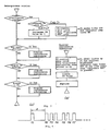
- Fig. 2 is a simplified block diagram depicting the configuration of the electroluminescent panel driving unit.
- a controller system 5 is comprised of a central processing unit (CPU), a read-only memory (ROM), a random access memory (RAM), and a TIMER.
- the ROM stores a variety of system programs.
- a power-generating circuit 7 feeds power to an electroluminescent panel 6 to illuminate the panel surface and thereby supply backlighting for the liquid crystal display unit.
- the luminosity of this electroluminescent panel 6 varies in accordance with the applied AC voltage.
- the electroluminescent panel 6 related to the present invention is provided with four levels of luminosity, about 8.5 V, 6 V, 5 V, and 0 V (when off).
- the power-generating circuit 7 In response to a signal from a digital-analogue (D/A) converter 8, the power-generating circuit 7 applys one of these voltages to the electroluminescent panel 6.
- the desired degree of luminosity can be designated when the data processing device begins operation.
- a 2-bit code is generated in accordance with the luminosity level designated by the operator and latched by a data-latch circuit 9. The 2-bit codes are as follows:
- These 2-bit codes are decoded by a decoder 10 to allow the D/A converter 8 to be activated for proper selection of the voltage level corresponding to the designated 2-bit code.
- the TIMER of the controller system 5 automatically generates a "luminance-OFF" code (00) to turn off the electroluminescent panel 6.
- the decoder 10 outputs the luminance-OFF code (00). As soon as the electroluminescent panel 6 turns off, the luminance-OFF code (00) activates a lamp driver 11 to light up a indicator lamp 3.
- the random access memory contains three operation control registers: a register CS which stores data related to the designated brightness of the electroluminescent panel 6; a register CT which stores data related to the panel-light extinguishing time period that has set; and a register CN which stores data related to the elapsed time.
- the value of the registers CS and CT can be rewritten freely either by key operation performed by the user or by program execution.
- the operation flowchart shown in Fig. 3(a) describes the main process routine, while the operation flowchart shown in Fig. 3(b) denotes the subroutines needed to restore the display.
- the CPU measures the time elapsed by counting the number of timer interruptions generated at specific intervals. (The timer-interruption process is executed as soon as the timer has counted a predetermined time, for example, 1 second, while the system processes the designated data.) Then the controller system sequentially stores the elapsed time into the register CN until the timer has entered the designated time period.
- the controller system compares the value stored in the register CN with the value entered by the operator into the register CT. If the value stored in the register CN is greater than or equal to the value stored in the register CT (CN ⁇ CT), the controller system recognizes that the predetermined time period has elapsed and sets the luminance-OFF code "00" in the data latch circuit 9. This causes the electroluminescent panel 6 illumination to shut off, while the indicator lamp 8 simultaneously lights up.
- the controller system may first clear the value in the register CN and then measure the time during which the entire system is inoperative (the state in which any of the operations is initiated by the user).
- the controller system identifies that the operation has resumed, and causes the electroluminescent panel 6 to restore the original brightness in accordance with the value stored in the register CS. Simultaneously, the controller system clears the value of the register CN to allow the timer to begin counting the elapsed time of inoperation.
- the operator uses the keyboard to check the display contents while the electroluminescent panel 6 is off, the characters on display 2 may be indiscernible or difficult to read. In this case, the operator must restore the panel 6 to its original brightness. No special key is needed to control the data processing device. Any key can be used. This frees the operator from complex follow-up key operations. While the electroluminescent panel 6 remains off, however, the operator cannot easily identify what kind of key-input the controller system is looking for. It is therefore also possible for the operator to void the first key input while the electroluminescent panel 6 remains off and then restore the brightness of the electroluminescent panel 6 to the original level. This allows the operator to correctly identify the contents of the liquid crystal display 2 before normal key-input operation. Fig.
- a pulse “a1” is input by the first strike of a key while the electroluminescent panel 6 is off, which allows the operator to execute the display process described above during period "A.” This lasts until the next "a2" pulse is input by a second strike of a key. The operator then enters data normally through the keyboard by applying pulses "a3","a4", etc. This procedure prevents the operator from incorrectly operating keys when the display contents cannot be seen.
- system operations have been explained based on the assumption that neither key-input, data-output onto the display screen, nor floppy disc accessing operations are executed while the electroluminescent panel 6 remains inoperative.
- the operator's key operation may be taken into account as a trigger.
- the operator can identify whether the data processing device is operative or not by confirming receipt of signals from the voice recognition unit.
- the period of time needed to identify the inoperative state of the electroluminescent panel 6 can be determined properly by the operator in accordance with the conditions of use.
- the data processing device which is provided with a liquid crystal display unit and an electroluminescent backlighting panel reflecting the preferred embodiment of the present invention features means for measuring the inoperative period of the electroluminescent panel and control means for turning off the electroluminescent panel in response to output from the measuring means.
- This allows the controller system to shut off automatically the voltage being fed to the electroluminescent panel after a specific period of time passes, even if the operator leaves the data processing device inoperative by failing to turn off the processor unit power. This effectively limits waste of the electroluminescent panel and ensures a longer service life.
- another preferred embodiment of the present invention provides a novel data processing device which is provided with a liquid crystal display unit having an electroluminescent backlighting panel, and which features the provision of means for measuring the inoperative period of the electroluminescent panel, control means for turning off said electroluminescent panel, and means for informing the operator that the extinguishment of the electroluminescent panel light is due to operation of the control means.
- a novel data processing device which is provided with a liquid crystal display unit having an electroluminescent backlighting panel, and which features the provision of means for measuring the inoperative period of the electroluminescent panel, control means for turning off said electroluminescent panel, and means for informing the operator that the extinguishment of the electroluminescent panel light is due to operation of the control means.
Landscapes
- Engineering & Computer Science (AREA)
- Theoretical Computer Science (AREA)
- Physics & Mathematics (AREA)
- General Physics & Mathematics (AREA)
- General Engineering & Computer Science (AREA)
- Computer Hardware Design (AREA)
- Liquid Crystal Display Device Control (AREA)
- Control Of Indicators Other Than Cathode Ray Tubes (AREA)
- Power Sources (AREA)
Applications Claiming Priority (4)
| Application Number | Priority Date | Filing Date | Title |
|---|---|---|---|
| JP113579/85U | 1985-07-22 | ||
| JP11357985U JPS6222630U (de) | 1985-07-22 | 1985-07-22 | |
| JP1985117724U JPH048405Y2 (de) | 1985-07-29 | 1985-07-29 | |
| JP117724/85U | 1985-07-29 |
Publications (3)
| Publication Number | Publication Date |
|---|---|
| EP0211308A2 true EP0211308A2 (de) | 1987-02-25 |
| EP0211308A3 EP0211308A3 (en) | 1989-06-07 |
| EP0211308B1 EP0211308B1 (de) | 1993-03-17 |
Family
ID=26452523
Family Applications (1)
| Application Number | Title | Priority Date | Filing Date |
|---|---|---|---|
| EP86110005A Expired - Lifetime EP0211308B1 (de) | 1985-07-22 | 1986-07-21 | Datenverarbeitungsanlage |
Country Status (3)
| Country | Link |
|---|---|
| US (1) | US5065357A (de) |
| EP (1) | EP0211308B1 (de) |
| DE (1) | DE3688022T2 (de) |
Cited By (7)
| Publication number | Priority date | Publication date | Assignee | Title |
|---|---|---|---|---|
| EP0496383A3 (en) * | 1991-01-22 | 1993-01-20 | Sony Corporation | Data input and display apparatus |
| EP0443083A3 (en) * | 1990-02-23 | 1993-01-20 | Kabushiki Kaisha Toshiba | Display control apparatus capable of changing luminance depending on conditions of power supply circuit |
| EP0544508A3 (en) * | 1991-11-28 | 1994-11-30 | Shaye Communications Ltd | Illumination of displays |
| EP0651367A1 (de) * | 1993-10-21 | 1995-05-03 | ROHM Co., Ltd. | Anordnung zur Reduzierung der Leistungsaufnahme in einer Matrixanzeige mit Bildveränderungsdetektion |
| EP0661682A1 (de) * | 1993-12-28 | 1995-07-05 | Canon Kabushiki Kaisha | Energiesparsystem für eine Anzeigeeinrichtung mit Bildveränderungsdetektion |
| EP1494202A4 (de) * | 2002-03-27 | 2008-11-12 | Sanyo Electric Co | Anzeigeeinrichtung, mobiles endgerät und luminanzsteuerverfahren in einem mobilen endgerät |
| EP1878378B1 (de) * | 2006-06-29 | 2012-04-18 | Nidek Co., Ltd. | Vorrichtung zur Darstellung von Optotypen |
Families Citing this family (40)
| Publication number | Priority date | Publication date | Assignee | Title |
|---|---|---|---|---|
| JPH039320A (ja) * | 1989-06-06 | 1991-01-17 | Asahi Optical Co Ltd | 液晶表示装置 |
| JP2582644B2 (ja) * | 1989-08-10 | 1997-02-19 | 富士写真フイルム株式会社 | 平面型画像表示装置 |
| US5454112A (en) * | 1990-02-09 | 1995-09-26 | Kabushiki Kaisha Toshiba | Personal computer or the like with a light source controller for a display apparatus |
| US6795929B2 (en) * | 1990-03-23 | 2004-09-21 | Matsushita Electric Industrial Co., Ltd. | Data processing apparatus |
| EP0448350B1 (de) | 1990-03-23 | 1996-12-27 | Matsushita Electric Industrial Co., Ltd. | Hand-Datenverarbeitungsgerät mit reduziertem Leistungsverbrauch |
| JPH0413179A (ja) * | 1990-05-07 | 1992-01-17 | Mitsubishi Electric Corp | 表示制御装置 |
| US5583715A (en) * | 1990-09-03 | 1996-12-10 | Canon Kabushiki Kaisha | Image data communication apparatus |
| JP2949980B2 (ja) * | 1991-12-04 | 1999-09-20 | 富士通株式会社 | 電源制御装置及び情報処理装置 |
| JPH05224783A (ja) * | 1992-02-10 | 1993-09-03 | Brother Ind Ltd | データ処理装置 |
| US5414646A (en) * | 1992-04-16 | 1995-05-09 | Brunson Instrument Company | Digital optical micrometer |
| US5634080A (en) * | 1992-06-29 | 1997-05-27 | Elonex Ip Holdings, Ltd. | Hand-held portable computer having an electroluminescent flat-panel display with pixel elements at right angles to the plane of the display and an excitation direction parallel to the plane of the display |
| US5600800A (en) * | 1992-06-29 | 1997-02-04 | Elonex I.P. Holdings, Ltd. | Personal computer system having a docking bay and a hand-held portable computer adapted to dock in the docking bay by a full-service parallel bus |
| JPH06119090A (ja) * | 1992-10-07 | 1994-04-28 | Hitachi Ltd | 省電力制御方式 |
| US5579489A (en) * | 1993-02-10 | 1996-11-26 | Elonex I.P. Holdings, Ltd. | Hand-held portable computer having capability for external expansion of an internal bus |
| US5615393A (en) * | 1993-03-15 | 1997-03-25 | Elonex I.P. Holdings Ltd. | Computer system having a cordless keyboard and an induction coil in a plug-in electronic card module |
| JPH0744281A (ja) * | 1993-07-29 | 1995-02-14 | Canon Inc | 電力管理装置 |
| KR950010897B1 (ko) * | 1993-08-06 | 1995-09-25 | 삼성전자주식회사 | 컴퓨터 시스템에서 컴퓨터 주변장치의 전원관리신호 발생방법 및 제어장치 |
| WO1996002879A1 (en) * | 1994-07-19 | 1996-02-01 | Elonex Technologies, Inc. | Micro personal digital assistant |
| KR0137917B1 (ko) * | 1994-10-28 | 1998-05-15 | 김광호 | 액정표시소자의 후면광원 구동회로 |
| US5642185A (en) * | 1995-03-07 | 1997-06-24 | Eastman Kodak Company | Automatic termination of screen saver mode on a display of reproduction apparatus |
| US5808597A (en) * | 1995-03-08 | 1998-09-15 | Canon Kabushiki Kaisha | Illumination device for liquid crystal display apparatus |
| KR0148053B1 (ko) * | 1995-05-12 | 1998-09-15 | 김광호 | 액정 표시 소자의 후면 광원 구동 제어 장치 및 그 방법 |
| US6188378B1 (en) * | 1995-06-02 | 2001-02-13 | Canon Kabushiki Kaisha | Display apparatus, display system, and display control method for display system |
| US5944830A (en) * | 1996-03-08 | 1999-08-31 | Samsung Electronics Co., Ltd. | Reducing power consumption in monitor by switching off heater power in power-off mode |
| JPH09282096A (ja) * | 1996-04-16 | 1997-10-31 | Sharp Corp | ペン入力装置 |
| US5894298A (en) | 1997-03-14 | 1999-04-13 | Northern Telecom Limited | Display apparatus |
| US6353893B1 (en) * | 1999-05-24 | 2002-03-05 | Christine Liu | Sleep mode indicator for a battery-operated device |
| JP2001154642A (ja) * | 1999-11-30 | 2001-06-08 | Toshiba Corp | 情報処理装置 |
| US6704004B1 (en) * | 2000-08-17 | 2004-03-09 | Nokia Mobile Phones Ltd. | Arrangement for integration of key illumination into keymat of portable electronic devices |
| JP2002367467A (ja) * | 2001-06-05 | 2002-12-20 | Matsushita Electric Ind Co Ltd | 照光式キーボード装置 |
| US6661410B2 (en) | 2001-09-07 | 2003-12-09 | Microsoft Corporation | Capacitive sensing and data input device power management |
| US6703599B1 (en) * | 2002-01-30 | 2004-03-09 | Microsoft Corporation | Proximity sensor with adaptive threshold |
| US7133028B2 (en) * | 2002-04-23 | 2006-11-07 | Gateway Inc. | Drive activity sampling and notification |
| US20030206256A1 (en) * | 2002-05-06 | 2003-11-06 | Drain Kieran F. | Display device with backlight |
| US6954867B2 (en) * | 2002-07-26 | 2005-10-11 | Microsoft Corporation | Capacitive sensing employing a repeatable offset charge |
| CN100544540C (zh) * | 2004-07-10 | 2009-09-23 | 鸿富锦精密工业(深圳)有限公司 | 灯管寿命延长装置及方法 |
| JP4779995B2 (ja) * | 2007-02-28 | 2011-09-28 | ソニー株式会社 | 画像表示装置及び電子機器 |
| KR101387404B1 (ko) * | 2007-08-30 | 2014-04-21 | 삼성전자주식회사 | 디지털 영상 처리장치의 제어장치 및 그 방법 |
| KR102255456B1 (ko) * | 2014-11-07 | 2021-05-24 | 삼성전자주식회사 | 화면 제어 방법 및 장치 |
| KR102336183B1 (ko) * | 2015-02-23 | 2021-12-07 | 삼성전자 주식회사 | 전자 장치 및 이를 위한 저전력 구동 방법 |
Family Cites Families (7)
| Publication number | Priority date | Publication date | Assignee | Title |
|---|---|---|---|---|
| JPS4841126U (de) * | 1971-09-17 | 1973-05-25 | ||
| US3736569A (en) * | 1971-10-13 | 1973-05-29 | Ibm | System for controlling power consumption in a computer |
| US4381552A (en) * | 1978-12-08 | 1983-04-26 | Motorola Inc. | Stanby mode controller utilizing microprocessor |
| US4365290A (en) * | 1979-03-12 | 1982-12-21 | Medtronic, Inc. | Computer system with power control circuit |
| US4293927A (en) * | 1979-12-12 | 1981-10-06 | Casio Computer Co., Ltd. | Power consumption control system for electronic digital data processing devices |
| DE2951162A1 (de) * | 1979-12-19 | 1981-07-02 | Casio Computer Co., Ltd., Tokyo | Vorrichtung zum steuern des energieverbrauchs fuer eine elektronische digitale datenverarbeitungsvorrichtung |
| JPS58142686A (ja) * | 1982-02-18 | 1983-08-24 | Casio Comput Co Ltd | 液晶テレビジヨン受像機 |
-
1986
- 1986-07-21 DE DE86110005T patent/DE3688022T2/de not_active Expired - Fee Related
- 1986-07-21 EP EP86110005A patent/EP0211308B1/de not_active Expired - Lifetime
-
1990
- 1990-08-09 US US07/565,179 patent/US5065357A/en not_active Expired - Fee Related
Cited By (11)
| Publication number | Priority date | Publication date | Assignee | Title |
|---|---|---|---|---|
| EP0443083A3 (en) * | 1990-02-23 | 1993-01-20 | Kabushiki Kaisha Toshiba | Display control apparatus capable of changing luminance depending on conditions of power supply circuit |
| US5386577A (en) * | 1990-02-23 | 1995-01-31 | Kabushiki Kaisha Toshiba | Display control apparatus capable of changing luminance depending on conditions of power supply circuit |
| US5493685A (en) * | 1990-02-23 | 1996-02-20 | Kabushiki Kaisha Toshiba | Display control apparatus capable of changing luminance depending on conditions of power supply circuit |
| EP0496383A3 (en) * | 1991-01-22 | 1993-01-20 | Sony Corporation | Data input and display apparatus |
| EP0544508A3 (en) * | 1991-11-28 | 1994-11-30 | Shaye Communications Ltd | Illumination of displays |
| EP0651367A1 (de) * | 1993-10-21 | 1995-05-03 | ROHM Co., Ltd. | Anordnung zur Reduzierung der Leistungsaufnahme in einer Matrixanzeige mit Bildveränderungsdetektion |
| US5828367A (en) * | 1993-10-21 | 1998-10-27 | Rohm Co., Ltd. | Display arrangement |
| EP0661682A1 (de) * | 1993-12-28 | 1995-07-05 | Canon Kabushiki Kaisha | Energiesparsystem für eine Anzeigeeinrichtung mit Bildveränderungsdetektion |
| US6005559A (en) * | 1993-12-28 | 1999-12-21 | Canon Kabushiki Kaisha | Display apparatus with a power conserving display |
| EP1494202A4 (de) * | 2002-03-27 | 2008-11-12 | Sanyo Electric Co | Anzeigeeinrichtung, mobiles endgerät und luminanzsteuerverfahren in einem mobilen endgerät |
| EP1878378B1 (de) * | 2006-06-29 | 2012-04-18 | Nidek Co., Ltd. | Vorrichtung zur Darstellung von Optotypen |
Also Published As
| Publication number | Publication date |
|---|---|
| EP0211308B1 (de) | 1993-03-17 |
| DE3688022D1 (de) | 1993-04-22 |
| EP0211308A3 (en) | 1989-06-07 |
| DE3688022T2 (de) | 1993-09-30 |
| US5065357A (en) | 1991-11-12 |
Similar Documents
| Publication | Publication Date | Title |
|---|---|---|
| EP0211308A2 (de) | Datenverarbeitungsanlage | |
| KR100626359B1 (ko) | 컴퓨터 시스템의 전원 관리 방법 | |
| US20110213262A1 (en) | Method for Presenting Current and Stored ECG Waveforms on a Portable, External Defibrillator | |
| KR910006834A (ko) | 전원회로의 제조건에 의해 휘도를 변경시킬수 있는 디스플레이 제어장치 | |
| EP0430219A2 (de) | Verfahren und System zum Wiederaufnahmesteuerungsprozess in einer Rechnereinheit, die eine Erweiterungseinheit verbinden kann | |
| EP0404182A1 (de) | Personalcomputer zum Einstellen von normaler oder inverser Anzeige, externer Geräte und automatischer Bildschirmabschaltung beim Einstellvorgang | |
| JPH0619444A (ja) | 情報処理装置 | |
| JPH048405Y2 (de) | ||
| KR19990033133A (ko) | 컴퓨터 시스템의 리얼타임클럭 진단방법 및 그장치 | |
| JPH10268981A (ja) | コンピュータシステムの電源遮断装置及び方法 | |
| JP3122605B2 (ja) | 電子機器 | |
| KR100584624B1 (ko) | 컴퓨터에서의 시스템 상태 표시장치 및 방법 | |
| JPH04303594A (ja) | インバータ制御システム | |
| JPH0736574A (ja) | 電子機器の初期化装置及び方法 | |
| JPH06337772A (ja) | 画像データ表示装置 | |
| KR910001307Y1 (ko) | 개인용 콤퓨터의 하드디스크 사용상태 표시장치 | |
| JPH10206195A (ja) | 記録計 | |
| JPH08313905A (ja) | 液晶ディスプレイ装置 | |
| JP3320308B2 (ja) | 節電モードを備えた情報処理装置 | |
| JPS644195B2 (de) | ||
| KR100601616B1 (ko) | 기능키에 의해 사용자 감지기능을 제어하는 컴퓨터 및 그 방법 | |
| JPH07294877A (ja) | 表示バックライト制御装置 | |
| KR100312043B1 (ko) | 전자식 금전 등록기의 자동 리셋트 방법 및 그 장치 | |
| JP2827237B2 (ja) | 電子機器テスト回路 | |
| JPH0731344Y2 (ja) | 表示切換装置 |
Legal Events
| Date | Code | Title | Description |
|---|---|---|---|
| PUAI | Public reference made under article 153(3) epc to a published international application that has entered the european phase |
Free format text: ORIGINAL CODE: 0009012 |
|
| 17P | Request for examination filed |
Effective date: 19860721 |
|
| AK | Designated contracting states |
Kind code of ref document: A2 Designated state(s): DE FR GB |
|
| PUAL | Search report despatched |
Free format text: ORIGINAL CODE: 0009013 |
|
| AK | Designated contracting states |
Kind code of ref document: A3 Designated state(s): DE FR GB |
|
| 17Q | First examination report despatched |
Effective date: 19910724 |
|
| GRAA | (expected) grant |
Free format text: ORIGINAL CODE: 0009210 |
|
| AK | Designated contracting states |
Kind code of ref document: B1 Designated state(s): DE FR GB |
|
| REF | Corresponds to: |
Ref document number: 3688022 Country of ref document: DE Date of ref document: 19930422 |
|
| ET | Fr: translation filed | ||
| PLBE | No opposition filed within time limit |
Free format text: ORIGINAL CODE: 0009261 |
|
| STAA | Information on the status of an ep patent application or granted ep patent |
Free format text: STATUS: NO OPPOSITION FILED WITHIN TIME LIMIT |
|
| 26N | No opposition filed | ||
| PGFP | Annual fee paid to national office [announced via postgrant information from national office to epo] |
Ref country code: FR Payment date: 20010712 Year of fee payment: 16 |
|
| PGFP | Annual fee paid to national office [announced via postgrant information from national office to epo] |
Ref country code: DE Payment date: 20010716 Year of fee payment: 16 |
|
| PGFP | Annual fee paid to national office [announced via postgrant information from national office to epo] |
Ref country code: GB Payment date: 20010718 Year of fee payment: 16 |
|
| REG | Reference to a national code |
Ref country code: GB Ref legal event code: IF02 |
|
| PG25 | Lapsed in a contracting state [announced via postgrant information from national office to epo] |
Ref country code: GB Free format text: LAPSE BECAUSE OF NON-PAYMENT OF DUE FEES Effective date: 20020721 |
|
| PG25 | Lapsed in a contracting state [announced via postgrant information from national office to epo] |
Ref country code: DE Free format text: LAPSE BECAUSE OF NON-PAYMENT OF DUE FEES Effective date: 20030201 |
|
| GBPC | Gb: european patent ceased through non-payment of renewal fee |
Effective date: 20020721 |
|
| PG25 | Lapsed in a contracting state [announced via postgrant information from national office to epo] |
Ref country code: FR Free format text: LAPSE BECAUSE OF NON-PAYMENT OF DUE FEES Effective date: 20030331 |
|
| REG | Reference to a national code |
Ref country code: FR Ref legal event code: ST |