EP0211445A1 - Zusammensetzung eines magnetoresistiven Lesewandlers - Google Patents
Zusammensetzung eines magnetoresistiven Lesewandlers Download PDFInfo
- Publication number
- EP0211445A1 EP0211445A1 EP86110983A EP86110983A EP0211445A1 EP 0211445 A1 EP0211445 A1 EP 0211445A1 EP 86110983 A EP86110983 A EP 86110983A EP 86110983 A EP86110983 A EP 86110983A EP 0211445 A1 EP0211445 A1 EP 0211445A1
- Authority
- EP
- European Patent Office
- Prior art keywords
- bias
- sensor
- extensions
- assembly
- edge
- Prior art date
- Legal status (The legal status is an assumption and is not a legal conclusion. Google has not performed a legal analysis and makes no representation as to the accuracy of the status listed.)
- Granted
Links
Images


Classifications
-
- G—PHYSICS
- G11—INFORMATION STORAGE
- G11B—INFORMATION STORAGE BASED ON RELATIVE MOVEMENT BETWEEN RECORD CARRIER AND TRANSDUCER
- G11B5/00—Recording by magnetisation or demagnetisation of a record carrier; Reproducing by magnetic means; Record carriers therefor
- G11B5/127—Structure or manufacture of heads, e.g. inductive
- G11B5/33—Structure or manufacture of flux-sensitive heads, i.e. for reproduction only; Combination of such heads with means for recording or erasing only
- G11B5/39—Structure or manufacture of flux-sensitive heads, i.e. for reproduction only; Combination of such heads with means for recording or erasing only using magneto-resistive devices or effects
- G11B5/3903—Structure or manufacture of flux-sensitive heads, i.e. for reproduction only; Combination of such heads with means for recording or erasing only using magneto-resistive devices or effects using magnetic thin film layers or their effects, the films being part of integrated structures
Definitions
- This invention relates to a magnetoresistive read transducer assembly for reading data from a magnetic record medium.
- a known magnetoresistive (MR) sensor or head is capable of reading data from a magnetic surface at great linear densities.
- the MR sensor operates on the principle that the resistance of the read element is a function of the amount and direction of magnetic flux being sensed by the element.
- the prior art also teaches that in order for an MR element to operate optimally, two bias fields should be provided, a first bias field along its transverse direction as well as a second bias field along its longitudinal direction.
- the transverse bias orients the magnetisation at some skew angle relative to the sense current, as is necessary to obtain a linear component of response to the flux field in the otherwise quadratic response.
- This bias field is normal to the plane of the magnetic media and parallel to the surface of the planar MR element.
- the longitudinal bias has the purpose of inducing a single domain state of magnetisation, as is required for the suppression of Barkhausen noise.
- the longitudinal bias field extends parallel to the surface of the magnetic media and parallel to the lengthwise direction of the MR sensor.
- bias method is current deflection bias, as shown in US-A-4,280,158.
- the quiescent magnetisation remains along the longitudinal direction, while, instead, the sense current is deflected to flow askew to the magnetisation. This effect is achieved with a superpositioned 'barberpole' conductor configuration.
- This method produces a transverse bias condition along with a small (typically insufficient) longitudinal bias field underneath the conductor.
- a further type of prior method of bias comprises permanent magnet bias in which the bias condition is produced with a proximate hard magnetic film.
- the hard magnetic film may be ferromagnetic and coupled magnetostatically to the sensor as described in US-A-3,840,898.
- the film may be antiferromagnetic and coupled to the sensor via an exchange mechanism as described in US-A-4,103,315. Either method can, at least in principle, provide a transverse and/or a longitudinal bias component.
- US-A-4,418,372 discloses a magnetic rotary encoder comprising a substrate having a surface opposite to a rotary body having plural pieces of magnetic information recorded on at least one circumferentially running track.
- the substrate has a magnetoresistive element formed on its surface having a pattern including at least two portions extending in the radial direction of the rotary body and connected at the ends by a circumferentially extending portion.
- the disclosed arrangement is not designed to produce a bias in the MR element, but to produce an additive signal from each of the portions in the radial direction and phasing produced by the circumferential portions.
- This invention seeks to provide an improved biased magnetoresistive read transducer assembly.
- a magnetoresistive read transducer assembly including a magnetoresistive element having one edge which, in use, faces a record medium is according to the invention characterised by having a plurality of elongate extensions of the same material as the element, extending from at least one of the other edges of the element, the elongate extensions being unidirectionally magnetised along their length in order to provide bias for the element.
- a plurality of elongate extensions extend parallel to the edge of the MR element which is adapted to face the magnetic medium and a plurality of elongate extensions extend in the direction normal to the edge of the MR element which is away from the magnetic medium.
- an exchange bias film patterned to the same geometry as the MR element, and the MR element are sandwiched together.
- the resultant combined bias improves the bias profile.
- Figure 1(a) is a sketch showing the quiescent magnetisation, M, at some skew angle relative to the sense current, I, through the MR sensor 10.
- FIG. 1(d) The sketch of Figure 1(d) shows that the excitation, originating from magnetic charges in the medium 11, is largest at the lower edge of the MR sensor 10. On moving up on the sensor stripe, the flux leaks to the adjacent shields 12, and excitation decreases. As shown in Figure 1(e) typically, the excitation is not a 'small signal input' but, at least at the lower stripe edge, causes excursions over a substantial portion of the sensor's operating range. The excitation vanishes at the upper edge, h.
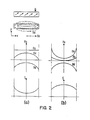
- Figure 2 illustrates relationships helpful in understanding the desired longitudinal bias profile.
- the longitudinal bias must be strong enough to retain the sensor in a single domain state, as is required for the suppression of Barkhausen noise.
- Hx the lower the sensitivity of the MR sensor.
- the applied longitudinal bias field, Ha is uniform, as indicated in Figure 2(a), so that the effective bias field, He, being the sum of the applied and the demagnetising field, Hd, peaks about the centre of the sensor.
- the resulting concave sensitivity profile, S is undesirable since the magnetic head would have a sensitivity that is lowest over the centre of the track and highest about the edges of the track.
- a more advantageous convex sensitivity profile, Figure 2(b) is attainable with a bias field that increases in strength toward the ends of the sensor. Such bias renders the sensor single domain, while leaving its centre segment at maximum sensitivity.
- the present invention involves the addition of elongate or 'comb' extensions 14 to the MR sensor 10 as shown in Figure 3.
- An elongate vertical comb extension 14v as shown in Figure 3(a), provides transverse bias while the elongate horizontal extensions or comb 14H of Figure 3(b) provides longitudinal bias.
- Both bias components are obtained from a configuration like the one shown in Figure 3(c) in which both horizontal combs 14h and vertical combs 14v are provided on the same MR sensor 10.
- the combs 14 are contiguous with and made of the same material as the MR sensor element 10.
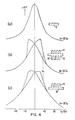
- Figure 4 shows the effects of transverse extensions. These MR characteristic curves were measured versus a varying transverse field, Hy, plus a constant longitudinal field, Hx, to retain a single domain magnetisation. The three curves show plots of ⁇ R/R vs Hx for different sensor geometries.
- Curve (a) shows the response of a 25 ⁇ m wide stripe without extensions (as a reference).
- Curve (b) shows the response of an MR stripe with transverse extensions on both sides
- curve (c) shows the response of an MR stripe with transverse extensions on only one side.
- test data on specific embodiments of the comb MR structure has shown that this structure is capable of providing a self-sufficient bias.
- the question of whether the bias is self-sufficient involves two issues, bias permeance and the level of bias that can be achieved.
- Bias permeance requires the reversal threshold Ht to be larger than any disturbing fields seen by the comb structure.
- the disturbing fields may be environmental or originate from the storage medium. Whatever their external value, the strength of such fields will be much reduced at the comb location, at least within the usual MR configuration employing magnetic shields as shown in Figure 6.
- the amplitude of this residual disturbance has to be compared with the reversal threshold for Ht.
- one specific embodiment similar to Figure 5 has 2.4 ⁇ m wide extensions and a reversal threshold of about 30 0e.
- Narrower extensions 1.4 ⁇ m wide, have a reversal threshold of about 50 0e. Although these values appear safe relative to the expected amplitudes of disturbing fields, there remains the concern that repetitive disturbance cycles may degrade the bias condition in some fashion. Testing was done regarding the possibility of such an occurrence, and no degradation of bias was found after 30,000 disturbance cycles, even with disturbance amplitudes just below Ht.
- bias permeance and sufficiency are hence dictated by geometry and limited by resolution of the fabrication process. Bias permeance improves with a decreasing width of the extensions, while bias sufficiency improves with an increasing width/spacing ratio. These competing requirements can both be satisfied only by having small spacings between extensions.
- the MR sensor has a geometry such as that shown in Figure 3(c), and a section view of this sensor is shown in Figure 6.
- a plurality of horizontal combs 14h and a plurality of vertical combs are provided on the same MR sensor 10, and electrical conductor leads 16 (shown in dashed line in Figure 3(c)) are provided to conduct the read signal to the external read circuits (not shown).
- the MR sensor 10 is preferably flanked by soft-magnetic shields 12, but in some cases the shields can be omitted.
- the MR sensor was fabricated having the geometry of Figures 3(c) and Figure 6 and having the following dimensions, and this sensor had suitable performance characteristics.
- the sensor has an MR stripe height of 10 ⁇ m, and comb extensions that are 50 ⁇ m long, and 2.5 ⁇ m, wide with a spacing between comb extensions of 1 ⁇ m.
- the comb configuration need not necessarily be used as a self-sufficient bias method. It can also, at no expense, be used to improve upon some other bias provisions. There is no reason, in principle, why the comb configuration can be used to enhance any of the bias techniques discussed in the prior art section of this application. For example, it may be used in combination with exchange bias.
- the sensor consists of a sandwiched MR sensor 10 and exchange bias film 16, both patterned together to the same geometry such as that shown in Figure 3(a), for example.
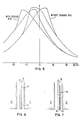
- Figure 5 compares response characteristics of two identical comb configurations, one with and one without exchange bias. Without exchange bias, as shown in curve (a) we have the familiar transverse response, indicating an average, comb-induced bias field of 15 0e.
- exchange bias which, in effect, acts just like a superpositioned DC magnetic field
- the loop is offset relative to Hy.
- the amount of offset equals the transverse component of exchange bias.
- the direction of exchange bias is adjustable, one can adjust relative bias components in the transverse and the longitudinal direction. In the present example, the bias direction was set at 85 degrees from the x-axis. The curve shows a resulting transverse bias of 32 0e and one would hence estimate a 3 0e longitudinal component.
Landscapes
- Engineering & Computer Science (AREA)
- Manufacturing & Machinery (AREA)
- Measuring Magnetic Variables (AREA)
- Magnetic Heads (AREA)
Applications Claiming Priority (2)
| Application Number | Priority Date | Filing Date | Title |
|---|---|---|---|
| US765999 | 1985-08-15 | ||
| US06/765,999 US4649447A (en) | 1985-08-15 | 1985-08-15 | Combed MR sensor |
Publications (2)
| Publication Number | Publication Date |
|---|---|
| EP0211445A1 true EP0211445A1 (de) | 1987-02-25 |
| EP0211445B1 EP0211445B1 (de) | 1990-07-25 |
Family
ID=25075101
Family Applications (1)
| Application Number | Title | Priority Date | Filing Date |
|---|---|---|---|
| EP86110983A Expired EP0211445B1 (de) | 1985-08-15 | 1986-08-08 | Zusammensetzung eines magnetoresistiven Lesewandlers |
Country Status (4)
| Country | Link |
|---|---|
| US (1) | US4649447A (de) |
| EP (1) | EP0211445B1 (de) |
| JP (1) | JPS6240611A (de) |
| DE (1) | DE3672919D1 (de) |
Cited By (2)
| Publication number | Priority date | Publication date | Assignee | Title |
|---|---|---|---|---|
| WO1990007774A1 (en) * | 1989-01-03 | 1990-07-12 | Eastman Kodak Company | Deposited permanent magnet for hard and easy axes biasing of a magnetoresistive head |
| EP0656621A3 (de) * | 1993-12-03 | 1996-07-31 | Eastman Kodak Co | Magnetoresistiver Kopf mit abgeschiedenem Vormagnetisierungsmagnet. |
Families Citing this family (24)
| Publication number | Priority date | Publication date | Assignee | Title |
|---|---|---|---|---|
| DE3644388A1 (de) * | 1985-12-27 | 1987-07-02 | Sharp Kk | Duennfilm-joch-magnetkopf |
| US4771349A (en) * | 1986-10-31 | 1988-09-13 | International Business Machine Corporation | Magnetoresistive read transducer |
| US5159511A (en) * | 1987-04-01 | 1992-10-27 | Digital Equipment Corporation | Biasing conductor for MR head |
| US5081554A (en) * | 1987-04-01 | 1992-01-14 | Digital Equipment Corporation | Biasing conductor for MR head |
| US4954803A (en) * | 1988-03-18 | 1990-09-04 | Yamaha Corporation | Magnetic-resistor sensor and a magnetic encoder using such a sensor |
| US5089334A (en) * | 1988-08-03 | 1992-02-18 | Digital Equipment Corporation | Flux spreading thin film magnetic devices |
| US5085935A (en) * | 1988-08-03 | 1992-02-04 | Digital Equipment Corporation | Flux spreading thin film magnetic devices |
| CA1334447C (en) * | 1988-08-03 | 1995-02-14 | Digital Equipment Corporation | Perpendicular anisotropy in thin film devices |
| US5125408A (en) * | 1988-10-24 | 1992-06-30 | The United States Of America As Represented By The Of The Department Of Health And Human Services | Pressure sensor element and method to measure contact stress |
| US5184267A (en) * | 1989-06-02 | 1993-02-02 | Digital Equipment Corporation | Transducer with improved inductive coupling |
| US5195005A (en) * | 1989-06-02 | 1993-03-16 | Digital Equipment Corporation | Tranducer with improved inductive coupling |
| US5428893A (en) * | 1989-06-02 | 1995-07-04 | Quantum Corporation | Method of making a transducer with improved inductive coupling |
| US5311386A (en) * | 1989-06-02 | 1994-05-10 | Digital Equipment Corporation | Transducer with improved inductive coupling |
| US5155642A (en) * | 1989-11-29 | 1992-10-13 | International Business Machines Corporation | Anisotropy configuration for longitudinally constrained magnetoresistive transducers |
| US5168395A (en) * | 1990-05-02 | 1992-12-01 | International Business Machines Corporation | Controlled magnetic recording head relaxation in a magnetic recording system |
| US5293031A (en) * | 1991-03-18 | 1994-03-08 | Atsutoshi Goto | Magnetic bar code reading system employing phase-shift type sensor having plural sensing sections |
| US5331496A (en) * | 1992-02-14 | 1994-07-19 | Digital Equipment Corporation | Thin-film magnetic transducer with a multitude of magnetic flux interactions |
| US5479308A (en) * | 1993-11-15 | 1995-12-26 | Voegeli; Otto | Magnetoresistive transducer including interdiffusion layer |
| FR2713782B1 (fr) * | 1993-12-14 | 1996-01-05 | Thomson Csf | Capteur magnétique à effet magnéto-résistif. |
| TW349690U (en) * | 1994-12-16 | 1999-01-01 | Ibm | Magnetoresistive head with a magnetoresistive film shaped to provide an improved read sensitivity profile |
| US6600636B1 (en) | 1999-10-12 | 2003-07-29 | Maxtor Corporation | Magnetic head with write element offset from read element |
| GB0423676D0 (en) * | 2004-10-25 | 2004-11-24 | Arjo Wiggins Ltd | Method for reading magnetic data |
| US7545602B1 (en) * | 2005-07-26 | 2009-06-09 | Sun Microsystems, Inc. | Use of grating structures to control asymmetry in a magnetic sensor |
| JP5949672B2 (ja) * | 2013-06-10 | 2016-07-13 | 日立金属株式会社 | 検出装置、及び検出装置の製造方法 |
Citations (5)
| Publication number | Priority date | Publication date | Assignee | Title |
|---|---|---|---|---|
| AT351795B (de) * | 1975-12-29 | 1979-08-10 | Sony Corp | Magnetfeld-messfuehler zur erzeugung eines aus- gangssignals |
| DE3118850A1 (de) * | 1981-05-12 | 1982-12-02 | Siemens AG, 1000 Berlin und 8000 München | Verfahren zum herstellen eines substrats mit im konstanten abstand von einer substratkante aufgebrachten, geradlinig begrenzten strukturen und anordnung zur durchfuehrung des verfahrens |
| DE3311242A1 (de) * | 1982-03-29 | 1983-11-17 | Nippon Electric Co., Ltd., Tokyo | Magnetoresistiver kopf |
| DE3339037A1 (de) * | 1982-10-28 | 1984-05-03 | Sony Corp., Tokio/Tokyo | Magnetischer mehrkanal-wandlerkopf |
| EP0124293A2 (de) * | 1983-04-04 | 1984-11-07 | Hewlett-Packard Company | Dünnschichtwandler für induktive Aufzeichnung und magnetoresistive Wiedergabe |
Family Cites Families (16)
| Publication number | Priority date | Publication date | Assignee | Title |
|---|---|---|---|---|
| US3731007A (en) * | 1971-04-19 | 1973-05-01 | Denki Onkyo Co Ltd | Magnetic head having a magneto-resistive bridge circuit |
| GB1411629A (en) * | 1971-12-14 | 1975-10-29 | Matsushita Electric Industrial Co Ltd | Magnetic recording head and manufacture thereof |
| US3813692A (en) * | 1972-10-11 | 1974-05-28 | Ibm | Internally biased magnetoresistive magnetic transducer |
| US3840898A (en) * | 1972-12-29 | 1974-10-08 | Ibm | Self-biased magnetoresistive sensor |
| US3864751A (en) * | 1973-10-04 | 1975-02-04 | Ibm | Induced bias magnetoresistive read transducer |
| US4047236A (en) * | 1975-05-09 | 1977-09-06 | Honeywell Information Systems Inc. | Supersensitive magnetoresistive sensor for high density magnetic read head |
| US4300177A (en) * | 1975-07-17 | 1981-11-10 | U.S. Philips Corporation | Thin-film magnetic head for reading and writing information |
| US4103315A (en) * | 1977-06-24 | 1978-07-25 | International Business Machines Corporation | Antiferromagnetic-ferromagnetic exchange bias films |
| NL7806568A (nl) * | 1978-06-19 | 1979-12-21 | Philips Nv | Magnetoweerstand leeskop. |
| JPS5597021A (en) * | 1979-01-16 | 1980-07-23 | Matsushita Electric Ind Co Ltd | Thin-film magnetic head and its manufacture |
| US4418372A (en) * | 1979-08-02 | 1983-11-29 | Hitachi, Ltd. | Magnetic rotary encoder |
| JPS6032885B2 (ja) * | 1980-03-26 | 1985-07-31 | 松下電器産業株式会社 | 薄膜磁気ヘッド |
| US4343026A (en) * | 1980-07-09 | 1982-08-03 | Spin Physics, Inc. | Magnetoresistive head employing field feedback |
| US4477794A (en) * | 1981-08-10 | 1984-10-16 | Matsushita Electric Industrial Co., Ltd. | Magnetoresistive element |
| JPS5845619A (ja) * | 1981-09-09 | 1983-03-16 | Hitachi Ltd | 磁気抵抗効果型薄膜磁気ヘッド |
| JPS5936320A (ja) * | 1982-08-24 | 1984-02-28 | Canon Inc | 磁気抵抗効果型磁気ヘツド |
-
1985
- 1985-08-15 US US06/765,999 patent/US4649447A/en not_active Expired - Lifetime
-
1986
- 1986-07-11 JP JP61162211A patent/JPS6240611A/ja active Pending
- 1986-08-08 EP EP86110983A patent/EP0211445B1/de not_active Expired
- 1986-08-08 DE DE8686110983T patent/DE3672919D1/de not_active Expired - Lifetime
Patent Citations (5)
| Publication number | Priority date | Publication date | Assignee | Title |
|---|---|---|---|---|
| AT351795B (de) * | 1975-12-29 | 1979-08-10 | Sony Corp | Magnetfeld-messfuehler zur erzeugung eines aus- gangssignals |
| DE3118850A1 (de) * | 1981-05-12 | 1982-12-02 | Siemens AG, 1000 Berlin und 8000 München | Verfahren zum herstellen eines substrats mit im konstanten abstand von einer substratkante aufgebrachten, geradlinig begrenzten strukturen und anordnung zur durchfuehrung des verfahrens |
| DE3311242A1 (de) * | 1982-03-29 | 1983-11-17 | Nippon Electric Co., Ltd., Tokyo | Magnetoresistiver kopf |
| DE3339037A1 (de) * | 1982-10-28 | 1984-05-03 | Sony Corp., Tokio/Tokyo | Magnetischer mehrkanal-wandlerkopf |
| EP0124293A2 (de) * | 1983-04-04 | 1984-11-07 | Hewlett-Packard Company | Dünnschichtwandler für induktive Aufzeichnung und magnetoresistive Wiedergabe |
Cited By (2)
| Publication number | Priority date | Publication date | Assignee | Title |
|---|---|---|---|---|
| WO1990007774A1 (en) * | 1989-01-03 | 1990-07-12 | Eastman Kodak Company | Deposited permanent magnet for hard and easy axes biasing of a magnetoresistive head |
| EP0656621A3 (de) * | 1993-12-03 | 1996-07-31 | Eastman Kodak Co | Magnetoresistiver Kopf mit abgeschiedenem Vormagnetisierungsmagnet. |
Also Published As
| Publication number | Publication date |
|---|---|
| JPS6240611A (ja) | 1987-02-21 |
| DE3672919D1 (de) | 1990-08-30 |
| US4649447A (en) | 1987-03-10 |
| EP0211445B1 (de) | 1990-07-25 |
Similar Documents
| Publication | Publication Date | Title |
|---|---|---|
| EP0211445B1 (de) | Zusammensetzung eines magnetoresistiven Lesewandlers | |
| US5084794A (en) | Shorted dual element magnetoresistive reproduce head exhibiting high density signal amplification | |
| US4803580A (en) | Double-gap magnetoresistive head having an elongated central write/shield pole completely shielding the magnetoresistive sensor strip in the read gap | |
| CN1008668B (zh) | 磁阻读出传感器 | |
| US4967298A (en) | Magnetic head with magnetoresistive sensor, inductive write head, and shield | |
| US5731937A (en) | Giant magnetoresistive transducer with increased output signal | |
| US4891725A (en) | Magnetoresistive sensor having antiferromagnetic exchange-biased ends | |
| JPH0439738B2 (de) | ||
| US6456068B1 (en) | Magnetic impedance element having a highly linear magnetic field detection range | |
| EP0279537B1 (de) | Magnetoresistiver Sensor und Verfahren zu seiner Herstellung | |
| KR100561288B1 (ko) | 자기 검출 장치 | |
| CN1122497A (zh) | 峰值增强的磁致电阻读传感器 | |
| EP0265798A2 (de) | Magnetoresistiver Lesewandler | |
| EP0553434B1 (de) | Dünnfilmmagnetkopf | |
| JPS638531B2 (de) | ||
| KR100196654B1 (ko) | 자기신호 검출장치 | |
| JPH0618278A (ja) | 磁気センサ | |
| JPH0375925B2 (de) | ||
| EP0430672A2 (de) | Magnetoresistiver Wandler | |
| Tsang et al. | Study of recessed MR sensors with unlaminated and multi-laminated flux-guides | |
| JPH08201492A (ja) | 磁気センサ | |
| JPH0473316B2 (de) | ||
| Tsang | A theoretical study of the signal response of a shielded MR sensor (magnetic heads) | |
| US6154350A (en) | Soft adjacent layer-biased magnetoresistive head and method | |
| JP3123276B2 (ja) | 位置検出装置 |
Legal Events
| Date | Code | Title | Description |
|---|---|---|---|
| PUAI | Public reference made under article 153(3) epc to a published international application that has entered the european phase |
Free format text: ORIGINAL CODE: 0009012 |
|
| AK | Designated contracting states |
Kind code of ref document: A1 Designated state(s): DE FR GB |
|
| 17P | Request for examination filed |
Effective date: 19870623 |
|
| 17Q | First examination report despatched |
Effective date: 19890315 |
|
| GRAA | (expected) grant |
Free format text: ORIGINAL CODE: 0009210 |
|
| AK | Designated contracting states |
Kind code of ref document: B1 Designated state(s): DE FR GB |
|
| REF | Corresponds to: |
Ref document number: 3672919 Country of ref document: DE Date of ref document: 19900830 |
|
| ET | Fr: translation filed | ||
| PLBE | No opposition filed within time limit |
Free format text: ORIGINAL CODE: 0009261 |
|
| STAA | Information on the status of an ep patent application or granted ep patent |
Free format text: STATUS: NO OPPOSITION FILED WITHIN TIME LIMIT |
|
| 26N | No opposition filed | ||
| PGFP | Annual fee paid to national office [announced via postgrant information from national office to epo] |
Ref country code: GB Payment date: 19960724 Year of fee payment: 11 |
|
| PGFP | Annual fee paid to national office [announced via postgrant information from national office to epo] |
Ref country code: FR Payment date: 19960806 Year of fee payment: 11 |
|
| PGFP | Annual fee paid to national office [announced via postgrant information from national office to epo] |
Ref country code: DE Payment date: 19960828 Year of fee payment: 11 |
|
| PG25 | Lapsed in a contracting state [announced via postgrant information from national office to epo] |
Ref country code: GB Free format text: LAPSE BECAUSE OF NON-PAYMENT OF DUE FEES Effective date: 19970808 |
|
| GBPC | Gb: european patent ceased through non-payment of renewal fee |
Effective date: 19970808 |
|
| PG25 | Lapsed in a contracting state [announced via postgrant information from national office to epo] |
Ref country code: FR Free format text: LAPSE BECAUSE OF NON-PAYMENT OF DUE FEES Effective date: 19980430 |
|
| PG25 | Lapsed in a contracting state [announced via postgrant information from national office to epo] |
Ref country code: DE Free format text: LAPSE BECAUSE OF NON-PAYMENT OF DUE FEES Effective date: 19980501 |
|
| REG | Reference to a national code |
Ref country code: FR Ref legal event code: ST |