EP0211547B1 - Broyage de matériau - Google Patents
Broyage de matériau Download PDFInfo
- Publication number
- EP0211547B1 EP0211547B1 EP86305507A EP86305507A EP0211547B1 EP 0211547 B1 EP0211547 B1 EP 0211547B1 EP 86305507 A EP86305507 A EP 86305507A EP 86305507 A EP86305507 A EP 86305507A EP 0211547 B1 EP0211547 B1 EP 0211547B1
- Authority
- EP
- European Patent Office
- Prior art keywords
- gas
- chamber
- surface active
- pressure
- grinding
- Prior art date
- Legal status (The legal status is an assumption and is not a legal conclusion. Google has not performed a legal analysis and makes no representation as to the accuracy of the status listed.)
- Expired - Lifetime
Links
- 239000000463 material Substances 0.000 title claims abstract description 74
- 238000000034 method Methods 0.000 claims abstract description 34
- 239000004094 surface-active agent Substances 0.000 claims abstract description 25
- 238000000227 grinding Methods 0.000 claims description 85
- 239000002585 base Substances 0.000 claims description 15
- 125000000217 alkyl group Chemical group 0.000 claims description 8
- -1 phosphate ester Chemical class 0.000 claims description 7
- 229910052783 alkali metal Inorganic materials 0.000 claims description 6
- 125000004432 carbon atom Chemical group C* 0.000 claims description 6
- 229920001577 copolymer Polymers 0.000 claims description 5
- 230000007423 decrease Effects 0.000 claims description 5
- 150000001340 alkali metals Chemical class 0.000 claims description 4
- 150000003863 ammonium salts Chemical class 0.000 claims description 4
- 150000003839 salts Chemical class 0.000 claims description 4
- KDYFGRWQOYBRFD-UHFFFAOYSA-N succinic acid Chemical compound OC(=O)CCC(O)=O KDYFGRWQOYBRFD-UHFFFAOYSA-N 0.000 claims description 4
- 125000002877 alkyl aryl group Chemical group 0.000 claims description 3
- 125000005233 alkylalcohol group Chemical group 0.000 claims description 3
- 238000001816 cooling Methods 0.000 claims description 3
- 235000014113 dietary fatty acids Nutrition 0.000 claims description 3
- 239000000194 fatty acid Substances 0.000 claims description 3
- 229930195729 fatty acid Natural products 0.000 claims description 3
- HRPVXLWXLXDGHG-UHFFFAOYSA-N Acrylamide Chemical compound NC(=O)C=C HRPVXLWXLXDGHG-UHFFFAOYSA-N 0.000 claims description 2
- QGZKDVFQNNGYKY-UHFFFAOYSA-O Ammonium Chemical compound [NH4+] QGZKDVFQNNGYKY-UHFFFAOYSA-O 0.000 claims description 2
- ULUAUXLGCMPNKK-UHFFFAOYSA-N Sulfobutanedioic acid Chemical group OC(=O)CC(C(O)=O)S(O)(=O)=O ULUAUXLGCMPNKK-UHFFFAOYSA-N 0.000 claims description 2
- 150000001412 amines Chemical group 0.000 claims description 2
- 125000005313 fatty acid group Chemical group 0.000 claims description 2
- 230000002209 hydrophobic effect Effects 0.000 claims description 2
- 125000002887 hydroxy group Chemical group [H]O* 0.000 claims description 2
- FPYJFEHAWHCUMM-UHFFFAOYSA-N maleic anhydride Chemical compound O=C1OC(=O)C=C1 FPYJFEHAWHCUMM-UHFFFAOYSA-N 0.000 claims description 2
- 239000001384 succinic acid Substances 0.000 claims description 2
- 239000002826 coolant Substances 0.000 claims 3
- 229910019142 PO4 Inorganic materials 0.000 claims 1
- 239000010452 phosphate Substances 0.000 claims 1
- 238000005054 agglomeration Methods 0.000 abstract description 4
- 230000002776 aggregation Effects 0.000 abstract description 4
- 238000013019 agitation Methods 0.000 abstract description 3
- 239000002245 particle Substances 0.000 description 34
- 239000007789 gas Substances 0.000 description 29
- 239000004579 marble Substances 0.000 description 26
- VYPSYNLAJGMNEJ-UHFFFAOYSA-N Silicium dioxide Chemical compound O=[Si]=O VYPSYNLAJGMNEJ-UHFFFAOYSA-N 0.000 description 21
- 239000000203 mixture Substances 0.000 description 19
- XLYOFNOQVPJJNP-UHFFFAOYSA-N water Substances O XLYOFNOQVPJJNP-UHFFFAOYSA-N 0.000 description 17
- 239000002609 medium Substances 0.000 description 16
- 239000000454 talc Substances 0.000 description 14
- 229910052623 talc Inorganic materials 0.000 description 14
- 239000004576 sand Substances 0.000 description 13
- 238000002347 injection Methods 0.000 description 11
- 239000007924 injection Substances 0.000 description 11
- 238000004519 manufacturing process Methods 0.000 description 9
- 238000005192 partition Methods 0.000 description 9
- CURLTUGMZLYLDI-UHFFFAOYSA-N Carbon dioxide Chemical compound O=C=O CURLTUGMZLYLDI-UHFFFAOYSA-N 0.000 description 7
- 238000009837 dry grinding Methods 0.000 description 7
- 235000021355 Stearic acid Nutrition 0.000 description 5
- OQCDKBAXFALNLD-UHFFFAOYSA-N octadecanoic acid Natural products CCCCCCCC(C)CCCCCCCCC(O)=O OQCDKBAXFALNLD-UHFFFAOYSA-N 0.000 description 5
- 239000008117 stearic acid Substances 0.000 description 5
- IJGRMHOSHXDMSA-UHFFFAOYSA-N Atomic nitrogen Chemical compound N#N IJGRMHOSHXDMSA-UHFFFAOYSA-N 0.000 description 4
- 238000009826 distribution Methods 0.000 description 4
- 239000010445 mica Substances 0.000 description 4
- 229910052618 mica group Inorganic materials 0.000 description 4
- QIQXTHQIDYTFRH-UHFFFAOYSA-N octadecanoic acid Chemical compound CCCCCCCCCCCCCCCCCC(O)=O QIQXTHQIDYTFRH-UHFFFAOYSA-N 0.000 description 4
- 239000000377 silicon dioxide Substances 0.000 description 4
- QTBSBXVTEAMEQO-UHFFFAOYSA-N Acetic acid Chemical compound CC(O)=O QTBSBXVTEAMEQO-UHFFFAOYSA-N 0.000 description 3
- 230000015572 biosynthetic process Effects 0.000 description 3
- 239000001569 carbon dioxide Substances 0.000 description 3
- 229910002092 carbon dioxide Inorganic materials 0.000 description 3
- 239000003795 chemical substances by application Substances 0.000 description 3
- 239000000498 cooling water Substances 0.000 description 3
- 239000002270 dispersing agent Substances 0.000 description 3
- 239000008187 granular material Substances 0.000 description 3
- 239000007787 solid Substances 0.000 description 3
- 239000011343 solid material Substances 0.000 description 3
- 235000019738 Limestone Nutrition 0.000 description 2
- 125000000129 anionic group Chemical group 0.000 description 2
- 238000002474 experimental method Methods 0.000 description 2
- 239000010419 fine particle Substances 0.000 description 2
- 230000005484 gravity Effects 0.000 description 2
- 239000006028 limestone Substances 0.000 description 2
- 229910052757 nitrogen Inorganic materials 0.000 description 2
- 239000000126 substance Substances 0.000 description 2
- WYTZZXDRDKSJID-UHFFFAOYSA-N (3-aminopropyl)triethoxysilane Chemical compound CCO[Si](OCC)(OCC)CCCN WYTZZXDRDKSJID-UHFFFAOYSA-N 0.000 description 1
- 125000003903 2-propenyl group Chemical group [H]C([*])([H])C([H])=C([H])[H] 0.000 description 1
- UUEWCQRISZBELL-UHFFFAOYSA-N 3-trimethoxysilylpropane-1-thiol Chemical compound CO[Si](OC)(OC)CCCS UUEWCQRISZBELL-UHFFFAOYSA-N 0.000 description 1
- 239000005995 Aluminium silicate Substances 0.000 description 1
- FJGFGSYICZBRRF-UHFFFAOYSA-N CO[N+]([O-])(ON)[O]=C=C Chemical compound CO[N+]([O-])(ON)[O]=C=C FJGFGSYICZBRRF-UHFFFAOYSA-N 0.000 description 1
- ISWSIDIOOBJBQZ-UHFFFAOYSA-N Phenol Chemical compound OC1=CC=CC=C1 ISWSIDIOOBJBQZ-UHFFFAOYSA-N 0.000 description 1
- 239000004952 Polyamide Substances 0.000 description 1
- 239000004793 Polystyrene Substances 0.000 description 1
- 238000005299 abrasion Methods 0.000 description 1
- 150000001242 acetic acid derivatives Chemical class 0.000 description 1
- 229910052784 alkaline earth metal Inorganic materials 0.000 description 1
- 125000005667 alkyl propylene group Chemical group 0.000 description 1
- PNEYBMLMFCGWSK-UHFFFAOYSA-N aluminium oxide Inorganic materials [O-2].[O-2].[O-2].[Al+3].[Al+3] PNEYBMLMFCGWSK-UHFFFAOYSA-N 0.000 description 1
- 235000012211 aluminium silicate Nutrition 0.000 description 1
- 239000012736 aqueous medium Substances 0.000 description 1
- 125000003710 aryl alkyl group Chemical group 0.000 description 1
- 125000003118 aryl group Chemical group 0.000 description 1
- 239000011324 bead Substances 0.000 description 1
- CJZGTCYPCWQAJB-UHFFFAOYSA-L calcium stearate Chemical compound [Ca+2].CCCCCCCCCCCCCCCCCC([O-])=O.CCCCCCCCCCCCCCCCCC([O-])=O CJZGTCYPCWQAJB-UHFFFAOYSA-L 0.000 description 1
- 239000008116 calcium stearate Substances 0.000 description 1
- 235000013539 calcium stearate Nutrition 0.000 description 1
- 235000011089 carbon dioxide Nutrition 0.000 description 1
- 125000002091 cationic group Chemical group 0.000 description 1
- 239000003245 coal Substances 0.000 description 1
- 238000002485 combustion reaction Methods 0.000 description 1
- 150000001875 compounds Chemical class 0.000 description 1
- 239000004020 conductor Substances 0.000 description 1
- 230000003247 decreasing effect Effects 0.000 description 1
- 150000004985 diamines Chemical class 0.000 description 1
- MHDVGSVTJDSBDK-UHFFFAOYSA-N dibenzyl ether Chemical compound C=1C=CC=CC=1COCC1=CC=CC=C1 MHDVGSVTJDSBDK-UHFFFAOYSA-N 0.000 description 1
- 238000007599 discharging Methods 0.000 description 1
- 238000001035 drying Methods 0.000 description 1
- 230000000694 effects Effects 0.000 description 1
- WOXXJEVNDJOOLV-UHFFFAOYSA-N ethenyl-tris(2-methoxyethoxy)silane Chemical compound COCCO[Si](OCCOC)(OCCOC)C=C WOXXJEVNDJOOLV-UHFFFAOYSA-N 0.000 description 1
- 125000000816 ethylene group Chemical group [H]C([H])([*:1])C([H])([H])[*:2] 0.000 description 1
- 150000004665 fatty acids Chemical class 0.000 description 1
- 238000011049 filling Methods 0.000 description 1
- 238000001914 filtration Methods 0.000 description 1
- 238000005187 foaming Methods 0.000 description 1
- 238000007710 freezing Methods 0.000 description 1
- 230000008014 freezing Effects 0.000 description 1
- 239000010440 gypsum Substances 0.000 description 1
- 229910052602 gypsum Inorganic materials 0.000 description 1
- 230000005660 hydrophilic surface Effects 0.000 description 1
- 230000005661 hydrophobic surface Effects 0.000 description 1
- 229910010272 inorganic material Inorganic materials 0.000 description 1
- 239000011147 inorganic material Substances 0.000 description 1
- 229910052500 inorganic mineral Inorganic materials 0.000 description 1
- NLYAJNPCOHFWQQ-UHFFFAOYSA-N kaolin Chemical compound O.O.O=[Al]O[Si](=O)O[Si](=O)O[Al]=O NLYAJNPCOHFWQQ-UHFFFAOYSA-N 0.000 description 1
- 239000001095 magnesium carbonate Substances 0.000 description 1
- ZLNQQNXFFQJAID-UHFFFAOYSA-L magnesium carbonate Chemical compound [Mg+2].[O-]C([O-])=O ZLNQQNXFFQJAID-UHFFFAOYSA-L 0.000 description 1
- 229910000021 magnesium carbonate Inorganic materials 0.000 description 1
- 235000014380 magnesium carbonate Nutrition 0.000 description 1
- 239000011707 mineral Substances 0.000 description 1
- 235000010755 mineral Nutrition 0.000 description 1
- 125000000962 organic group Chemical group 0.000 description 1
- 239000011368 organic material Substances 0.000 description 1
- 150000003014 phosphoric acid esters Chemical class 0.000 description 1
- 239000004033 plastic Substances 0.000 description 1
- 229920003023 plastic Polymers 0.000 description 1
- 229920002647 polyamide Polymers 0.000 description 1
- 229920002223 polystyrene Polymers 0.000 description 1
- 238000007873 sieving Methods 0.000 description 1
- 239000000243 solution Substances 0.000 description 1
- 238000001179 sorption measurement Methods 0.000 description 1
- 239000000725 suspension Substances 0.000 description 1
- 239000003760 tallow Substances 0.000 description 1
- 239000004753 textile Substances 0.000 description 1
- 125000000391 vinyl group Chemical group [H]C([*])=C([H])[H] 0.000 description 1
- 229920002554 vinyl polymer Polymers 0.000 description 1
Images

Classifications
-
- B—PERFORMING OPERATIONS; TRANSPORTING
- B02—CRUSHING, PULVERISING, OR DISINTEGRATING; PREPARATORY TREATMENT OF GRAIN FOR MILLING
- B02C—CRUSHING, PULVERISING, OR DISINTEGRATING IN GENERAL; MILLING GRAIN
- B02C23/00—Auxiliary methods or auxiliary devices or accessories specially adapted for crushing or disintegrating not provided for in preceding groups or not specially adapted to apparatus covered by a single preceding group
- B02C23/18—Adding fluid, other than for crushing or disintegrating by fluid energy
- B02C23/24—Passing gas through crushing or disintegrating zone
- B02C23/26—Passing gas through crushing or disintegrating zone characterised by point of gas entry or exit or by gas flow path
-
- B—PERFORMING OPERATIONS; TRANSPORTING
- B02—CRUSHING, PULVERISING, OR DISINTEGRATING; PREPARATORY TREATMENT OF GRAIN FOR MILLING
- B02C—CRUSHING, PULVERISING, OR DISINTEGRATING IN GENERAL; MILLING GRAIN
- B02C23/00—Auxiliary methods or auxiliary devices or accessories specially adapted for crushing or disintegrating not provided for in preceding groups or not specially adapted to apparatus covered by a single preceding group
- B02C23/06—Selection or use of additives to aid disintegrating
Definitions
- This invention relates to the comminution of material in a substantially dry state, also known as dry grinding.
- Our British Patent Specification No. 1,310,222 describes the comminution of a substantially dry material by agitation with a particulate grinding medium in apparatus which comprises a vessel provided with an internal rotor or impeller for agitating the mixture of particulate grinding medium and substantially dry material to be ground.
- the grinding vessel may be provided with a foraminous base through which an upward flowing current of gas may be passed to carry ground material upwards out of the mixture in the grinding vessel leaving the particulate grinding medium behind.
- the mixture in the grinding vessel can be cooled by means of a gas, such as air or carbon dioxide, which is passed into the mixture.
- a gas such as air or carbon dioxide
- the mixture can be cooled by introducing "dry ice” (i.e. carbon dioxide at a temperature below its freezing point), ice or water into the grinding vessel.
- dry ice i.e. carbon dioxide at a temperature below its freezing point
- apparatus for comminuting a material in a substantially dry state
- the apparatus comprising a chamber having a foraminous base and a side wall extending upwardly from the base, and means being provided for agitating a material in the chamber, the apparatus further comprising gas supply means for supplying gas to the chamber through the foraminous base at a first pressure to provide an upward flow of gas passing through the agitated material substantially uniformly across the cross-section of the chamber, and pulse means for periodically directing pulses of gas at a second pressure higher than the first pressure at the agitated material.
- the material may be comminuted by agitation with a particulate grinding medium which conveniently consists of particles having an average particle size in the range from 150 microns to 10 mm inclusive.
- the grinding medium advantageously has a Moh hardness of from 5 to 9 and a specific gravity of at least 2.0.
- the particulate grinding medium beads or granules of a plastics material such as a polyamide or polystyrene.
- the weight ratio of particulate grinding medium to material to be ground may conveniently be in the range from 2:1 to 10:1.
- the substantially dry material may be ground autogenously by impact and abrasion of particles of the material upon one another.
- Processes in accordance with the present invention are especially suitable for mineral and inorganic materials such as limestone, marble, chalk, calcined and uncalcined kaolin, mica, talc, wallastonite, mag- nesite, alumina, gypsum and the like, but may also be used for comminuting organic materials.
- Limestone, marble and hard chalk can be comminuted effectively by autogenous grinding using the processes in accordance with the present invention.
- the gas providing the upward flow is preferably air but in some instances, for example when the material to be ground, is inflammable, such as fine coal, it may be desirable to use a gas such as carbon dioxide or nitrogen which does not support combustion.
- the gas is preferably introduced at a gauge pressure of up to 5 psi (35 KPa) and at a flowrate such as to give an upward current having a velocity in the range from 0.1 to 100 cm/sec.
- the gas may be drawn through the material by reducing the pressure in the grinding chamber above the material.
- the perforations in the foraminous base may be uniformly distributed over the entire area of the base.
- the central area of the base may be continuous, with no perforations, or any perforations in the central region may be blanked off.
- the object of this is to prevent gas from finding an easy path upwards through the centre of the fluidised bed should a vortex form. Even with such a structure, the upwards flow of gas remains substantially uniform over the cross-section of the chamber.
- the purpose of the pulses of gas which are injected into the material is to minimise the formation of aggregates of finely ground particles.
- These pulses preferably have a duration in the range of from 0.1 seconds to 2 seconds and a frequency of one pulse per 11-120 seconds.
- the pressure of the injected gas is preferably in the range from 2 psig to 20 psig (14-140 KPa).
- Water may be injected into the grinding chamber in order to cool the mixture.
- the temperature of the fine particle laden gas leaving the grinding vessel is measured by one or more sensors which control a valve which opens to start water injection into the grinding vessel when the measured temperature exceeds a given maximum value and closes to stop water injection when the measured temperature falls below a given minimum.
- the maximum temperature is preferably not greater than 140 ° C and the minimum temperature is preferably not less than 50 ° C.
- the quantity of water supplied in most circumstances is likely to be in the range of from 20 to 150 Kg. of water per tonne of dry ground product.
- the product obtained when water is injected into the grinding vessel is generally finer than the product obtained under equivalent conditions but in the absence of water injection, Alternatively, a product of a given particle fineness can be produced at a greater rate with water injection than in the absence of water injection. It is believed that water injection inhibits the formation of agglomerates of finely ground particles and thus helps to preserve a fine state of division in the grinding vessel. Water injection is also important when a bag filter is used to separate the finely divided product from the gas and when the textile material used in the bag filter tends to degrade at temperatures of 100 to 110 ° C or above. The amount of water injected must not be so great that the air in the grinding vessel is cooled to the dew point as this would cause severe agglomeration.
- Various surface active agents may be added to the material to be ground, in order to minimise the formation of aggregates, depending upon the nature of the material and the properties desired for the material after grinding.
- a suitable surface active agent is a fatty acid having not less than 12 and not more than 20 carbon atoms in the alkyl radical.
- Stearic acid has been found to be especially suitable. Salts of fatty acids, especially calcium stearate, may also be used.
- Cationic surface active agents such as amines comprising at least one alkyl radical having not less than 12 and not more than 20 carbon atoms, and water soluble salts thereof, may also be used. Especially suitable are diamines comprising one alkyl group having not less than 12 and not more than 20 carbon atoms, and acetates thereof.
- Other suitable surface active agents include substituted organo-alkoxysilanes wherein the organo group is an olefinic radical such as vinyl, allyl or gamma-methacryloxypropyl; an aminoalkyl radical; or a mercaptoalkyl radical.
- Organo-alkoxysilanes which are especially preferred include vinyl-tris(2-methoxyethoxy) silane, gamma-aminopropyltriethoxysilane and gamma-mercaptopropyltrimethoxysilane.
- nonionic and anionic surface ac- five agents are preferred.
- suitable nonionic surface active agents are higher alkyl- and alkyl phenyl- ethoxylates.
- the terminal hydroxyl group of the ethoxylate chain is replaced by a hydrophobic radical to reduce foaming in aqueous media.
- An especially suitable nonionic surface ac- five agent has been found to be octyl phenoxy polyethoxyethyl benzyl ether.
- Suitable anionic dispersing agents include phosphate esters which generally include a mixture of compounds of the general formula wherein R 1 and R 2 are the same or different and each comprise an alkyl group, an aryl group, an aralkyl group or an alkaryl group.
- R 1 and R 2 each contain not more than 10 carbon atoms.
- a mono- or di- alkali metal or ammonium salt of a copolymer of maleic anhydride amd di-isobutylene is also suitable.
- the copolymer may be partially esterified with an alkyl alcohol, an aralkyl alcohol or a phenol.
- a further class of suitable aniomic dispersing agents is that of the sulphosuccinates which can be represented by the general formula: wherein M is an alkali metal or ammonium and R s and R 4 are the same or different and each comprise an alkyl group or an ethoxylate group derived from an alkyl alcohol an alkyl phenol or an alkylolamide.
- the surface active agent may be an alkali metal or ammonium salt of a copolymer of acrylamide and succinic acid.
- the quantity of the dispersing agent used is generally not less than 0.01% and not more than 2% by weight based on the weight of dry material to be ground.
- Apparatus in accordance with the second aspect of the present invention preferably comprises a generally cylindrical or prismatic grinding vessel disposed with its longitudinal axis vertical.
- the foraminous base comprises a partition provided in the vessel to separate the grinding chamber from a plenum chamber.
- An inlet for gas is provided at or near the bottom of the grinding vessel so as to open into the plenum chamber, and an outlet is provided at or near the top for a mixture of gas and finely ground material.
- the foraminous partition serves to distribute the flow of gas so as to provide a substantially uniform gas flow velocity across the whole cross-section of the bed of material above the foraminous partition, while preventing the particles of material to be ground, and of particulate grinding medium, if used, from falling into the plenum chamber.
- the foraminous partition preferably comprises a metallic mesh material supported on a perforated plate or sandwiched between two perforated plates.
- the aperture size of the mesh is sufficiently fine so that the finest particles present in the bed do not easily pass through the apertures but yet not so fine that the mesh has insufficient mechanical strength.
- the aperture size of the mesh is in the range from 50 microns to 250 microns.
- the means for agitating the material may comprise a rotor or impeller mounted on a rotating shaft which may be driven from its upper end and pass downwards through the top of the grinding vessel where suitable bearings are provided.
- the shaft may be driven from its lower end and may pass upwards through rotation-permitting supporting means provided in the bottom of the grinding vessel and in the foraminous partition.
- the rotor may consist of a plurality of blades or bars extending radially from the shaft, or solid or perforated discs disposed generally in a plane perpendicular to the shaft.
- the number of inlets through which gas at high pressure can be injected into the bed of material is conveniently between 2 and 8.
- the inlets are conveniently linked together by means of a manifold arrangement so that all of the inlets are supplied from a common source of high pressure air.
- An inlet above the foraminous partition is provided for introducing material to be ground and optionally a surface active agent, into the grinding vessel.
- This inlet may be opened and closed by means of a suitable valve, for example a rotary valve or gate valve.
- a further inlet may be provided for introducing particulate grinding medium into the grinding vessel.
- the mixture of gas and finely ground material discharged from the top of the grinding vessel may be passed to means for separating the solid material from the gas, for example a cyclone or bag filter unit.
- the supply of material to be ground to the grinding vessel is started or stopped in response to the current drawn by the electric motor driving the impeller.
- a current transformer is used to produce an alternating current in the range 0 - 5A which is proportional to the current drawn by the electric motor which is generally in the range 0 - 400 amps A.C.
- the current 0 - 5 amps A.C. is rectified by means of a rectifier bridge to yield a direct current of a few milliamps which is applied to a network of resistors in a two-step controller.
- the two-step controller energises a relay coil when the potential difference across the network of resistors rises to a given first predetermined level and de-energises the relay coil when the potential difference falls to a given second predetermined level.
- the relay coil opens and closes contacts which stop and start an electric motor driving conveyor means which supplies material to be ground to the grinding vessel.
- the current drawn by the electric motor driving the impeller is a function of the weight ratio of particulate grinding medium to material to be ground in the grinding vessel and a function of the nature of the material to be ground.
- This function is non-linear, and so, for example, when the weight ratio of particulate grinding medium to material to be ground is high (above about -2 - 3 in the case of marble and above about 9 in the case of chalk) the current drawn by the electric motor increases as the weight ratio decreases (i.e. as more material to be ground is fed to the grinding vessel). However at lower weight ratios of particulate grinding medium to material to be ground the current drawn by the electric motor decreases with decreasing weight ratio.
- the two-step controller must de-energise the motor driving the feed conveyor means when the impeller motor current rises above the upper predetermined level and re-energise it when the impeller motor current falls below the second predetermined level.
- the modes of operation are reversed.
- material to be ground is loaded into a feed hopper 1, the base of which discharges into a screw conveyor 2, which is driven by an electric motor 35.
- the screw conveyor 2 raises the material so that it can fall by gravity through a feed inlet 3 of a grinding vessel 4.
- the flow of material into the grinding vessel is controlled by a rotary valve 5.
- a feeder 6 for a surface active agent.
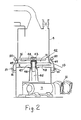
- a rotating impeller 42 (Figure 2), is mounted on a vertical shaft 45 driven at its bottom end by an electric motor 31 and gearbox 7.
- a foraminous partition 8 divides the interior of the grinding vessel into a lower plenum chamber 9 and an upper chamber 10 which contains a mixture of the material to be ground and a particulate grinding material, in the form of a bed supported on the partition 8.
- Particulate grinding medium is added, when required, through a hopper 11 mounted on the top of the grinding vessel, the bottom of the hopper being closed by a sliding gate.
- Air at a gauge pressure of up to 35 KPa is supplied to the plenum chamber through a conduit 13 from a compressor 12.
- a damper 14 is provided in the conduit to control the flow of air.
- Around the wall of the grinding vessel just above the foraminous partition is mounted a plurality of inlets 15 (there are eight in the embodiment of Figure 1, of which only five are visible) for the injection of air at a pressure in the range from 14 KPa to 140KPa into the bed of material.
- the inlets 15 are supplied by a common manifold 16 from a compressed air receiver 19, which is connected by a conduit 20 to a source of compressed air at an appropriate pressure.
- a control device 17 controls the duration and frequency of pulses of the high pressure air, and there is also an on/off valve 18.
- Additional surface active agent may be supplied through a conduit 22 and an inlet 21 at the top of the grinding chamber by means of a dosing pump 23.
- a mixture of air and finely ground particles is discharged from the grinding chamber through an outlet 24 and a conduit 25 to a bag filter assembly 26 where the finely ground material is separated from the air.
- Pulses of high pressure air are supplied from the receiver 19 through a control device 27, which controls the duration and frequency of the pulses, and a conduit 28, to a plurality of inlets 29 communicating with the interior of filter stockings (not shown) in the bag filter in order to blow accumulated solid material off the outer surface of the filter stockings. The solid material falls to the base of the bag filter assembly whence it is discharged to a bag filling assembly 30.
- the current drawn by the electric motor 31 is monitored by means of a current transformer 32 which produces an alternating current in the range 0 -5A which is proportional to the motor current.
- This alternating current is applied to a two-step controller 33 in which the alternating current is rectified and the resultant direct current passed through a network of resistors.
- a relay coil is energised or de-energised to open or close a circuit which supplies electric power to the motor 35 which drives the screw conveyor 2.
- the controller 33 and the motor 31 are connected to a main electrical switchboard by means of suitable conductors 34.
- a temperature measuring device 36 senses the temperature of the fine particle laden gas in the conduit 25.
- a relay coil is energised or de-energised to open a solenoid actuated valve 38 when the temperature in the conduit 25 rises above a given upper value and to close the valve 38 when the measured temperature falls below a given lower value.
- the solenoid valve 38 is connected on one side to a water supply 40 by means of a suitable conduit 41 and on the other side to a T piece provided in the conduit 22 for supplying surface active agent to the grinding vessel. The cooling water and the additional surface agent therefore both enter the grinding vessel through the same inlet 21.
- the rotor 42 comprises a boss 43 and four circular section bars 44 which are screwed into the boss 43 and extend radially outwardly in the form of a cross.
- the rotor 42 is driven by the shaft 45 to which power is transmitted from the electric motor 31 through the gearbox 7.
- the shaft 45 is supported in a bearing 46 and rotates with some clearance within a sleeve 47, to which clearance gas under pressure is admitted, through a conduit 48, from the stream of gas entering the plenum chamber 9 through the conduit 13.
- the inlets 15 for the injection of air at a pressure in the range from 14 K Pa to 140 K Pa into the grinding vessel are connected to the manifold 16 by eight flexible conduits 49 (only two shown), each flexible conduit having an upwardly extending loop 50. These loops inhibit the passage of solid particles along the flexible conduits and, in any case, any solid particles which enter the inlets 15 are removed by the next pulse of air. Solenoid actuated valves 51 are provided in the conduits 49 to control the timing and duration of the pulses.
- Talc having a particle size distribution such that 1% by weight consisted of particles having a diameter greater than 53 microns, 57% by weight consisted of particles having an equivalent spherical diameter larger than 10 microns and 12% by weight consisted of particles having an equivalent spherical diameter smaller than 2 microns was comminuted in a dry grinding mill similar to that shown in the Figure, but with the rotor or impeller mounted on a rotating shaft which is driven from its upper end and which is supported in bearings provided at the top of the grinding vessel. Three samples of talc were comminuted, and in each case the grinding vessel was charged with 5kg of silica sand, as grinding medium, consisting of par- tides of sizes between 0.5 mm and 1.0 mm.
- a total of 600 g of the talc was added in small discrete amounts throughout the duration of each grinding run.
- Air was supplied to the plenum chamber 9 at a pressure of 0.9 psi (6.0 KPa) but at a different volumetric flow rate for each sample of talc.
- pulses of air at a pressure of 5 psi (34.5 KPa) and a duration of 1 second were injected into the bed of sand and talc particles at a frequency of one every 20 seconds through the inlets 15.
- the finely ground talc was separated in a bag filter from the mixture of air and fine talc discharged from the outlet 24 and was tested for reflectance to light of wavelengths 457 nm and 570 nm and for specific surfaace area by the B.E.T. nitrogen adsorption method.
- talc samples were ground by a conventional wet sand grinding method using the same sand in the same size fraction as the grinding medium.
- the duration of the grinding operation was different for each of the three samples, so that a different quantity of energy was dissipated in the mixture in the grinding vessel in each case.
- a suspension of the fine talc was separated from the sand by sieving and the talc was separated by filtration and dried in an oven at 80 ° C.
- the dry talc was tested for reflectance to light of wavelengths 457 nm and 570 nm and for specific surface area by the B.E.T. method.
- Chalk having a particle size distribution such that 21% by weight consisted of particles having an equivalent spherical diameter larger than 10 microns and 38% by weight consisted of particles having an equivalent spherical diameter smaller than 2 microns was ground in the same dry grinding mill as was used in Example 1 under the same conditions as were described in Example 1 except that the pressure of the air injected in pulses through the inlets 15 was varied for different samples of the chalk.
- the product was found to have: a reflectance to light of wavelength 457 nm of 93.6 and to light of wavaelength 570 nm of 95.1; a specific surface area of 2.0 m 2 g- 1 and a particle size distribution such that 19% by weight consisted of particles having an equivalent spherical diameter larger than 20 microns, 44% by weight consisted of particles having an equivalent spherical diameter larger than 10 microns and 19% by weight consisted of particles hyaving an equivalent spherical diameter smaller than 2 microns.
- Chalk having a particle size distribution such that 10% by weight consisted of particles having an equivalent spherical diameter larger than 10 microns and 45% by weight consisted of particles having an equivalent spherical diameter smaller than 2 microns was fed at the rate of 100 grams per hour to the same dry grinding mill as was used in Example 1, the grinding vessel being charged with 5Kg of silica sand consisting of particles of sizes between 0.5mm and 1.0mm. Air was supplied to the plenum chamber 9 at a volumetric flow rate of 42 litres per minute but no additional pulses of air were used.
- a sample of mica was ground in the same dry grinding mill as was used in Example 1, 5Kg of the same silica sand being used as the grinding medium.
- the mica was fed into the mill at a rate of 605 grams per hour and a product rate of 586.3 grams per hour was achieved when air was supplied to the plenum chamber at a volumetric flow rate of 300 litres per minute. Additional pulses of air at a pressure of 5 psi (34.5 KPa) and a duration of 1 second were injected into the bed of sand and mica particles every 20 seconds through the inlets 15.
- the reflectance to light of wavelength 457nm and 570 nm, the specific surface area, and the percentage by weight of particles smaller than 10um, 2um, and 1 um, respectively, were measured for the feed and product and the results are set forth in Table IV below:
- Samples of marble chippings similar to those used in Example 3 were charged to a commercial-scale dry grinder and ground autogenously, air being supplied to the plenum chamber 9 at a flow rate of 7500 litres per minute.
- the ground marble was separated in a bag filter from the mixture of air and ground marble discharged through the outlet 24.
- Thermostats were provided in the bag filter to give a first signal when the temperature rose above an upper predetermined level and a second signal when the temperature fell below a lower predetermined level. These signals were used to open and close a solenoid operated valve which admitted water to a manifold arrangement provided with a plurality of small apertures mounted high up in the grinding vessel to supply cooling water to the mixture of air and marble chippings in the grinding vessel.
- the controls system could operate in either one of the following two modes:
Landscapes
- Engineering & Computer Science (AREA)
- Food Science & Technology (AREA)
- Crushing And Pulverization Processes (AREA)
- Disintegrating Or Milling (AREA)
- Crushing And Grinding (AREA)
- Saccharide Compounds (AREA)
- Detergent Compositions (AREA)
- Pigments, Carbon Blacks, Or Wood Stains (AREA)
- Acyclic And Carbocyclic Compounds In Medicinal Compositions (AREA)
- Processing Of Solid Wastes (AREA)
Claims (30)

Priority Applications (1)
| Application Number | Priority Date | Filing Date | Title |
|---|---|---|---|
| AT86305507T ATE51770T1 (de) | 1985-08-01 | 1986-07-17 | Zerkleinerung von material. |
Applications Claiming Priority (2)
| Application Number | Priority Date | Filing Date | Title |
|---|---|---|---|
| GB8519408A GB2190016B (en) | 1985-08-01 | 1985-08-01 | Communition of material |
| GB8519408 | 1985-08-01 |
Related Child Applications (1)
| Application Number | Title | Priority Date | Filing Date |
|---|---|---|---|
| EP89108225.7 Division-Into | 1989-05-08 |
Publications (3)
| Publication Number | Publication Date |
|---|---|
| EP0211547A2 EP0211547A2 (fr) | 1987-02-25 |
| EP0211547A3 EP0211547A3 (en) | 1988-07-13 |
| EP0211547B1 true EP0211547B1 (fr) | 1990-04-11 |
Family
ID=10583193
Family Applications (1)
| Application Number | Title | Priority Date | Filing Date |
|---|---|---|---|
| EP86305507A Expired - Lifetime EP0211547B1 (fr) | 1985-08-01 | 1986-07-17 | Broyage de matériau |
Country Status (11)
| Country | Link |
|---|---|
| US (1) | US4852811A (fr) |
| EP (1) | EP0211547B1 (fr) |
| JP (2) | JPS6291252A (fr) |
| AT (1) | ATE51770T1 (fr) |
| AU (1) | AU612860B2 (fr) |
| BR (1) | BR8603638A (fr) |
| CA (2) | CA1309997C (fr) |
| DE (2) | DE3670219D1 (fr) |
| ES (1) | ES2001171A6 (fr) |
| GB (1) | GB2190016B (fr) |
| MX (1) | MX172288B (fr) |
Families Citing this family (22)
| Publication number | Priority date | Publication date | Assignee | Title |
|---|---|---|---|---|
| DE3905806A1 (de) * | 1989-01-30 | 1990-09-06 | Lentia Gmbh | Verfahren zur kontinuierlichen trocknung von hydrophilen polymergelen |
| DE69203643T2 (de) * | 1991-04-23 | 1995-12-21 | Ecc Int Ltd | Trockenzermahlung. |
| GB9317849D0 (en) * | 1993-08-27 | 1993-10-13 | Bpb Industries Plc | Improvements in calcination |
| DE69429766D1 (de) | 1994-05-06 | 2002-03-14 | Ecc Internat Ltd | Trocknung von Suspensionen von Materialien |
| DE19611112C2 (de) * | 1996-03-21 | 2002-04-18 | Jackering Altenburger Masch | Verfahren und Vorrichtung zur Herstellung von extrem feinen Pulvern |
| DE59811597D1 (de) * | 1998-07-15 | 2004-07-29 | Hewlett Packard Co | Verfahren und Vorrichtung zur Abtrennung von Wertstoffen aus Stoffgemischen, welche schwimm-und saugfähiges Material und Metalle mit ferromagnetischem Anteil enthalten |
| US7152823B2 (en) * | 2003-02-07 | 2006-12-26 | King Machine And Tool Co. | Disc mill assembly for pulverizing system |
| US7159807B2 (en) * | 2004-09-29 | 2007-01-09 | Montag Roger A | Granular material grinder and method of use |
| US7410743B2 (en) * | 2005-05-27 | 2008-08-12 | Xerox Corporation | Imaging systems and method that form a layer on an imaging member |
| EP1992393A1 (fr) * | 2007-05-15 | 2008-11-19 | Mondo Minerals B.V. | Procédé de contrôle de la forme de particules de talc |
| EP2000213B1 (fr) * | 2007-06-08 | 2018-01-24 | Mondo Minerals B.V. | Traitement de talc dans un solvant |
| CA2743833C (fr) * | 2011-04-15 | 2017-11-21 | 2245396 Ontario Inc. | Systeme de gestion de dechets alimentaires |
| DE102011102614A1 (de) * | 2011-05-27 | 2012-11-29 | Roland Nied | Verfahren zum Betrieb einer Strahlmühle sowie Strahlmühle |
| JP2014100674A (ja) * | 2012-11-21 | 2014-06-05 | Ashizawa Finetech Ltd | メディア撹拌式分級機内蔵型粉砕機 |
| JP6168404B2 (ja) * | 2013-08-28 | 2017-07-26 | 宇部興産機械株式会社 | 粉砕システム |
| WO2015165506A1 (fr) | 2014-04-29 | 2015-11-05 | Husqvarna Ab | Outil de travail robotique amélioré |
| US20190202712A1 (en) * | 2018-01-04 | 2019-07-04 | EnviroPure Systems, Inc | Biological waste management systems |
| US20190202752A1 (en) * | 2018-01-04 | 2019-07-04 | EnviroPure Systems, Inc | Biological waste management systems |
| CN110302865B (zh) * | 2019-05-23 | 2020-11-24 | 张凤 | 一种中药超微粉末的多级粉碎装置 |
| CN110548586A (zh) * | 2019-08-01 | 2019-12-10 | 张亭亭 | 用于饮片加工的中药材破壁粉碎装置 |
| WO2021071652A1 (fr) | 2019-10-11 | 2021-04-15 | Ariens Company | Moteur électrique et ensemble lame pour une tondeuse à gazon |
| CN111468248B (zh) * | 2020-04-10 | 2021-07-23 | 吴冬波 | 一种具有安全组件的内分泌科用药物研磨装置 |
Family Cites Families (22)
| Publication number | Priority date | Publication date | Assignee | Title |
|---|---|---|---|---|
| GB956515A (en) * | 1962-03-19 | 1964-04-29 | Ici Ltd | Process for reducing particle size |
| US3202365A (en) * | 1962-04-09 | 1965-08-24 | Chemical Cleaning Inc | Phosphate recovery apparatus |
| US3168989A (en) * | 1962-05-02 | 1965-02-09 | Allis Chalmers Mfg Co | Process and equipment for the production of granulated material |
| DE1482397A1 (de) * | 1963-11-22 | 1970-03-12 | Eichborn Dipl Ing Joh Ludw V | Anwendung adsorptiver Hilfsmittel fuer Trockenmahlung |
| GB1044392A (en) * | 1964-01-10 | 1966-09-28 | Marchon Products Ltd | Improvements in fluidised beds |
| US3325105A (en) * | 1964-07-17 | 1967-06-13 | Grace W R & Co | Mineral grinding aids and process of grinding |
| GB1200551A (en) * | 1967-02-14 | 1970-07-29 | Sterling Drug Inc | Finely divided cyanuric chloride |
| FR1583182A (fr) * | 1967-11-30 | 1969-10-24 | ||
| US3565348A (en) * | 1967-12-29 | 1971-02-23 | Cities Service Co | Fluid-energy mill and process |
| US3549091A (en) * | 1968-03-14 | 1970-12-22 | Nat Lead Co | Fluid energy milling tio2 pigment |
| GB1310222A (en) * | 1969-05-15 | 1973-03-14 | English Clays Lovering Pochin | Treatment of minerals |
| US3604634A (en) * | 1969-10-28 | 1971-09-14 | English Clays Lovering Pochin | Comminution of solid materials |
| GB1319258A (en) * | 1969-11-04 | 1973-06-06 | Gen Motors Corp | Dry grinding of ceramics |
| JPS5550805Y2 (fr) * | 1975-09-09 | 1980-11-27 | ||
| GB2028785B (en) * | 1978-05-30 | 1982-09-22 | Ici Ltd | Comminution process |
| AU4263378A (en) * | 1978-12-18 | 1980-06-26 | Kintyre Ets | Disintegrating solid particles carried in a gas stream by a shock treatment |
| ZA817153B (en) * | 1980-12-19 | 1982-09-29 | Grace W R & Co | Grinding aid for granular blast furnace slag |
| GB2147296B (en) * | 1981-06-02 | 1986-05-08 | Grace W R & Co | Amine salts of aromatic carboxylic acids and grinding aids for hydraulic cement |
| US4386963A (en) * | 1981-09-21 | 1983-06-07 | W. R. Grace & Co. | Grinding aids for granular blast furnace slag |
| FR2526679B1 (fr) * | 1982-05-12 | 1988-04-08 | Poittemill Broyeurs | Perfectionnements aux broyeurs a jets |
| JPS59173144A (ja) * | 1983-03-18 | 1984-10-01 | 三菱鉱業セメント株式会社 | 塔式粉砕機 |
| HU199316B (en) * | 1983-05-24 | 1990-02-28 | Magyar Szenhidrogenipari | Method for intensifying the milling of solid inorganic matters advantageously minerals |
-
1985
- 1985-08-01 GB GB8519408A patent/GB2190016B/en not_active Expired
-
1986
- 1986-07-17 DE DE8686305507T patent/DE3670219D1/de not_active Expired - Fee Related
- 1986-07-17 EP EP86305507A patent/EP0211547B1/fr not_active Expired - Lifetime
- 1986-07-17 AT AT86305507T patent/ATE51770T1/de not_active IP Right Cessation
- 1986-07-17 DE DE3689444T patent/DE3689444T2/de not_active Expired - Fee Related
- 1986-07-31 ES ES8600758A patent/ES2001171A6/es not_active Expired
- 1986-07-31 CA CA000515036A patent/CA1309997C/fr not_active Expired - Lifetime
- 1986-07-31 BR BR8603638A patent/BR8603638A/pt not_active IP Right Cessation
- 1986-08-01 JP JP61181821A patent/JPS6291252A/ja active Granted
- 1986-08-01 MX MX003341A patent/MX172288B/es unknown
-
1988
- 1988-03-04 US US07/166,772 patent/US4852811A/en not_active Expired - Fee Related
-
1989
- 1989-06-29 AU AU37209/89A patent/AU612860B2/en not_active Expired
-
1992
- 1992-03-02 CA CA000616320A patent/CA1320705C/fr not_active Expired - Lifetime
- 1992-11-05 JP JP4296126A patent/JPH0747132B2/ja not_active Expired - Lifetime
Also Published As
| Publication number | Publication date |
|---|---|
| ES2001171A6 (es) | 1988-05-01 |
| AU6068986A (en) | 1987-02-05 |
| AU587628B2 (en) | 1989-08-24 |
| BR8603638A (pt) | 1987-03-10 |
| ATE51770T1 (de) | 1990-04-15 |
| DE3689444T2 (de) | 1994-07-07 |
| JPH05253510A (ja) | 1993-10-05 |
| GB2190016A (en) | 1987-11-11 |
| JPH0747132B2 (ja) | 1995-05-24 |
| CA1309997C (fr) | 1992-11-10 |
| EP0211547A3 (en) | 1988-07-13 |
| GB8519408D0 (en) | 1985-09-04 |
| JPS6291252A (ja) | 1987-04-25 |
| EP0211547A2 (fr) | 1987-02-25 |
| DE3689444D1 (de) | 1994-02-03 |
| AU612860B2 (en) | 1991-07-18 |
| GB2190016B (en) | 1989-07-26 |
| JPH0527461B2 (fr) | 1993-04-21 |
| MX172288B (es) | 1993-12-13 |
| US4852811A (en) | 1989-08-01 |
| DE3670219D1 (de) | 1990-05-17 |
| CA1320705C (fr) | 1993-07-27 |
| AU3720989A (en) | 1989-11-02 |
Similar Documents
| Publication | Publication Date | Title |
|---|---|---|
| US4852811A (en) | Comminution of material | |
| AU643136B2 (en) | Dry grinding | |
| KR102617677B1 (ko) | 낮은 부피 밀도의 공급 재료로부터 초미세 입자를 생산하도록 설계된 유동층 대향 제트 밀 및 이 유동층 대향 제트 밀과 관련된 방법 | |
| US5361996A (en) | Method and arrangement for finely-grinding minerals | |
| EP2542345A1 (fr) | Système et procédé de broyage en lit comprimé dans un broyeur à corps broyants agités | |
| EP0336453B1 (fr) | Procédé pour le broyage de matériau | |
| EP0681155A1 (fr) | Séchage de matériaux en suspension | |
| GB2179268A (en) | Comminution of material | |
| CA2055124C (fr) | Appareil servant a disperser une matiere | |
| US3312403A (en) | Machine and process for reclaiming foundry sand | |
| JP2503826B2 (ja) | 気流式粉砕装置 | |
| AU584489B2 (en) | Method and apparatus for improving the grinding result of a pressure chamber grinder | |
| US2587609A (en) | Impact pulverizing apparatus having fluid jets firing toward a common point | |
| US3624796A (en) | Grinding of minerals | |
| RU2082509C1 (ru) | Термоаэроклассификатор о.л.черных | |
| RU2015731C1 (ru) | Пневматическая флотационная машина | |
| JPH01502802A (ja) | 圧力室粉砕機の粉砕効率改良のための方法と装置 | |
| SU1271564A1 (ru) | Мельница | |
| WO1998001225A1 (fr) | Procede et appareil de broyage | |
| CN115970859B (zh) | 一种给料与衬板脱除的集成装置 | |
| RU2365417C1 (ru) | Способ оттирки руд | |
| SU1292828A1 (ru) | Центробежна мельница | |
| SU1701369A1 (ru) | Установка дл тонкого измельчени материалов | |
| CN204953065U (zh) | 一种用于制备农药粉剂的气流粉碎装置 | |
| KR0167010B1 (ko) | 압축성 유체를 이용한 미분체의 분쇄 방법 및 그 장치 |
Legal Events
| Date | Code | Title | Description |
|---|---|---|---|
| PUAI | Public reference made under article 153(3) epc to a published international application that has entered the european phase |
Free format text: ORIGINAL CODE: 0009012 |
|
| 17P | Request for examination filed |
Effective date: 19860804 |
|
| AK | Designated contracting states |
Kind code of ref document: A2 Designated state(s): AT BE CH DE FR IT LI LU NL SE |
|
| PUAL | Search report despatched |
Free format text: ORIGINAL CODE: 0009013 |
|
| AK | Designated contracting states |
Kind code of ref document: A3 Designated state(s): AT BE CH DE FR IT LI LU NL SE |
|
| 17Q | First examination report despatched |
Effective date: 19881024 |
|
| GRAA | (expected) grant |
Free format text: ORIGINAL CODE: 0009210 |
|
| AK | Designated contracting states |
Kind code of ref document: B1 Designated state(s): AT BE CH DE FR IT LI LU NL SE |
|
| PG25 | Lapsed in a contracting state [announced via postgrant information from national office to epo] |
Ref country code: NL Effective date: 19900411 Ref country code: LI Effective date: 19900411 Ref country code: CH Effective date: 19900411 Ref country code: AT Effective date: 19900411 |
|
| REF | Corresponds to: |
Ref document number: 51770 Country of ref document: AT Date of ref document: 19900415 Kind code of ref document: T |
|
| XX | Miscellaneous (additional remarks) |
Free format text: TEILANMELDUNG 89108225.7 EINGEREICHT AM 17/07/86. |
|
| ITF | It: translation for a ep patent filed | ||
| REF | Corresponds to: |
Ref document number: 3670219 Country of ref document: DE Date of ref document: 19900517 |
|
| ET | Fr: translation filed | ||
| PG25 | Lapsed in a contracting state [announced via postgrant information from national office to epo] |
Ref country code: LU Free format text: LAPSE BECAUSE OF NON-PAYMENT OF DUE FEES Effective date: 19900731 |
|
| REG | Reference to a national code |
Ref country code: CH Ref legal event code: PL |
|
| NLV1 | Nl: lapsed or annulled due to failure to fulfill the requirements of art. 29p and 29m of the patents act | ||
| PLBE | No opposition filed within time limit |
Free format text: ORIGINAL CODE: 0009261 |
|
| STAA | Information on the status of an ep patent application or granted ep patent |
Free format text: STATUS: NO OPPOSITION FILED WITHIN TIME LIMIT |
|
| 26N | No opposition filed | ||
| ITTA | It: last paid annual fee | ||
| EAL | Se: european patent in force in sweden |
Ref document number: 86305507.5 |
|
| PGFP | Annual fee paid to national office [announced via postgrant information from national office to epo] |
Ref country code: FR Payment date: 19960610 Year of fee payment: 11 |
|
| PGFP | Annual fee paid to national office [announced via postgrant information from national office to epo] |
Ref country code: SE Payment date: 19960614 Year of fee payment: 11 |
|
| PGFP | Annual fee paid to national office [announced via postgrant information from national office to epo] |
Ref country code: BE Payment date: 19960624 Year of fee payment: 11 |
|
| PGFP | Annual fee paid to national office [announced via postgrant information from national office to epo] |
Ref country code: DE Payment date: 19960626 Year of fee payment: 11 |
|
| PG25 | Lapsed in a contracting state [announced via postgrant information from national office to epo] |
Ref country code: SE Effective date: 19970718 |
|
| PG25 | Lapsed in a contracting state [announced via postgrant information from national office to epo] |
Ref country code: BE Free format text: LAPSE BECAUSE OF NON-PAYMENT OF DUE FEES Effective date: 19970731 |
|
| BERE | Be: lapsed |
Owner name: ECC INTERNATIONAL LTD Effective date: 19970731 |
|
| PG25 | Lapsed in a contracting state [announced via postgrant information from national office to epo] |
Ref country code: FR Free format text: LAPSE BECAUSE OF NON-PAYMENT OF DUE FEES Effective date: 19980331 |
|
| PG25 | Lapsed in a contracting state [announced via postgrant information from national office to epo] |
Ref country code: DE Free format text: LAPSE BECAUSE OF NON-PAYMENT OF DUE FEES Effective date: 19980401 |
|
| EUG | Se: european patent has lapsed |
Ref document number: 86305507.5 |
|
| REG | Reference to a national code |
Ref country code: FR Ref legal event code: ST |
|
| PG25 | Lapsed in a contracting state [announced via postgrant information from national office to epo] |
Ref country code: IT Free format text: LAPSE BECAUSE OF NON-PAYMENT OF DUE FEES;WARNING: LAPSES OF ITALIAN PATENTS WITH EFFECTIVE DATE BEFORE 2007 MAY HAVE OCCURRED AT ANY TIME BEFORE 2007. THE CORRECT EFFECTIVE DATE MAY BE DIFFERENT FROM THE ONE RECORDED. Effective date: 20050717 |