EP0211679A1 - Maschine zum Ausbreiten von gerollten Stoffbahnen - Google Patents
Maschine zum Ausbreiten von gerollten Stoffbahnen Download PDFInfo
- Publication number
- EP0211679A1 EP0211679A1 EP86306207A EP86306207A EP0211679A1 EP 0211679 A1 EP0211679 A1 EP 0211679A1 EP 86306207 A EP86306207 A EP 86306207A EP 86306207 A EP86306207 A EP 86306207A EP 0211679 A1 EP0211679 A1 EP 0211679A1
- Authority
- EP
- European Patent Office
- Prior art keywords
- cloth
- extending
- machine according
- rolled
- carriage
- Prior art date
- Legal status (The legal status is an assumption and is not a legal conclusion. Google has not performed a legal analysis and makes no representation as to the accuracy of the status listed.)
- Granted
Links
- 239000004744 fabric Substances 0.000 title claims abstract description 64
- 230000001174 ascending effect Effects 0.000 claims abstract description 8
- 230000005540 biological transmission Effects 0.000 claims 1
- 230000001360 synchronised effect Effects 0.000 description 3
- 238000000034 method Methods 0.000 description 2
- 230000015556 catabolic process Effects 0.000 description 1
- 238000010276 construction Methods 0.000 description 1
- 230000001105 regulatory effect Effects 0.000 description 1
Images

Classifications
-
- B—PERFORMING OPERATIONS; TRANSPORTING
- B65—CONVEYING; PACKING; STORING; HANDLING THIN OR FILAMENTARY MATERIAL
- B65H—HANDLING THIN OR FILAMENTARY MATERIAL, e.g. SHEETS, WEBS, CABLES
- B65H45/00—Folding thin material
- B65H45/02—Folding limp material without application of pressure to define or form crease lines
- B65H45/06—Folding webs
- B65H45/10—Folding webs transversely
- B65H45/101—Folding webs transversely in combination with laying, i.e. forming a zig-zag pile
- B65H45/103—Folding webs transversely in combination with laying, i.e. forming a zig-zag pile by a carriage which reciprocates above the laying station
-
- B—PERFORMING OPERATIONS; TRANSPORTING
- B65—CONVEYING; PACKING; STORING; HANDLING THIN OR FILAMENTARY MATERIAL
- B65H—HANDLING THIN OR FILAMENTARY MATERIAL, e.g. SHEETS, WEBS, CABLES
- B65H23/00—Registering, tensioning, smoothing or guiding webs
- B65H23/04—Registering, tensioning, smoothing or guiding webs longitudinally
- B65H23/34—Apparatus for taking-out curl from webs
Definitions
- This invention relates to a machine for extending rolled cloth which is used or unrolling rolled cloth, cuttng unrolled cloth into a fixed length and piling the cut cloth. More particularly, it relates to a machine for extending rolled cloth which comprises a carriage with running wheels and a driving source, a rolled cloth-holding stand, a cloth-supplying means provided with a draw-out roller, a cutting device, and an ascending and descending means.
- the cloth-extending operation is effected as follows: rolled cloth supported on the rolled cloth-holding stand is untied from the beginning end, supplied from the rolled cloth-holding stand to the cloth-extending portion by a draw-out roller provided on the cloth-supplying portion, introduced to the cloth-extending portion, and cut to a fixed length by the cutting means while moving on the cloth-extending stand.
- the cloth-supplying portion and the cutting device are moved up and down against the machine body by the ascending and descending means in accordance with the height of piled cloth.
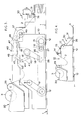
- a conventional cloth-extending machine is shown in side elevation in Fig. 4 of the accompanying drawings and has a carriage 10, wheels 12 running on a cloth-extending stand 1 and driving means such as a motor (not shown).
- a stand 20 supports a roll of cloth which is to be subjected to cloth-extending, and there is a cutting device 30 for cutting the cloth 2 into a fixed length.
- Within the carriage 10, are guide rolls 14, 15 for guiding the cloth 2 supplied from the stand 20, and also a roller 17 for feeding the cloth 2 onto the cloth-extending stand 1 by way of a slide plate 36 at the front end of the cutting device 30.
- the cutting device 30 has a blade 31 which moves in a vertical direction so as to cut the extended cloth 2 in front of the slide plate 36.
- the rolled cloth 3 is unrolled by the cloth unrolling roller 29; and guided by the guide rolls 14, 15, is drawn onto the cloth-extending stand 1 and upon the slide plate 36 of the cutting device 30 by rotation of the draw-out roller 17 which rotates at the same speed as the carriage 10.
- a carriage 10 runs a fixed distance along the cloth-extending stand 1. Then after the cloth 2 has been cut by the blade 31 of the cutting device 30 the carriage 10 returns to it's starting position. Thus, the cloth-extending operation is repeated.
- a cloth-extending machine in which the distance between the draw-out roller and the cloth-extending stand, i.e. the hanging distance, is as short as possible, so that slack parts of cloth can be eliminated.
- a cloth-extending machine according to the present invention comprises a draw-out roller, a cloth-supplying portion integrated with a cloth-holding stand, and a cutting device which can move up and down, whereby the cloth-supplying portion moves up and down in accordance with the height of piled cloth and the length of cloth hanging from the draw-out roller can be kept fixed so as to remove slack parts on the cloth.
- a particular cloth-extending machine comprises a carriage 10, a rolled cloth-holding stand 20, a cutting device 30, an ascending and descending means, which is one of the essential features of the present invention, and a cloth-supplying portion 40 integrated with the cloth-holding stand 20, the cutting device and so forth.
- a motor for driving the carriage by rotating a back wheel 12 through a sprocket 9.
- the drive to a front wheel 12 is transmitted from a sprocket 13 to a sprocket 27 of a gear box 26 through a chain 16, and then from a pulley 28 of the gear box to a draw-out roller 17 through a belt 18, a changing gear 19, a chain 41, a sprocket 42, a chain 43, a sprocket 44, a chain 45, a sprocket 46, a chain 47, a guide rod 48 and a sprocket 49, whereby the rotating force synchronized with the running of the machine carriage 10 is transmitted to the draw-out roller 17.
- the draw-out roller 17 At the front end of the cloth-supplying portion 40, is fixed the draw-out roller 17. To the back of the draw-out roller is arranged a drum 50 for guiding the cloth. On both side plates of the cloth-supplying portion there is fixed a block 7 which is mounted for guided vertical sliding movement and constitutes an ascending and descending means.
- rotation of a motor 4 for vertical driving is transmitted to a pinion 5 through a worm and wheels, engagement of the pinion 5 with a rack 6 causes the slide block 7 to slide along a rail 8 provided on the machine cariage 10, whereby the cloth-supplying portion 40 moves up and down together with the cloth-holding stand 20 and the cutting device 30.
- a motor 25 for regulating the selvage of cloth provided on the back end of the carriage, the rolled cloth-holding stand 20 is moved horizontally and in the vertical direction against the cloth-extending direction so as to regulate the selvage of cloth to be supplied.
- a cloth-unrolling roller On the rolled cloth-holding stand 20 there is installed a cloth-unrolling roller, which is rotated from a driving motor 21 through a gear 22 and a chain 23.
- Cloth 2 is supplied by rotation of the draw-out roller 17, and in accordance with the height of supplied cloth 2, as shown in Fig. 3, the rolled cloth-holding stand 20 and the cutting device 30 move upward together with the cloth-supplying portion 40 provided with the draw-out roller 17. Accordingly, the draw-out roller 17 moves upward while rotating synchronously with running of the carriage 10, during which, since each sprocket 42, 44, or 46 is connected with both cranks 51 and 52, the hanging distance of the cloth 2 between the rotating draw-out roller 17 and the cloth-slide plate 36 of the cutting device 30 and the cloth-extending portion can always be kept fixed and as short as possible.
- the length of hanging cloth from the draw-out roller to the cloth-slide plate 36 and the cloth-extending portion is very short, slackness in the cloth, influence by wind, and so forth, can be avoided, and in addition the position of the piled cloth can always be kept fixed regardless of the height of the piled cloth, whereby the cloth-extending operation can be effected stably.
- the vertical movement of the cloth-supplying portion 40 is effected by a motor 4.
- the driving means may operate by oil or air pressure.
- the draw-out roller is rotated synchronously with the running of the carriage 10 in such a manner that the rotation of the wheel 12 is transmitted through sprockets 13, 27, 42, 44, 46 and 49, gear box 26, pulley 28, belt 18, changing gear 19, and chains 16, 41, 43, 45 and 47.
- a synchronous motor may be used for driving the draw-out roller 17 at a synchronous speed as the carriage 10 moves.
- a curved cloth-slide 50 On the centre of which a timing belt (not shown) is rotated so as to remove folds in the cloth.
- a conveyer belt which can extend or shrink freely, whereby cloth is automatically passed thereon while folds in the cloth are removed.
- a guide roll can be used as conventionally.
- unrolling of cloth is effected by contacting the starting rolled cloth with the cloth-unrolling roller 29.
- unrolling of cloth may also be effected without contacting of the roIIed cloth with the cloth-unrolling roller.
- the cloth may be continuously supplied by using a bucket conveyer.
- main control circuits, base plates, and so forth are arranged in the underpart of the carriage 10, and therefore, removal or setting up of these members can easily be effected. Accordingly in case of machine breakdown, any broken members can easily be exchanged for new ones with ease.
Landscapes
- Folding Of Thin Sheet-Like Materials, Special Discharging Devices, And Others (AREA)
- Treatment Of Fiber Materials (AREA)
Priority Applications (1)
| Application Number | Priority Date | Filing Date | Title |
|---|---|---|---|
| AT86306207T ATE36301T1 (de) | 1985-08-09 | 1986-08-11 | Maschine zum ausbreiten von gerollten stoffbahnen. |
Applications Claiming Priority (2)
| Application Number | Priority Date | Filing Date | Title |
|---|---|---|---|
| JP176008/85 | 1985-08-09 | ||
| JP60176008A JPS6236275A (ja) | 1985-08-09 | 1985-08-09 | 延反機 |
Publications (2)
| Publication Number | Publication Date |
|---|---|
| EP0211679A1 true EP0211679A1 (de) | 1987-02-25 |
| EP0211679B1 EP0211679B1 (de) | 1988-08-10 |
Family
ID=16006103
Family Applications (1)
| Application Number | Title | Priority Date | Filing Date |
|---|---|---|---|
| EP86306207A Expired EP0211679B1 (de) | 1985-08-09 | 1986-08-11 | Maschine zum Ausbreiten von gerollten Stoffbahnen |
Country Status (5)
| Country | Link |
|---|---|
| US (1) | US4781366A (de) |
| EP (1) | EP0211679B1 (de) |
| JP (1) | JPS6236275A (de) |
| AT (1) | ATE36301T1 (de) |
| DE (1) | DE3660483D1 (de) |
Cited By (2)
| Publication number | Priority date | Publication date | Assignee | Title |
|---|---|---|---|---|
| EP0699607A1 (de) * | 1994-09-05 | 1996-03-06 | BULLMER SPEZIALMASCHINEN GmbH | Verfahren und Vorrichtung zum Legen von Stoff |
| CN110817562A (zh) * | 2019-11-20 | 2020-02-21 | 徐州奥拉可电子科技有限公司 | 一种机电车间用铺平机及其使用方法 |
Families Citing this family (6)
| Publication number | Priority date | Publication date | Assignee | Title |
|---|---|---|---|---|
| JPH0615926Y2 (ja) * | 1985-12-03 | 1994-04-27 | 株式会社エヌシ−エ− | 延反機 |
| DE3816882A1 (de) * | 1988-05-18 | 1989-11-30 | Krauss & Reichert Maschf | Stoffbahnlegemaschine mit stoffbahnleitflaechen |
| JPH0699076B2 (ja) * | 1990-08-10 | 1994-12-07 | 株式会社エヌシーエー | 延反機の反端払出レベル調節装置 |
| JPH0556584U (ja) * | 1991-12-27 | 1993-07-27 | 日本発条株式会社 | うず巻ばねの復元速度の調整構造 |
| US6152438A (en) * | 1997-07-23 | 2000-11-28 | Morgan; Wade | Floor supported fabric spreading machine |
| CN108557551B (zh) * | 2018-05-08 | 2023-06-20 | 苏州比阳特服装设备有限公司 | 拉布机用的下剥边装置 |
Citations (1)
| Publication number | Priority date | Publication date | Assignee | Title |
|---|---|---|---|---|
| EP0158281B1 (de) * | 1984-04-13 | 1988-07-20 | Krauss u. Reichert GmbH + Co. KG Spezialmaschinenfabrik | Stofflegemaschine |
Family Cites Families (9)
| Publication number | Priority date | Publication date | Assignee | Title |
|---|---|---|---|---|
| US3468529A (en) * | 1966-04-04 | 1969-09-23 | Cutters Machine Co Inc | Cloth laying machine having cloth roll supporting and feeding structure |
| US3503604A (en) * | 1967-07-24 | 1970-03-31 | Cutters Machine Co Inc | Cutting apparatus for cloth spreading machine |
| JPS51300B1 (de) * | 1969-01-22 | 1976-01-07 | ||
| US3811669A (en) * | 1969-09-12 | 1974-05-21 | Cutters Machine Co Inc | Electrically controlled cloth spreading machine |
| GB1357842A (en) * | 1971-04-27 | 1974-06-26 | Fonio M | Laying-up machines |
| JPS5170392A (ja) * | 1974-12-11 | 1976-06-17 | Enshu Seisaku Kk | Nunohakuchoryuyonunofurisochi |
| IT1096535B (it) * | 1978-06-09 | 1985-08-26 | Ima Spa | Apparecchiatura per la stesura di tessuti in strati sovrapposti su banchi,per industrie confezionatrici di indumenti |
| US4380330A (en) * | 1979-06-04 | 1983-04-19 | Cutters Exchange, Inc. | Catcherless cloth spreading machine |
| US4477065A (en) * | 1983-09-19 | 1984-10-16 | Cutters Exchange, Inc. | Belt feed apparatus for cloth spreading machine |
-
1985
- 1985-08-09 JP JP60176008A patent/JPS6236275A/ja active Pending
-
1986
- 1986-08-06 US US06/893,929 patent/US4781366A/en not_active Expired - Fee Related
- 1986-08-11 DE DE8686306207T patent/DE3660483D1/de not_active Expired
- 1986-08-11 EP EP86306207A patent/EP0211679B1/de not_active Expired
- 1986-08-11 AT AT86306207T patent/ATE36301T1/de not_active IP Right Cessation
Patent Citations (1)
| Publication number | Priority date | Publication date | Assignee | Title |
|---|---|---|---|---|
| EP0158281B1 (de) * | 1984-04-13 | 1988-07-20 | Krauss u. Reichert GmbH + Co. KG Spezialmaschinenfabrik | Stofflegemaschine |
Cited By (2)
| Publication number | Priority date | Publication date | Assignee | Title |
|---|---|---|---|---|
| EP0699607A1 (de) * | 1994-09-05 | 1996-03-06 | BULLMER SPEZIALMASCHINEN GmbH | Verfahren und Vorrichtung zum Legen von Stoff |
| CN110817562A (zh) * | 2019-11-20 | 2020-02-21 | 徐州奥拉可电子科技有限公司 | 一种机电车间用铺平机及其使用方法 |
Also Published As
| Publication number | Publication date |
|---|---|
| EP0211679B1 (de) | 1988-08-10 |
| DE3660483D1 (en) | 1988-09-15 |
| ATE36301T1 (de) | 1988-08-15 |
| JPS6236275A (ja) | 1987-02-17 |
| US4781366A (en) | 1988-11-01 |
Similar Documents
| Publication | Publication Date | Title |
|---|---|---|
| KR0146920B1 (ko) | 화장지등의 작은 로울의 형성을 위해 절단기와 결합된 트림제거장치 | |
| US4475729A (en) | Drive platform for fabric spreading machines | |
| US4875632A (en) | Web dividing and rewinding machine and method for removing rewind rolls therefrom | |
| FI70737B (fi) | Anordning foer infoerande av en pappersbanas oeverfoeringsremsa in i en pappersmaskins torkcylinderparti | |
| EP0211679B1 (de) | Maschine zum Ausbreiten von gerollten Stoffbahnen | |
| US4092889A (en) | Slotted worktable | |
| US4609366A (en) | Apparatus for the manufacture of plastic bags by wave-like incision to define handgrips | |
| US5282584A (en) | Belt-like material winding system | |
| JPS63180661A (ja) | 帯状材料の搬送装置 | |
| US3933068A (en) | Trim removal belt for dough cutting apparatus | |
| KR960008844B1 (ko) | 원단재단기 | |
| US3845914A (en) | Method and apparatus for cutting a web of material in a web winding machine and air lapping a cut end of the material about a winding core in the machine | |
| CN212714245U (zh) | 一种布料分切设备 | |
| US3183642A (en) | Food packaging machine | |
| US3688622A (en) | Die cutting apparatus | |
| JPH05154266A (ja) | 横方向のミシン孔線が設けられた材料のウェブからセクションを切断する装置 | |
| GB1447424A (en) | Fabric layering machines | |
| US4489872A (en) | Apparatus for producing a loop within a metal strip | |
| EP0095314B1 (de) | Federverpackungsmaschinen | |
| US3776541A (en) | Cloth folding machine | |
| US4069093A (en) | Carton sealing strip applicator | |
| CN221606160U (zh) | 一种打带缠膜一体机 | |
| EP1602581B1 (de) | Vorrichtung zum Verpacken von Gegenständen mittels Schrumpffolie | |
| US2800325A (en) | Apparatus for the assembly and finishing of sets of duplicating forms | |
| KR960037284A (ko) | 시트 요소상에 금속식 이미지를 전사하기 위한 기계내의 금속식 벨트 운반장치 및 벨트운반장치용 지지대 |
Legal Events
| Date | Code | Title | Description |
|---|---|---|---|
| PUAI | Public reference made under article 153(3) epc to a published international application that has entered the european phase |
Free format text: ORIGINAL CODE: 0009012 |
|
| AK | Designated contracting states |
Kind code of ref document: A1 Designated state(s): AT BE CH DE FR GB IT LI LU NL SE |
|
| 17P | Request for examination filed |
Effective date: 19870323 |
|
| 17Q | First examination report despatched |
Effective date: 19871105 |
|
| GRAA | (expected) grant |
Free format text: ORIGINAL CODE: 0009210 |
|
| ITF | It: translation for a ep patent filed | ||
| AK | Designated contracting states |
Kind code of ref document: B1 Designated state(s): AT BE CH DE FR GB IT LI LU NL SE |
|
| PG25 | Lapsed in a contracting state [announced via postgrant information from national office to epo] |
Ref country code: SE Effective date: 19880810 Ref country code: NL Effective date: 19880810 Ref country code: BE Effective date: 19880810 Ref country code: AT Effective date: 19880810 |
|
| REF | Corresponds to: |
Ref document number: 36301 Country of ref document: AT Date of ref document: 19880815 Kind code of ref document: T |
|
| PG25 | Lapsed in a contracting state [announced via postgrant information from national office to epo] |
Ref country code: LU Free format text: LAPSE BECAUSE OF NON-PAYMENT OF DUE FEES Effective date: 19880831 |
|
| REF | Corresponds to: |
Ref document number: 3660483 Country of ref document: DE Date of ref document: 19880915 |
|
| ET | Fr: translation filed | ||
| NLV1 | Nl: lapsed or annulled due to failure to fulfill the requirements of art. 29p and 29m of the patents act | ||
| PLBE | No opposition filed within time limit |
Free format text: ORIGINAL CODE: 0009261 |
|
| STAA | Information on the status of an ep patent application or granted ep patent |
Free format text: STATUS: NO OPPOSITION FILED WITHIN TIME LIMIT |
|
| 26N | No opposition filed | ||
| ITTA | It: last paid annual fee | ||
| PGFP | Annual fee paid to national office [announced via postgrant information from national office to epo] |
Ref country code: GB Payment date: 19970804 Year of fee payment: 12 |
|
| PGFP | Annual fee paid to national office [announced via postgrant information from national office to epo] |
Ref country code: FR Payment date: 19970811 Year of fee payment: 12 |
|
| PGFP | Annual fee paid to national office [announced via postgrant information from national office to epo] |
Ref country code: DE Payment date: 19970818 Year of fee payment: 12 |
|
| PGFP | Annual fee paid to national office [announced via postgrant information from national office to epo] |
Ref country code: CH Payment date: 19970821 Year of fee payment: 12 |
|
| PG25 | Lapsed in a contracting state [announced via postgrant information from national office to epo] |
Ref country code: GB Free format text: LAPSE BECAUSE OF NON-PAYMENT OF DUE FEES Effective date: 19980811 |
|
| PG25 | Lapsed in a contracting state [announced via postgrant information from national office to epo] |
Ref country code: LI Free format text: LAPSE BECAUSE OF NON-PAYMENT OF DUE FEES Effective date: 19980831 Ref country code: CH Free format text: LAPSE BECAUSE OF NON-PAYMENT OF DUE FEES Effective date: 19980831 |
|
| GBPC | Gb: european patent ceased through non-payment of renewal fee |
Effective date: 19980811 |
|
| REG | Reference to a national code |
Ref country code: CH Ref legal event code: PL |
|
| PG25 | Lapsed in a contracting state [announced via postgrant information from national office to epo] |
Ref country code: FR Free format text: LAPSE BECAUSE OF NON-PAYMENT OF DUE FEES Effective date: 19990430 |
|
| PG25 | Lapsed in a contracting state [announced via postgrant information from national office to epo] |
Ref country code: DE Free format text: LAPSE BECAUSE OF NON-PAYMENT OF DUE FEES Effective date: 19990601 |
|
| REG | Reference to a national code |
Ref country code: FR Ref legal event code: ST |
|
| PG25 | Lapsed in a contracting state [announced via postgrant information from national office to epo] |
Ref country code: IT Free format text: LAPSE BECAUSE OF NON-PAYMENT OF DUE FEES;WARNING: LAPSES OF ITALIAN PATENTS WITH EFFECTIVE DATE BEFORE 2007 MAY HAVE OCCURRED AT ANY TIME BEFORE 2007. THE CORRECT EFFECTIVE DATE MAY BE DIFFERENT FROM THE ONE RECORDED. Effective date: 20050811 |