EP0211984A1 - Apparat zur Eingabe und Behandlung von Computerdaten - Google Patents
Apparat zur Eingabe und Behandlung von Computerdaten Download PDFInfo
- Publication number
- EP0211984A1 EP0211984A1 EP19850110377 EP85110377A EP0211984A1 EP 0211984 A1 EP0211984 A1 EP 0211984A1 EP 19850110377 EP19850110377 EP 19850110377 EP 85110377 A EP85110377 A EP 85110377A EP 0211984 A1 EP0211984 A1 EP 0211984A1
- Authority
- EP
- European Patent Office
- Prior art keywords
- hand
- movements
- operator
- gesture
- sensing means
- Prior art date
- Legal status (The legal status is an assumption and is not a legal conclusion. Google has not performed a legal analysis and makes no representation as to the accuracy of the status listed.)
- Granted
Links
Images


Classifications
-
- G—PHYSICS
- G06—COMPUTING OR CALCULATING; COUNTING
- G06F—ELECTRIC DIGITAL DATA PROCESSING
- G06F3/00—Input arrangements for transferring data to be processed into a form capable of being handled by the computer; Output arrangements for transferring data from processing unit to output unit, e.g. interface arrangements
- G06F3/01—Input arrangements or combined input and output arrangements for interaction between user and computer
- G06F3/011—Arrangements for interaction with the human body, e.g. for user immersion in virtual reality
- G06F3/014—Hand-worn input/output arrangements, e.g. data gloves
-
- A—HUMAN NECESSITIES
- A61—MEDICAL OR VETERINARY SCIENCE; HYGIENE
- A61B—DIAGNOSIS; SURGERY; IDENTIFICATION
- A61B5/00—Measuring for diagnostic purposes; Identification of persons
- A61B5/103—Measuring devices for testing the shape, pattern, colour, size or movement of the body or parts thereof, for diagnostic purposes
- A61B5/11—Measuring movement of the entire body or parts thereof, e.g. head or hand tremor or mobility of a limb
-
- A—HUMAN NECESSITIES
- A61—MEDICAL OR VETERINARY SCIENCE; HYGIENE
- A61B—DIAGNOSIS; SURGERY; IDENTIFICATION
- A61B5/00—Measuring for diagnostic purposes; Identification of persons
- A61B5/103—Measuring devices for testing the shape, pattern, colour, size or movement of the body or parts thereof, for diagnostic purposes
- A61B5/11—Measuring movement of the entire body or parts thereof, e.g. head or hand tremor or mobility of a limb
- A61B5/1126—Measuring movement of the entire body or parts thereof, e.g. head or hand tremor or mobility of a limb using a particular sensing technique
- A61B5/1127—Measuring movement of the entire body or parts thereof, e.g. head or hand tremor or mobility of a limb using a particular sensing technique using markers
-
- A—HUMAN NECESSITIES
- A61—MEDICAL OR VETERINARY SCIENCE; HYGIENE
- A61B—DIAGNOSIS; SURGERY; IDENTIFICATION
- A61B5/00—Measuring for diagnostic purposes; Identification of persons
- A61B5/68—Arrangements of detecting, measuring or recording means, e.g. sensors, in relation to patient
- A61B5/6801—Arrangements of detecting, measuring or recording means, e.g. sensors, in relation to patient specially adapted to be attached to or worn on the body surface
- A61B5/6802—Sensor mounted on worn items
- A61B5/6804—Garments; Clothes
- A61B5/6806—Gloves
-
- A—HUMAN NECESSITIES
- A61—MEDICAL OR VETERINARY SCIENCE; HYGIENE
- A61B—DIAGNOSIS; SURGERY; IDENTIFICATION
- A61B5/00—Measuring for diagnostic purposes; Identification of persons
- A61B5/74—Details of notification to user or communication with user or patient; User input means
- A61B5/7475—User input or interface means, e.g. keyboard, pointing device, joystick
-
- G—PHYSICS
- G01—MEASURING; TESTING
- G01D—MEASURING NOT SPECIALLY ADAPTED FOR A SPECIFIC VARIABLE; ARRANGEMENTS FOR MEASURING TWO OR MORE VARIABLES NOT COVERED IN A SINGLE OTHER SUBCLASS; TARIFF METERING APPARATUS; MEASURING OR TESTING NOT OTHERWISE PROVIDED FOR
- G01D5/00—Mechanical means for transferring the output of a sensing member; Means for converting the output of a sensing member to another variable where the form or nature of the sensing member does not constrain the means for converting; Transducers not specially adapted for a specific variable
- G01D5/26—Mechanical means for transferring the output of a sensing member; Means for converting the output of a sensing member to another variable where the form or nature of the sensing member does not constrain the means for converting; Transducers not specially adapted for a specific variable characterised by optical transfer means, i.e. using infrared, visible, or ultraviolet light
- G01D5/32—Mechanical means for transferring the output of a sensing member; Means for converting the output of a sensing member to another variable where the form or nature of the sensing member does not constrain the means for converting; Transducers not specially adapted for a specific variable characterised by optical transfer means, i.e. using infrared, visible, or ultraviolet light with attenuation or whole or partial obturation of beams of light
- G01D5/34—Mechanical means for transferring the output of a sensing member; Means for converting the output of a sensing member to another variable where the form or nature of the sensing member does not constrain the means for converting; Transducers not specially adapted for a specific variable characterised by optical transfer means, i.e. using infrared, visible, or ultraviolet light with attenuation or whole or partial obturation of beams of light the beams of light being detected by photocells
- G01D5/353—Mechanical means for transferring the output of a sensing member; Means for converting the output of a sensing member to another variable where the form or nature of the sensing member does not constrain the means for converting; Transducers not specially adapted for a specific variable characterised by optical transfer means, i.e. using infrared, visible, or ultraviolet light with attenuation or whole or partial obturation of beams of light the beams of light being detected by photocells influencing the transmission properties of an optical fibre
- G01D5/35338—Mechanical means for transferring the output of a sensing member; Means for converting the output of a sensing member to another variable where the form or nature of the sensing member does not constrain the means for converting; Transducers not specially adapted for a specific variable characterised by optical transfer means, i.e. using infrared, visible, or ultraviolet light with attenuation or whole or partial obturation of beams of light the beams of light being detected by photocells influencing the transmission properties of an optical fibre using other arrangements than interferometer arrangements
- G01D5/35341—Sensor working in transmission
- G01D5/35345—Sensor working in transmission using Amplitude variations to detect the measured quantity
-
- G—PHYSICS
- G06—COMPUTING OR CALCULATING; COUNTING
- G06F—ELECTRIC DIGITAL DATA PROCESSING
- G06F3/00—Input arrangements for transferring data to be processed into a form capable of being handled by the computer; Output arrangements for transferring data from processing unit to output unit, e.g. interface arrangements
- G06F3/01—Input arrangements or combined input and output arrangements for interaction between user and computer
- G06F3/03—Arrangements for converting the position or the displacement of a member into a coded form
- G06F3/0304—Detection arrangements using opto-electronic means
-
- G—PHYSICS
- G06—COMPUTING OR CALCULATING; COUNTING
- G06F—ELECTRIC DIGITAL DATA PROCESSING
- G06F3/00—Input arrangements for transferring data to be processed into a form capable of being handled by the computer; Output arrangements for transferring data from processing unit to output unit, e.g. interface arrangements
- G06F3/01—Input arrangements or combined input and output arrangements for interaction between user and computer
- G06F3/03—Arrangements for converting the position or the displacement of a member into a coded form
- G06F3/033—Pointing devices displaced or positioned by the user, e.g. mice, trackballs, pens or joysticks; Accessories therefor
- G06F3/0338—Pointing devices displaced or positioned by the user, e.g. mice, trackballs, pens or joysticks; Accessories therefor with detection of limited linear or angular displacement of an operating part of the device from a neutral position, e.g. isotonic or isometric joysticks
-
- G—PHYSICS
- G06—COMPUTING OR CALCULATING; COUNTING
- G06F—ELECTRIC DIGITAL DATA PROCESSING
- G06F3/00—Input arrangements for transferring data to be processed into a form capable of being handled by the computer; Output arrangements for transferring data from processing unit to output unit, e.g. interface arrangements
- G06F3/01—Input arrangements or combined input and output arrangements for interaction between user and computer
- G06F3/03—Arrangements for converting the position or the displacement of a member into a coded form
- G06F3/033—Pointing devices displaced or positioned by the user, e.g. mice, trackballs, pens or joysticks; Accessories therefor
- G06F3/0346—Pointing devices displaced or positioned by the user, e.g. mice, trackballs, pens or joysticks; Accessories therefor with detection of the device orientation or free movement in a three-dimensional [3D] space, e.g. 3D mice, 6-DOF [six degrees of freedom] pointers using gyroscopes, accelerometers or tilt-sensors
-
- G—PHYSICS
- G06—COMPUTING OR CALCULATING; COUNTING
- G06F—ELECTRIC DIGITAL DATA PROCESSING
- G06F3/00—Input arrangements for transferring data to be processed into a form capable of being handled by the computer; Output arrangements for transferring data from processing unit to output unit, e.g. interface arrangements
- G06F3/01—Input arrangements or combined input and output arrangements for interaction between user and computer
- G06F3/03—Arrangements for converting the position or the displacement of a member into a coded form
- G06F3/041—Digitisers, e.g. for touch screens or touch pads, characterised by the transducing means
- G06F3/043—Digitisers, e.g. for touch screens or touch pads, characterised by the transducing means using propagating acoustic waves
-
- A—HUMAN NECESSITIES
- A61—MEDICAL OR VETERINARY SCIENCE; HYGIENE
- A61B—DIAGNOSIS; SURGERY; IDENTIFICATION
- A61B5/00—Measuring for diagnostic purposes; Identification of persons
- A61B5/103—Measuring devices for testing the shape, pattern, colour, size or movement of the body or parts thereof, for diagnostic purposes
- A61B5/11—Measuring movement of the entire body or parts thereof, e.g. head or hand tremor or mobility of a limb
- A61B5/1113—Local tracking of patients, e.g. in a hospital or private home
- A61B5/1114—Tracking parts of the body
-
- A—HUMAN NECESSITIES
- A61—MEDICAL OR VETERINARY SCIENCE; HYGIENE
- A61B—DIAGNOSIS; SURGERY; IDENTIFICATION
- A61B5/00—Measuring for diagnostic purposes; Identification of persons
- A61B5/103—Measuring devices for testing the shape, pattern, colour, size or movement of the body or parts thereof, for diagnostic purposes
- A61B5/11—Measuring movement of the entire body or parts thereof, e.g. head or hand tremor or mobility of a limb
- A61B5/1124—Determining motor skills
- A61B5/1125—Grasping motions of hands
-
- G—PHYSICS
- G05—CONTROLLING; REGULATING
- G05B—CONTROL OR REGULATING SYSTEMS IN GENERAL; FUNCTIONAL ELEMENTS OF SUCH SYSTEMS; MONITORING OR TESTING ARRANGEMENTS FOR SUCH SYSTEMS OR ELEMENTS
- G05B2219/00—Program-control systems
- G05B2219/30—Nc systems
- G05B2219/35—Nc in input of data, input till input file format
- G05B2219/35464—Glove, movement of fingers
Definitions
- This invention relates generally to the field of devices for data entry and manipulation in computers, and relates more particularly to an apparatus and method for entering data into a computer and manipulating virtual objects defined by the computer based on the gestures and positions of the hand of an operator.
- Input devices for computers include such devices as keyboards, digitizers, joysticks, mice, trackballs, and light pens.
- One function of these input devices is to position, in two dimensions, a cursor on the display screen of a computer. Once the cursor is positioned at a desired location, the computer is instructed to perform an operation.
- the processes of cursor positioning and operation selection are discrete operations, since separate motions are required to perform each operation.
- cursor positioning is accomplished by moving the mouse along a surface, while operation selection is accomplished by pushing keys located either on the mouse or a separate keyboard.
- the mastering of the operation of such input devices is often difficult because the hand movements required to operate the devices do not correspond to the visual feedback presented by the display screen of the computer.
- Glove input devices have been used to input data to computers.
- the Grimes patent discloses a glove with sensors for detecting the flexing of finger joints, sensors for detecting contact between various portions of the hand, and sensors for detecting the orientation of the hand.
- the Grimes device is adapted for the identification of static hand positions that represent the alphanumeric characters of the manual alphabet.
- the present invention provides an apparatus and method for manipulating virtual objects defined by a computer according to the gestures and positions of the hand of an operator.
- Such manipulation includes positioning a cursor or other representation of the hand of the operator with respect to virtual objects defined by the computer according to certain position specifying movements of the operator's hand, and operating on those virtual objects according to certain gesture specifying movements of the operator's hand.
- the present invention includes gesture sensing means coupled to the hand for detecting the gesture specifying movements of the hand, hand position sensing means also coupled to the hand at least in part for detecting the position specifying movements of the hand, and signal processing means adapted to receive data from the gesture sensing means and the hand position sensing means and to instruct the computer to manipulate virtual objects according to the movements of the operator's hand.
- the gesture sensing means includes a glove assembly with attached sensors that are responsive to the degree of flex of the fingers of the operator's hand. These flex sensors are mounted on a flexible printed circuit board and are sandwiched between an inner and an outer glove. A decoding circuit for addressing the sensors is also mounted on the flexible printed circuit board, and is electrically coupled to the sensors through the flexible printed circuit board and to the computer via a detachable cable.
- the hand position sensing means includes a mobile ultrasonic transmitter affixed to the glove assembly, a stationary receiver comprising three separate spaced-apart ultrasonic receiving units, and a control circuit that measures the time delay of pulsed ultrasonic signals from the transmitter to the three receivers to indicate the spatial position of the operator's hand.
- the signal processing means is embodied in software, and includes routines for positioning a hand-shaped cursor on the display screen of the computer according to the position of the operator's hand, for responding to the output signals of the flex sensors to identify gestures of the operator's hand, and for manipulating virtual objects defined by the computer according to commands represented by the gestures and movement of the operator's hand.
- the present invention comprises a computer data entry and manipulation apparatus and method capable of determining the static and dynamic gestures of an operator's hand and the spatial position of the hand.
- the present invention is especially well adapted for use with a pictorial or symbolic programming language having a dynamic cursor which corresponds in shape to the shape of the glove and moves on the screen in response to movement of the glove in space.
- the present invention provides the basis for a symbolic programming language in which the physical gestures of the operator's hand are used to implement conceptually similar and easily recognizable functions or operations on virtual objects displayed on the display screen of the computer.
- FIGS 1 through 13 of the drawings depict various preferred embodiments of the present invention for purposes of illustration only.
- One skilled in the art will readily recognize from the following discussion that alternative embodiments of the structures and methods illustrated herein may be employed without departing from the principles of the invention described herein.
- the apparatus 10 includes a glove assembly 12 that is electrically coupled to an interface circuit 14 that is in turn electrically coupled to a computer 16, a position sensing receiver assembly 18 that is also electrically coupled to the interface circuit 14, and software that is executed by the computer 16.
- the glove assembly 12 contains sensors that detect the flexing of the fingers and other gestures of the hand of an operator, and also contains an ultrasonic transducer 17 used in detecting the spatial position of the glove assembly 12.
- the position sensing receiver assembly 18 includes an L-shaped frame 20 that preferably extends across the top and down one side of a monitor 22 of the computer 16. Three ultrasonic transducers 24 are located at the corner and ends of the frame 20 and face toward the operator.
- the glove assembly 12 is worn on the hand of an operator, and is used to position a cursor 26 or other representation of the glove assembly on the display screen 28 of the computer 16.
- the spatial position of the glove assembly 12 is determined by transmitting an ultrasonic signal through the transducer 17 in the glove assembly, receiving that signal by the transducers 24 of the position sensing receiver assembly 18, and measuring the time delay of the signal from the transmitting transducer 17 to each of the receiving transducers 24.
- the software portion of the apparatus 10 converts the time delay data into orthogonal coordinates, and directs the computer 16 to display the cursor 26 on the display screen 28 accordingly.
- movement by the glove assembly 12 in a plane parallel to that of the display screen 28 results in corresponding movement by the cursor 26. Movement by the glove assembly 12 toward and away from the display screen 28 can be represented by varying the size of the cursor 26.
- the glove assembly 12 is also used to enter commands into the computer 16. As described in detail below, the glove assembly 12 contains several sensors that respond to the gestures of the operator's hand. The software portion of the apparatus 10 receives and interprets gesture indicating data from the sensors of the glove assembly 12 and enters commands into the computer 16 according to the gestures recognized. These commands relate to the manipulation of virtual objects created by the computer 16 and displayed on the display screen 28.
- FIGs 2, 3, 4, 5, and 6 the preferred embodiment of the glove assembly 12 is illustrated.
- An outer glove 30, shown in Figure 5, which protects the circuitry attached to the inner glove is not shown in Figures 2, 3, 4, and 6 to allow the apparatus to be more clearly depicted.
- the component parts of the glove assembly 12 are bonded or otherwise secured to an inner glove 32, which is worn on the hand of the operator during operation.
- the sensors and electrical components of the glove assembly are soldered to and electrically interconnected by a flexible printed circuit board 34, which is itself bonded or otherwise secured to the inner glove 22.
- the flexible printed circuit board 34 includes five elongated portions 36 positioned along the back side of the fingers and thumb and extending from a central portion 38 positioned along the back of the hand.
- the inner glove 32 is composed of a material such as stretch knitted nylon which accommodates various sizes of hands and maintains a good fit during use.
- the outer glove 30 covers and protects the components of the glove assembly 12, and improves the aesthetics of the glove assembly.
- the outer glove 30 is composed of a light weight and durable material such as cotton.
- the glove assembly 12 includes five flex sensors 40, each positioned on the back side of the inner glove 32 opposite a middle knuckle of one finger or thumb.
- the flex sensors 40 are preferably of the type that will provide a signal that is an analog representation of the degree of bend of each of the fingers and thumb.
- the flex sensor 40 comprises a flexible tube 42 having interior reflective walls with a light source 44 at one end and a photosensitive detector 46 at the other end.
- the light source 44 is preferably an infrared light emitting diode, and the photosensitive detector 46 is preferably a phototransistor.
- the flexible tube 42 is bonded or otherwise secured to the flexible printed circuit board 34, with the electrical leads of the light source 44 and the photosensitive detector 46 soldered to appropriate conductive traces of the flexible printed circuit board.
- the amount of light that impinges on the photosensitive detector 46, and the corresponding amount of current flowing through the photosensitive detector, is dependent upon the amount of bend of the flexible tube 42.
- the flexible tube 42 When the finger is extended, as shown in Figure 5, the flexible tube 42 is generally straight and a maximum amount of light from the light source 44 impinges on the photosensitive detector 46.
- the center of the flexible tube 42 is almost pinched off, which restricts the amount of light transmitted to the photosensitive detector 46.
- the flex sensors 40 provide an analog signal that indicates the flexing of the operator's fingers and thumb.
- the glove assembly 12 is electrically connected to the interface circuit 14 via a cable 52, which is preferably a flat ribbon cable that is releasably attached to the flexible printed circuit board 34 by a connector 54.
- the cable 52 also supplies power and ground signals to the components of the glove assembly 12.
- the glove assembly 12 includes an ultrasonic transducer 17 that transmits ultrasonic signals for use in determining the spatial position of the glove assembly.
- the ultrasonic transducer 17 is soldered to appropriate conductive traces at the central portion area 38 of the flexible printed circuit board 34, and is electrically connected to the interface electronics 14 via the cable 52.
- components 55 including a transformer and transistor for driving the ultrasonic transducer 17 are also contained in the glove assembly 12 and mounted to the flexible printed circuit board 34.
- three flexible transmission tubes 56, 58, and 60 are utilized to conduct the ultrasonic signals to different parts of the glove assembly.
- Transmission tubes 56 and 58 extend from the ultrasonic transducer 17 toward the index finger of the glove assembly, with transmission tube 56 ending at the base of the finger and transmission tube 58 extending nearly to the tip of the finger.
- Transmission tube 60 extends from the ultrasonic transducer 17 around the side of the glove assembly, as shown in Figure 4.
- Each of the transmission tubes carries the ultrasonic signals transmitted by the ultrasonic transducer 17 and radiates those signals out an open end.
- the transmission tubes ensure that hand gestures do not block the transmission of the ultrasonic signals to the position sensing receiver assembly 18.
- the ultrasonic signals radiating from the end of the transmission tube 58 will reach the receiving transducers 24.
- the ultrasonic signals radiating from the end of the transmision tube 56 will reach the receiving transducers 24.
- the ultrasonic signals radiating from the end of the transmission tube 60 will reach the receiving transducers 24.
- a more extensively instrumented alternative glove assembly 80 provides additional data for gesture identification.
- a flexible printed circuit board and the various electronic components of the glove assembly 80 are not shown for clarity, but may, of course, be included.
- the glove assembly 80 includes two flex sensors 82 for each finger and thumb, a flex sensor 84 between the thumb and index finger, a flex sensor 86 between the index finger and the middle finger, and a flex sensor 88 across the palm, all secured to an inner glove 90.
- the flex sensors 82 are located opposite the middle knuckle and the base knuckle of each finger and thumb.
- Flex sensor 84 is responsive to lateral movement of the thumb relative to the index finger, while flex sensor 86 is responsive to lateral movement of the index finger relative to the middle finger.
- the flex sensor 88 located across the palm is useful in detecting gestures such as touching the thumb to the little finger.
- the glove assembly 80 may also include a hand orientation sensor 92 which provides data indicative of the orientation of the glove assembly relative to the three rotational axis of roll, pitch, and yaw.
- the orientation sensor 92 can be implemented in various ways, such as a three-axis accelerometer, an array of mercury potentiometers, or a bubble gauge.
- wrist motions may be used.
- the forward and back flexing of the wrist can indicate vertical positioning of the screen cursor 26
- left and right flexing of the wrist can indicate horizontal positioning of the screen cursor.
- four additional flex sensors 94 are secured to the inner glove of the glove assembly 80 at locations surrounding the wrist joint.
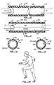
- FIG 10 illustrates in detail one implementation of the optical flex sensor employed in the glove depicted in other figures.
- the sensor 40 consists of a flexible tube 112 that has open ends 114 and 116, a reflective interior wall 118 within the flexible tube 112, and a light source 44 placed at end 114.
- a photosensitive detector 46, or light transmitting device such as an optical fiber, is placed at end 116 of tube 112 so that the intensity of a combination of direct light rays and reflected rays may be detected when the flexible tube 112 is bent.
- the flexible tube 40 may be fabricated from rubber, plastic, woven material, or other suitable flexible material, while the interior wall 118 may be coated with aluminum paint or other suitable reflective material, or in some instances left untreated.
- the tube 112 In its unflexed position, the tube 112 is generally straight. In this position the light emitted from light source 44 strikes the photosensitive detector 46. As tube 112 is bent, the light received is a combination of direct light rays and reflected rays. The amount of light reaching the photosensitive detector 46 will decrease until a position is reached in which all of the light is blocked off or reflected, depending upon the resiliency of tube 112.
- photosensitive detector 46 changes its resistance with light intensity.
- the combined effect of the bent tube 112 on the light path and the photosensitivity of the detector 46 results in a device which changes its electrical resistance (or other property) when flexed.
- Detector 46 may be a phototransistor, photosilicon-controlled rectifier, a photo cell, or an optical fiber which carries the signal to another location.
- detector 46 may be any component which has an output parameter which changes in response to light intensity.
- Figure 11 illustrates another embodiment of an optical flex sensor 124.
- Sensor 124 consists of a flexible tube 126 which has two ends 128 and 130, and a reflective interior wall 132. Interior wall 132 is constructed from two different longitudinal color areas--red 134 and green 136.
- a light source 138 for example, light-emitting diodes or infrared emitters, is positioned at one end of the tube and a photosensitive detector 140, for example, a phototransistor, is positioned at the other end 130.
- Figure 12 is a cross-sectional view of the tube shown longitudinally in Figure 11.
- optical flex sensor 142 is depicted in Figure 13.
- the sensor shown has within flexible tube 144 a reflective interior wall 146 made from three different longitudinal color areas--red 148, green 150, and yellow 152.
- the two different color areas in the sensor of Figure 12 and the three different color areas in the sensor of Figure 13 cause the intensity of the light which reaches the photosensitive detector at the opposite end of the tube to be modified according to whether a light source of similar color or different color is reflected from the surface.
- the light source may consist of the same multiple number of similar colored sources as there are colored wall areas on the wall of the tube. These multiple sources may be pulsed on and off at various time intervals, and the output parameter of the detector at the opposing end of the tube sampled during corresponding time intervals. In this manner the information present allows determination not only of the degree that the device is bent, but also the direction of bending. The accuracy obtainable with respect to the direction of bending of the device will generally increase with the larger number of multiple colored light sources and correspondingly colored walls. Although only the specific case of one, two and three colors are illustrated, any desired number may be chosen.
- Figure 14 illustrates another application for the flex sensors in which they are attached to a body suit worn by an individual.
- information may be obtained to electrically measure the position of joints and limbs, or obtain information about their velocity, acceleration or other parameters.
- Signals from the sensors may be processed for application in physical therapy, computer animation, remote control, or man/machine interface.
- the optical flex sensors may be employed as digital or analog switches.
Landscapes
- Engineering & Computer Science (AREA)
- Health & Medical Sciences (AREA)
- Life Sciences & Earth Sciences (AREA)
- Physics & Mathematics (AREA)
- Theoretical Computer Science (AREA)
- General Engineering & Computer Science (AREA)
- General Physics & Mathematics (AREA)
- Human Computer Interaction (AREA)
- Veterinary Medicine (AREA)
- Molecular Biology (AREA)
- Surgery (AREA)
- Animal Behavior & Ethology (AREA)
- General Health & Medical Sciences (AREA)
- Public Health (AREA)
- Medical Informatics (AREA)
- Heart & Thoracic Surgery (AREA)
- Biomedical Technology (AREA)
- Pathology (AREA)
- Biophysics (AREA)
- Physiology (AREA)
- Dentistry (AREA)
- Oral & Maxillofacial Surgery (AREA)
- Acoustics & Sound (AREA)
- User Interface Of Digital Computer (AREA)
- Position Input By Displaying (AREA)
- Small-Scale Networks (AREA)
- Testing Of Coins (AREA)
- Multi-Process Working Machines And Systems (AREA)
- Lock And Its Accessories (AREA)
- Information Retrieval, Db Structures And Fs Structures Therefor (AREA)
Priority Applications (3)
| Application Number | Priority Date | Filing Date | Title |
|---|---|---|---|
| DE3586204T DE3586204T3 (de) | 1985-08-19 | 1985-08-19 | Apparat zur Eingabe und Behandlung von Computerdaten. |
| EP19850110377 EP0211984B2 (de) | 1985-08-19 | 1985-08-19 | Apparat zur Eingabe und Behandlung von Computerdaten |
| AT85110377T ATE77164T1 (de) | 1985-08-19 | 1985-08-19 | Apparat zur eingabe und behandlung von computerdaten. |
Applications Claiming Priority (1)
| Application Number | Priority Date | Filing Date | Title |
|---|---|---|---|
| EP19850110377 EP0211984B2 (de) | 1985-08-19 | 1985-08-19 | Apparat zur Eingabe und Behandlung von Computerdaten |
Publications (3)
| Publication Number | Publication Date |
|---|---|
| EP0211984A1 true EP0211984A1 (de) | 1987-03-04 |
| EP0211984B1 EP0211984B1 (de) | 1992-06-10 |
| EP0211984B2 EP0211984B2 (de) | 1996-09-11 |
Family
ID=8193690
Family Applications (1)
| Application Number | Title | Priority Date | Filing Date |
|---|---|---|---|
| EP19850110377 Expired - Lifetime EP0211984B2 (de) | 1985-08-19 | 1985-08-19 | Apparat zur Eingabe und Behandlung von Computerdaten |
Country Status (3)
| Country | Link |
|---|---|
| EP (1) | EP0211984B2 (de) |
| AT (1) | ATE77164T1 (de) |
| DE (1) | DE3586204T3 (de) |
Cited By (41)
| Publication number | Priority date | Publication date | Assignee | Title |
|---|---|---|---|---|
| DE3842513A1 (de) * | 1988-12-16 | 1990-06-21 | Id Ges Fuer Beratung Und Innov | Arbeitsverfahren zum gezielten informationsabruf aus einem computerprogramm |
| EP0432160A4 (en) * | 1988-07-20 | 1991-11-13 | Arthur D. Little, Inc. | Hand position/measurement control system |
| EP0352291A4 (en) * | 1987-03-24 | 1991-12-04 | Vpl Research, Inc. | Motion sensor |
| EP0422003A4 (en) * | 1988-02-29 | 1992-01-02 | Dimensional Data, Inc. | Computer based upper extremity evaluation system |
| DE4114926C1 (en) * | 1991-05-07 | 1992-09-17 | Michael 6500 Mainz De Flanz | Data processing installation with optical input unit - includes optical transmitter worn by user, esp. handicapped or spastic person, generating light beam |
| EP0526015A1 (de) * | 1991-07-08 | 1993-02-03 | PEGASUS TECHNOLOGIES Ltd. | Dreidimensionale Rechnermaus |
| EP0549177A1 (de) * | 1991-12-23 | 1993-06-30 | General Electric Company | Fernbedienung für einen elektronischen Gerät |
| WO1993015476A1 (en) * | 1992-01-27 | 1993-08-05 | Mie Modern Information Technology And Electronics Development, Services And Sales Co. Ltd. | Transducer arrangement for controlling machine(s) by perception of distance, especially for making choices from the computer's menu |
| EP0531644A3 (en) * | 1991-09-09 | 1993-12-15 | Psc Inc | Portable transaction terminal for optical and key entry of data without keyboards and manually actuated scanners |
| FR2697740A1 (fr) * | 1992-11-10 | 1994-05-13 | Felman Daniel | Appareil de relaxation externe du rachis. |
| EP0666544A1 (de) * | 1994-02-03 | 1995-08-09 | Canon Kabushiki Kaisha | Gesteneingabeverfahren und Gerät |
| GB2291167A (en) * | 1994-07-15 | 1996-01-17 | Virtuality | Computer input device eg for virtual reality |
| WO1996009918A1 (en) * | 1994-09-28 | 1996-04-04 | Faeger Jan G | Control equipment with a movable control member |
| WO1996020644A1 (en) * | 1995-01-04 | 1996-07-11 | University Of Alberta | Differential myometer |
| AT402119B (de) * | 1994-09-06 | 1997-02-25 | Siemens Ag Oesterreich | System zur speicherung von bilddaten |
| DE19632273A1 (de) * | 1996-08-09 | 1998-02-12 | Helge Zwosta | Körpersensorik |
| WO1998007368A1 (en) * | 1996-08-21 | 1998-02-26 | GETTLER, Ján | Data glove for sensing movements |
| EP0789320A3 (de) * | 1996-02-09 | 1998-10-21 | Pegasus Technologies Ltd. | Rechnermaus und Halter |
| DE19750441A1 (de) * | 1997-11-14 | 1999-06-10 | Markus Becker | Einrichtung zur Erfassung und Steuerung von Körperhaltungen |
| DE19830359A1 (de) * | 1998-07-07 | 2000-01-20 | Helge Zwosta | Räumliche Lage- und Bewegungsbestimmung von Körperteilen und Körpern, mittels einer Kombination von inertialen Orientierungs-Meßaufnehmern und Positionserfassungssensoriken |
| US6072466A (en) * | 1996-08-02 | 2000-06-06 | U.S. Philips Corporation | Virtual environment manipulation device modelling and control |
| FR2786899A1 (fr) * | 1998-12-03 | 2000-06-09 | Jean Bonnard | Indicateur de mouvements pour logiciels |
| US6285379B1 (en) | 1995-12-07 | 2001-09-04 | U.S. Philips Corporation | Virtual body control device |
| RU2339087C2 (ru) * | 2001-09-07 | 2008-11-20 | Хармоник Рисерч, Инк. | Улучшенное беспроводное устройство управления |
| US7702477B2 (en) | 2006-07-05 | 2010-04-20 | Aesculap Ag | Calibration method and calibration device for a surgical referencing unit |
| WO2013168056A1 (en) * | 2012-05-10 | 2013-11-14 | Koninklijke Philips N.V. | Gesture control |
| WO2016183606A1 (en) * | 2015-05-21 | 2016-11-24 | Cakmak Tuncay | Sexual interaction device and method for providing an enhanced computer mediated sexual experience to a user |
| CN107817911A (zh) * | 2017-09-13 | 2018-03-20 | 杨长明 | 一种终端控制方法及其控制设备 |
| WO2018231570A1 (en) * | 2017-06-13 | 2018-12-20 | Bebop Sensors, Inc. | Sensor system integrated with a glove |
| DE102017121991A1 (de) * | 2017-09-22 | 2019-03-28 | Deutsches Zentrum für Luft- und Raumfahrt e.V. | Sensoranordnung zum Erfassen von Daumenbewegungen sowie Eingabegerät und Verfahren zum Erfassen von Hand- und/oder Fingerbewegungen |
| US10282011B2 (en) | 2014-05-15 | 2019-05-07 | Bebop Sensors, Inc. | Flexible sensors and applications |
| US10288507B2 (en) | 2009-10-16 | 2019-05-14 | Bebop Sensors, Inc. | Piezoresistive sensors and sensor arrays |
| US10352787B2 (en) | 2015-02-27 | 2019-07-16 | Bebop Sensors, Inc. | Sensor systems integrated with footwear |
| US10362989B2 (en) | 2014-06-09 | 2019-07-30 | Bebop Sensors, Inc. | Sensor system integrated with a glove |
| CN110623673A (zh) * | 2019-09-29 | 2019-12-31 | 华东交通大学 | 一种用于驾驶员手势识别的全柔性智能腕带 |
| US10654486B2 (en) | 2015-06-25 | 2020-05-19 | Bebop Sensors, Inc. | Sensor systems integrated with steering wheels |
| US10802641B2 (en) | 2012-03-14 | 2020-10-13 | Bebop Sensors, Inc. | Piezoresistive sensors and applications |
| US10884496B2 (en) | 2018-07-05 | 2021-01-05 | Bebop Sensors, Inc. | One-size-fits-all data glove |
| CN112416130A (zh) * | 2020-11-24 | 2021-02-26 | 谢昊 | 一种智能运动检测装置及方法 |
| CN112971773A (zh) * | 2021-03-12 | 2021-06-18 | 哈尔滨工业大学 | 基于手掌弯曲信息的人手运动模式识别系统 |
| US11480481B2 (en) | 2019-03-13 | 2022-10-25 | Bebop Sensors, Inc. | Alignment mechanisms sensor systems employing piezoresistive materials |
Families Citing this family (12)
| Publication number | Priority date | Publication date | Assignee | Title |
|---|---|---|---|---|
| US8545488B2 (en) | 2004-09-17 | 2013-10-01 | The Spectranetics Corporation | Cardiovascular imaging system |
| DE102010019356B4 (de) * | 2010-05-05 | 2018-04-05 | Deutsches Zentrum für Luft- und Raumfahrt e.V. | Verfahren zum Erfassen von Bewegungen einer menschlichen Hand |
| DE102011088681A1 (de) | 2011-12-15 | 2013-06-20 | Endress + Hauser Wetzer Gmbh + Co Kg | Verfahren zur Bedienung eines Feldgerätes der Automatisierungstechnik sowie ein Feldgerät |
| US9623211B2 (en) | 2013-03-13 | 2017-04-18 | The Spectranetics Corporation | Catheter movement control |
| US9757200B2 (en) | 2013-03-14 | 2017-09-12 | The Spectranetics Corporation | Intelligent catheter |
| US11642169B2 (en) | 2013-03-14 | 2023-05-09 | The Spectranetics Corporation | Smart multiplexed medical laser system |
| US10758308B2 (en) | 2013-03-14 | 2020-09-01 | The Spectranetics Corporation | Controller to select optical channel parameters in a catheter |
| PL2916210T3 (pl) | 2014-03-05 | 2018-01-31 | Markantus Ag | Urządzenie noszone na palcu do dostarczania sygnałów wejściowych użytkownika |
| US10987168B2 (en) | 2014-05-29 | 2021-04-27 | Spectranetics Llc | System and method for coordinated laser delivery and imaging |
| US10646275B2 (en) | 2014-12-30 | 2020-05-12 | Regents Of The University Of Minnesota | Laser catheter with use of determined material type in vascular system in ablation of material |
| US10646274B2 (en) | 2014-12-30 | 2020-05-12 | Regents Of The University Of Minnesota | Laser catheter with use of reflected light and force indication to determine material type in vascular system |
| US10646118B2 (en) | 2014-12-30 | 2020-05-12 | Regents Of The University Of Minnesota | Laser catheter with use of reflected light to determine material type in vascular system |
Citations (5)
| Publication number | Priority date | Publication date | Assignee | Title |
|---|---|---|---|---|
| US4414537A (en) * | 1981-09-15 | 1983-11-08 | Bell Telephone Laboratories, Incorporated | Digital data entry glove interface device |
| EP0121387A2 (de) * | 1983-03-31 | 1984-10-10 | Interand Corporation | System zur Abtastung von Raum-Koordination |
| EP0123043A1 (de) * | 1983-04-20 | 1984-10-31 | International Business Machines Corporation | Geschwindigkeitsmessvorrichtung und Verfahren zur Cursorsteuerung |
| DE3334395A1 (de) * | 1983-09-23 | 1985-04-11 | Fraunhofer-Gesellschaft zur Förderung der angewandten Forschung e.V., 8000 München | Optische messvorrichtung fuer biegung und auslenkung |
| US4542291A (en) * | 1982-09-29 | 1985-09-17 | Vpl Research Inc. | Optical flex sensor |
-
1985
- 1985-08-19 EP EP19850110377 patent/EP0211984B2/de not_active Expired - Lifetime
- 1985-08-19 AT AT85110377T patent/ATE77164T1/de not_active IP Right Cessation
- 1985-08-19 DE DE3586204T patent/DE3586204T3/de not_active Expired - Lifetime
Patent Citations (5)
| Publication number | Priority date | Publication date | Assignee | Title |
|---|---|---|---|---|
| US4414537A (en) * | 1981-09-15 | 1983-11-08 | Bell Telephone Laboratories, Incorporated | Digital data entry glove interface device |
| US4542291A (en) * | 1982-09-29 | 1985-09-17 | Vpl Research Inc. | Optical flex sensor |
| EP0121387A2 (de) * | 1983-03-31 | 1984-10-10 | Interand Corporation | System zur Abtastung von Raum-Koordination |
| EP0123043A1 (de) * | 1983-04-20 | 1984-10-31 | International Business Machines Corporation | Geschwindigkeitsmessvorrichtung und Verfahren zur Cursorsteuerung |
| DE3334395A1 (de) * | 1983-09-23 | 1985-04-11 | Fraunhofer-Gesellschaft zur Förderung der angewandten Forschung e.V., 8000 München | Optische messvorrichtung fuer biegung und auslenkung |
Cited By (55)
| Publication number | Priority date | Publication date | Assignee | Title |
|---|---|---|---|---|
| EP0352291A4 (en) * | 1987-03-24 | 1991-12-04 | Vpl Research, Inc. | Motion sensor |
| EP0422003A4 (en) * | 1988-02-29 | 1992-01-02 | Dimensional Data, Inc. | Computer based upper extremity evaluation system |
| EP0432160A4 (en) * | 1988-07-20 | 1991-11-13 | Arthur D. Little, Inc. | Hand position/measurement control system |
| DE3842513A1 (de) * | 1988-12-16 | 1990-06-21 | Id Ges Fuer Beratung Und Innov | Arbeitsverfahren zum gezielten informationsabruf aus einem computerprogramm |
| DE4114926C1 (en) * | 1991-05-07 | 1992-09-17 | Michael 6500 Mainz De Flanz | Data processing installation with optical input unit - includes optical transmitter worn by user, esp. handicapped or spastic person, generating light beam |
| EP0526015A1 (de) * | 1991-07-08 | 1993-02-03 | PEGASUS TECHNOLOGIES Ltd. | Dreidimensionale Rechnermaus |
| EP0531644A3 (en) * | 1991-09-09 | 1993-12-15 | Psc Inc | Portable transaction terminal for optical and key entry of data without keyboards and manually actuated scanners |
| EP0549177A1 (de) * | 1991-12-23 | 1993-06-30 | General Electric Company | Fernbedienung für einen elektronischen Gerät |
| US5528264A (en) * | 1991-12-23 | 1996-06-18 | General Electric Company | Wireless remote control for electronic equipment |
| WO1993015476A1 (en) * | 1992-01-27 | 1993-08-05 | Mie Modern Information Technology And Electronics Development, Services And Sales Co. Ltd. | Transducer arrangement for controlling machine(s) by perception of distance, especially for making choices from the computer's menu |
| FR2697740A1 (fr) * | 1992-11-10 | 1994-05-13 | Felman Daniel | Appareil de relaxation externe du rachis. |
| EP0666544A1 (de) * | 1994-02-03 | 1995-08-09 | Canon Kabushiki Kaisha | Gesteneingabeverfahren und Gerät |
| US5714698A (en) * | 1994-02-03 | 1998-02-03 | Canon Kabushiki Kaisha | Gesture input method and apparatus |
| GB2291167A (en) * | 1994-07-15 | 1996-01-17 | Virtuality | Computer input device eg for virtual reality |
| AT402119B (de) * | 1994-09-06 | 1997-02-25 | Siemens Ag Oesterreich | System zur speicherung von bilddaten |
| WO1996009918A1 (en) * | 1994-09-28 | 1996-04-04 | Faeger Jan G | Control equipment with a movable control member |
| US6157368A (en) * | 1994-09-28 | 2000-12-05 | Faeger; Jan G. | Control equipment with a movable control member |
| WO1996020644A1 (en) * | 1995-01-04 | 1996-07-11 | University Of Alberta | Differential myometer |
| US5911693A (en) * | 1995-01-04 | 1999-06-15 | University Of Alberta | Differential myometer |
| US6285379B1 (en) | 1995-12-07 | 2001-09-04 | U.S. Philips Corporation | Virtual body control device |
| EP0789320A3 (de) * | 1996-02-09 | 1998-10-21 | Pegasus Technologies Ltd. | Rechnermaus und Halter |
| US6072466A (en) * | 1996-08-02 | 2000-06-06 | U.S. Philips Corporation | Virtual environment manipulation device modelling and control |
| DE19632273A1 (de) * | 1996-08-09 | 1998-02-12 | Helge Zwosta | Körpersensorik |
| WO1998007086A1 (de) * | 1996-08-09 | 1998-02-19 | Helge Zwosta | Körpersensorik |
| WO1998007368A1 (en) * | 1996-08-21 | 1998-02-26 | GETTLER, Ján | Data glove for sensing movements |
| DE19750441C2 (de) * | 1997-11-14 | 2000-01-27 | Markus Becker | Vorrichtung zur Erfassung und Steuerung von Körperhaltungen zur therapeutischen Anwendung in sitzender Haltung |
| WO1999025237A3 (de) * | 1997-11-14 | 1999-07-15 | Siemens Ag | Verfahren und vorrichtung zum training von körperteilen eines menschen |
| DE19750441A1 (de) * | 1997-11-14 | 1999-06-10 | Markus Becker | Einrichtung zur Erfassung und Steuerung von Körperhaltungen |
| US6334837B1 (en) | 1997-11-14 | 2002-01-01 | Achim Hein | Method and device for training body parts of a person |
| DE19830359A1 (de) * | 1998-07-07 | 2000-01-20 | Helge Zwosta | Räumliche Lage- und Bewegungsbestimmung von Körperteilen und Körpern, mittels einer Kombination von inertialen Orientierungs-Meßaufnehmern und Positionserfassungssensoriken |
| FR2786899A1 (fr) * | 1998-12-03 | 2000-06-09 | Jean Bonnard | Indicateur de mouvements pour logiciels |
| RU2339087C2 (ru) * | 2001-09-07 | 2008-11-20 | Хармоник Рисерч, Инк. | Улучшенное беспроводное устройство управления |
| US7702477B2 (en) | 2006-07-05 | 2010-04-20 | Aesculap Ag | Calibration method and calibration device for a surgical referencing unit |
| US10288507B2 (en) | 2009-10-16 | 2019-05-14 | Bebop Sensors, Inc. | Piezoresistive sensors and sensor arrays |
| US10753814B2 (en) | 2009-10-16 | 2020-08-25 | Bebop Sensors, Inc. | Piezoresistive sensors and sensor arrays |
| US11204664B2 (en) | 2012-03-14 | 2021-12-21 | Bebop Sensors, Inc | Piezoresistive sensors and applications |
| US10802641B2 (en) | 2012-03-14 | 2020-10-13 | Bebop Sensors, Inc. | Piezoresistive sensors and applications |
| WO2013168056A1 (en) * | 2012-05-10 | 2013-11-14 | Koninklijke Philips N.V. | Gesture control |
| US9483122B2 (en) | 2012-05-10 | 2016-11-01 | Koninklijke Philips N.V. | Optical shape sensing device and gesture control |
| US10282011B2 (en) | 2014-05-15 | 2019-05-07 | Bebop Sensors, Inc. | Flexible sensors and applications |
| US11147510B2 (en) | 2014-06-09 | 2021-10-19 | Bebop Sensors, Inc. | Flexible sensors and sensor systems |
| US10362989B2 (en) | 2014-06-09 | 2019-07-30 | Bebop Sensors, Inc. | Sensor system integrated with a glove |
| US10352787B2 (en) | 2015-02-27 | 2019-07-16 | Bebop Sensors, Inc. | Sensor systems integrated with footwear |
| WO2016183606A1 (en) * | 2015-05-21 | 2016-11-24 | Cakmak Tuncay | Sexual interaction device and method for providing an enhanced computer mediated sexual experience to a user |
| US10654486B2 (en) | 2015-06-25 | 2020-05-19 | Bebop Sensors, Inc. | Sensor systems integrated with steering wheels |
| WO2018231570A1 (en) * | 2017-06-13 | 2018-12-20 | Bebop Sensors, Inc. | Sensor system integrated with a glove |
| CN107817911B (zh) * | 2017-09-13 | 2024-01-30 | 杨长明 | 一种终端控制方法及其控制设备 |
| CN107817911A (zh) * | 2017-09-13 | 2018-03-20 | 杨长明 | 一种终端控制方法及其控制设备 |
| DE102017121991A1 (de) * | 2017-09-22 | 2019-03-28 | Deutsches Zentrum für Luft- und Raumfahrt e.V. | Sensoranordnung zum Erfassen von Daumenbewegungen sowie Eingabegerät und Verfahren zum Erfassen von Hand- und/oder Fingerbewegungen |
| US10884496B2 (en) | 2018-07-05 | 2021-01-05 | Bebop Sensors, Inc. | One-size-fits-all data glove |
| US11480481B2 (en) | 2019-03-13 | 2022-10-25 | Bebop Sensors, Inc. | Alignment mechanisms sensor systems employing piezoresistive materials |
| CN110623673A (zh) * | 2019-09-29 | 2019-12-31 | 华东交通大学 | 一种用于驾驶员手势识别的全柔性智能腕带 |
| CN112416130A (zh) * | 2020-11-24 | 2021-02-26 | 谢昊 | 一种智能运动检测装置及方法 |
| CN112416130B (zh) * | 2020-11-24 | 2023-03-21 | 谢昊 | 一种智能运动检测装置及方法 |
| CN112971773A (zh) * | 2021-03-12 | 2021-06-18 | 哈尔滨工业大学 | 基于手掌弯曲信息的人手运动模式识别系统 |
Also Published As
| Publication number | Publication date |
|---|---|
| ATE77164T1 (de) | 1992-06-15 |
| DE3586204T3 (de) | 1997-01-23 |
| EP0211984B1 (de) | 1992-06-10 |
| DE3586204T2 (de) | 1992-12-03 |
| DE3586204D1 (de) | 1992-07-16 |
| EP0211984B2 (de) | 1996-09-11 |
Similar Documents
| Publication | Publication Date | Title |
|---|---|---|
| EP0211984B1 (de) | Apparat zur Eingabe und Behandlung von Computerdaten | |
| US6424334B1 (en) | Computer data entry and manipulation apparatus and method | |
| US4954817A (en) | Finger worn graphic interface device | |
| US5095302A (en) | Three dimensional mouse via finger ring or cavity | |
| US5488362A (en) | Apparatus for controlling a video game | |
| US5341133A (en) | Keyboard having touch sensor keys for conveying information electronically | |
| JPH0363089B2 (de) | ||
| US6677927B1 (en) | X-Y navigation input device | |
| US4550250A (en) | Cordless digital graphics input device | |
| US8199114B1 (en) | Touch sensor control devices | |
| US6184863B1 (en) | Direct pointing apparatus and method therefor | |
| US4542291A (en) | Optical flex sensor | |
| US4937444A (en) | Optical flex sensor | |
| US20100103104A1 (en) | Apparatus for user interface based on wearable computing environment and method thereof | |
| GB2264016A (en) | Wireless input device for computer. | |
| US20080042993A1 (en) | Sensor pad using light pipe input devices | |
| US7768499B2 (en) | Mouth-operated computer input device and associated methods | |
| US6833825B1 (en) | Apparatus for remotely controlling a digital processing system | |
| RU179301U1 (ru) | Перчатка виртуальной реальности | |
| RU187548U1 (ru) | Перчатка виртуальной реальности | |
| RU2670649C1 (ru) | Способ изготовления перчатки виртуальной реальности (варианты) | |
| JP3126898B2 (ja) | 頭部搭載型ディスプレイ装置 | |
| EP0352291A4 (en) | Motion sensor | |
| US6707445B1 (en) | Input device | |
| JPH1131047A (ja) | 記号信号生成装置 |
Legal Events
| Date | Code | Title | Description |
|---|---|---|---|
| PUAI | Public reference made under article 153(3) epc to a published international application that has entered the european phase |
Free format text: ORIGINAL CODE: 0009012 |
|
| AK | Designated contracting states |
Kind code of ref document: A1 Designated state(s): AT BE CH DE FR GB IT LI LU NL SE |
|
| 17P | Request for examination filed |
Effective date: 19870821 |
|
| 17Q | First examination report despatched |
Effective date: 19890412 |
|
| GRAA | (expected) grant |
Free format text: ORIGINAL CODE: 0009210 |
|
| AK | Designated contracting states |
Kind code of ref document: B1 Designated state(s): AT BE CH DE FR GB IT LI LU NL SE |
|
| REF | Corresponds to: |
Ref document number: 77164 Country of ref document: AT Date of ref document: 19920615 Kind code of ref document: T |
|
| REF | Corresponds to: |
Ref document number: 3586204 Country of ref document: DE Date of ref document: 19920716 |
|
| ITF | It: translation for a ep patent filed | ||
| ET | Fr: translation filed | ||
| ITPR | It: changes in ownership of a european patent |
Owner name: C.NE EPO REG. 20;VPL RESEARCH INC. |
|
| PLBI | Opposition filed |
Free format text: ORIGINAL CODE: 0009260 |
|
| 26 | Opposition filed |
Opponent name: W INDUSTRIES LIMITED Effective date: 19930304 |
|
| RAP2 | Party data changed (patent owner data changed or rights of a patent transferred) |
Owner name: VPL RESEARCH, INC. |
|
| NLR1 | Nl: opposition has been filed with the epo |
Opponent name: W INDUSTRIES LIMITED |
|
| NLT2 | Nl: modifications (of names), taken from the european patent patent bulletin |
Owner name: VPL RESEARCH, INC. TE FOSTER CITY, CALIFORNIE, VER |
|
| EPTA | Lu: last paid annual fee | ||
| EAL | Se: european patent in force in sweden |
Ref document number: 85110377.0 |
|
| PLAB | Opposition data, opponent's data or that of the opponent's representative modified |
Free format text: ORIGINAL CODE: 0009299OPPO |
|
| R26 | Opposition filed (corrected) |
Opponent name: VIRTUALITY ENTERTAINMENT LIMITED Effective date: 19930304 |
|
| APAC | Appeal dossier modified |
Free format text: ORIGINAL CODE: EPIDOS NOAPO |
|
| NLR1 | Nl: opposition has been filed with the epo |
Opponent name: VIRTUALITY ENTERTAINMENT LIMITED |
|
| PLAW | Interlocutory decision in opposition |
Free format text: ORIGINAL CODE: EPIDOS IDOP |
|
| PLAW | Interlocutory decision in opposition |
Free format text: ORIGINAL CODE: EPIDOS IDOP |
|
| PUAH | Patent maintained in amended form |
Free format text: ORIGINAL CODE: 0009272 |
|
| STAA | Information on the status of an ep patent application or granted ep patent |
Free format text: STATUS: PATENT MAINTAINED AS AMENDED |
|
| 27A | Patent maintained in amended form |
Effective date: 19960911 |
|
| AK | Designated contracting states |
Kind code of ref document: B2 Designated state(s): AT BE CH DE FR GB IT LI LU NL SE |
|
| PG25 | Lapsed in a contracting state [announced via postgrant information from national office to epo] |
Ref country code: AT Free format text: LAPSE BECAUSE OF NON-PAYMENT OF DUE FEES Effective date: 19960911 |
|
| ET3 | Fr: translation filed ** decision concerning opposition | ||
| REG | Reference to a national code |
Ref country code: CH Ref legal event code: PUE Owner name: JARON Z. LANIER;THOMAS G. ZIMMERMANN TRANSFER- VPL Ref country code: CH Ref legal event code: NV Representative=s name: KIRKER & CIE SA Ref country code: CH Ref legal event code: AEN Free format text: MAINTIEN DU BREVET DONT L'ETENDUE A ETE MODIFIEE |
|
| ITF | It: translation for a ep patent filed | ||
| NLR2 | Nl: decision of opposition | ||
| NLR3 | Nl: receipt of modified translations in the netherlands language after an opposition procedure | ||
| NLS | Nl: assignments of ep-patents |
Owner name: VPL RESEARCH, INC. |
|
| PGFP | Annual fee paid to national office [announced via postgrant information from national office to epo] |
Ref country code: AT Payment date: 19970807 Year of fee payment: 13 |
|
| REG | Reference to a national code |
Ref country code: GB Ref legal event code: 732E |
|
| REG | Reference to a national code |
Ref country code: FR Ref legal event code: TP |
|
| REG | Reference to a national code |
Ref country code: FR Ref legal event code: TP |
|
| REG | Reference to a national code |
Ref country code: CH Ref legal event code: PUE Owner name: VPL RESEARCH, INC. TRANSFER- SUN MICROSYSTEMS, INC Ref country code: CH Ref legal event code: NV Representative=s name: MICHELI & CIE INGENIEURS-CONSEILS |
|
| REG | Reference to a national code |
Ref country code: GB Ref legal event code: 732E |
|
| REG | Reference to a national code |
Ref country code: GB Ref legal event code: IF02 |
|
| PGFP | Annual fee paid to national office [announced via postgrant information from national office to epo] |
Ref country code: BE Payment date: 20020723 Year of fee payment: 18 |
|
| PGFP | Annual fee paid to national office [announced via postgrant information from national office to epo] |
Ref country code: LU Payment date: 20020828 Year of fee payment: 18 |
|
| PGFP | Annual fee paid to national office [announced via postgrant information from national office to epo] |
Ref country code: CH Payment date: 20020916 Year of fee payment: 18 |
|
| PG25 | Lapsed in a contracting state [announced via postgrant information from national office to epo] |
Ref country code: LU Free format text: LAPSE BECAUSE OF NON-PAYMENT OF DUE FEES Effective date: 20030819 |
|
| PG25 | Lapsed in a contracting state [announced via postgrant information from national office to epo] |
Ref country code: LI Free format text: LAPSE BECAUSE OF NON-PAYMENT OF DUE FEES Effective date: 20030831 Ref country code: CH Free format text: LAPSE BECAUSE OF NON-PAYMENT OF DUE FEES Effective date: 20030831 Ref country code: BE Free format text: LAPSE BECAUSE OF NON-PAYMENT OF DUE FEES Effective date: 20030831 |
|
| BERE | Be: lapsed |
Owner name: *SUN MICROSYSTEMS INC. Effective date: 20030831 |
|
| REG | Reference to a national code |
Ref country code: CH Ref legal event code: PL |
|
| PGFP | Annual fee paid to national office [announced via postgrant information from national office to epo] |
Ref country code: NL Payment date: 20040803 Year of fee payment: 20 |
|
| PGFP | Annual fee paid to national office [announced via postgrant information from national office to epo] |
Ref country code: SE Payment date: 20040806 Year of fee payment: 20 |
|
| PGFP | Annual fee paid to national office [announced via postgrant information from national office to epo] |
Ref country code: FR Payment date: 20040810 Year of fee payment: 20 |
|
| PGFP | Annual fee paid to national office [announced via postgrant information from national office to epo] |
Ref country code: GB Payment date: 20040818 Year of fee payment: 20 |
|
| PGFP | Annual fee paid to national office [announced via postgrant information from national office to epo] |
Ref country code: DE Payment date: 20040826 Year of fee payment: 20 |
|
| PG25 | Lapsed in a contracting state [announced via postgrant information from national office to epo] |
Ref country code: GB Free format text: LAPSE BECAUSE OF EXPIRATION OF PROTECTION Effective date: 20050818 |
|
| PG25 | Lapsed in a contracting state [announced via postgrant information from national office to epo] |
Ref country code: NL Free format text: LAPSE BECAUSE OF EXPIRATION OF PROTECTION Effective date: 20050819 |
|
| REG | Reference to a national code |
Ref country code: GB Ref legal event code: PE20 |
|
| NLV7 | Nl: ceased due to reaching the maximum lifetime of a patent |
Effective date: 20050819 |
|
| EUG | Se: european patent has lapsed | ||
| APAH | Appeal reference modified |
Free format text: ORIGINAL CODE: EPIDOSCREFNO |