EP0212047A2 - Vérin de serrage à ressort - Google Patents
Vérin de serrage à ressort Download PDFInfo
- Publication number
- EP0212047A2 EP0212047A2 EP86102706A EP86102706A EP0212047A2 EP 0212047 A2 EP0212047 A2 EP 0212047A2 EP 86102706 A EP86102706 A EP 86102706A EP 86102706 A EP86102706 A EP 86102706A EP 0212047 A2 EP0212047 A2 EP 0212047A2
- Authority
- EP
- European Patent Office
- Prior art keywords
- spring
- cylinder
- head
- piston rod
- piston
- Prior art date
- Legal status (The legal status is an assumption and is not a legal conclusion. Google has not performed a legal analysis and makes no representation as to the accuracy of the status listed.)
- Withdrawn
Links
Images


Classifications
-
- B—PERFORMING OPERATIONS; TRANSPORTING
- B25—HAND TOOLS; PORTABLE POWER-DRIVEN TOOLS; MANIPULATORS
- B25B—TOOLS OR BENCH DEVICES NOT OTHERWISE PROVIDED FOR, FOR FASTENING, CONNECTING, DISENGAGING, OR HOLDING
- B25B5/00—Clamps
- B25B5/06—Arrangements for positively actuating jaws
- B25B5/061—Arrangements for positively actuating jaws with fluid drive
-
- B—PERFORMING OPERATIONS; TRANSPORTING
- B25—HAND TOOLS; PORTABLE POWER-DRIVEN TOOLS; MANIPULATORS
- B25B—TOOLS OR BENCH DEVICES NOT OTHERWISE PROVIDED FOR, FOR FASTENING, CONNECTING, DISENGAGING, OR HOLDING
- B25B5/00—Clamps
- B25B5/06—Arrangements for positively actuating jaws
Definitions
- the invention relates to a spring tension cylinder according to the preamble of claim 1.
- Such a spring tensioning cylinder is known from FR-GM 20 87 401.
- a hydraulic connection provided at the end, via which a hydraulic agent can flow into a space for releasing or clamping a workpiece and can ultimately exert pressure on a piston rod against a spring force.
- the end of the piston rod protruding from the end face carries a sliding block with heel surfaces, so that the clamping of a workpiece is possible between the latter and the end face of the spring tensioning cylinder under the sole action of the spring force mentioned.
- spring tension cylinders are used, the cylinder pistons of which have an external thread and the piston rod of which have an internal thread.
- the resilience is also guaranteed by built-in disc springs; the cylinder tensions, unless the disc springs are acted upon by an external hydraulic pressure. If the pressure is removed, the clamping cylinder can be released.
- Such spring tension cylinders have the particular disadvantage that they must first be screwed to the parts that are to be attached by them.
- the invention has for its object to provide a spring tensioning cylinder which avoids the disadvantages mentioned above, especially at temperatures up to about 300 ° C allows a quick, safe tensioning with a precisely defined tensile force.
- a spring tensioning cylinder is to be created which can be used in tire heating presses and / or plastic blow molding machines and which avoids the disadvantages mentioned above.
- a spring tension cylinder of the type mentioned has a piston rod, the head of which is designed as a negative (female) part of a bayonet coupling.
- the associated detachable positive (male) part consists of the head piece of a screw that is screwed, for example, into a machine part to which a workpiece is to be attached (clamped).
- the spring-loaded cylinder itself is threadless and can be used without a torque wrench and screwing tools wherever machine parts need to be clamped quickly and safely with precisely defined tractive force.
- the clamping time for the tire or blow molded parts in tire heating presses or plastic blow molding machines can be reduced to a quarter of the time previously required with the aid of the clamping device mentioned.
- the piston rod or the piston in the spring tensioning cylinder is preferably acted upon by disc springs.
- Disc springs connected in series allow pre-tensioning to generate a tension that is appropriate to the requirements, which prevents overloading of the tension springs or a damaged load on the springs in the limit area. It goes without saying that the diaphragm springs are largely free of friction in the piston of the quick release nut due to graphite can be performed.
- the disc springs are supported on the one hand on the cylinder (housing) and on the other hand on the piston rod or the piston firmly connected to it.
- the head piece of the screw preferably has the shape of a (four-lobed) Maltese cross or is designed with two or more lobes.
- the head part of the screw serves as a positive (male) part of a bayonet lock, the negative (female) part taking up the head of the screw, which is located on the machine part to which a workpiece is to be clamped.
- Said machine part only has to have a threaded hole for fastening the screw.
- the screw can be secured against twisting with an adhesive if necessary after screwing in.
- the workpiece with a bore is passed over (if necessary to) the screw with a positive part of the bayonet lock, then by pumping a pressurized hydraulic fluid through the quick coupling, which is a threaded bore-plug connection, into the between the cylinder cover and the piston formed space of the piston and thus the piston rod pushed forward by an amount dependent on spring and hydraulic pressure.
- the piston rod then protrudes from the cylinder housing on the front side. In this open position, the bayonet coupling does not pull transfer forces.
- the entire bayonet coupling moves in the direction of the spring assembly, i.e. in the direction of the cylinder cover with the quick coupling sleeve, pulled by the force resulting from the spring assembly.
- the angle of rotation for a Maltese cross-shaped head piece is approximately 45 ° and for a three-cam head is approximately 60 °.
- the stop and locking pin prevents overtightening from the optimal clamping position.
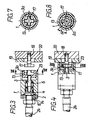
- the piston 1 and 2 consists essentially of a cylinder 1, in which a piston 4 and a piston rod 3 are slidably arranged.
- the piston rod 3 has at its one free end a head 3a, which is designed as a negative part of a bayonet coupling 12, and is firmly connected to the piston 4 at its other end .
- the piston rod 3, the piston 4 and the plate spring assembly 6 are enveloped by the cylinder 1 and the cylinder cover 2, which is fastened to the cylinder 1 by means of screws 7 and locking rings 8.
- the space 14 delimited by the piston 4 and the cylinder cover 2 can be plugged into a corresponding threaded bore 16 in the cylinder cover 2 and plug 21 (male) known in the prior art of a quick coupling 10 with a hydraulic medium, e.g. Water to be filled.
- a hydraulic medium e.g. Water to be filled.
- the other free end of the piston rod 3 with the head 3a is pressed out of the cylinder 1 by a defined amount of approximately 1 to 10 mm when the piston rod 3 is pressurized (spring-loaded cylinder in the open state).
- the action of the spring-tensioning cylinder is based on the piston installed in cylinder 1 and equipped with pre-tensioned plate spring assembly 6, on which a pressure counter to the spring force can be exerted.
- the piston rod 3 By pumping a pressurized liquid via the quick coupling 10 into the space 14 formed between the cylinder cover 2 and the piston 4, the piston rod 3 is biased by compressing the Spring assembly 6 is pushed forward together with the head 3a by a certain amount, so that the head 3a partially protrudes from the end face 23 of the cylinder 1.
- no tensile forces are transmitted from the head 3a.
- the maximum possible displacement of the piston 4 is limited by a shoulder 22, so that the spring assemblies 6 can not be set even at high hydraulic pressures.
- the spring tension cylinder is also equipped with additional sealing rings.
- the piston 4 has a piston ring 5 mounted on the jacket side; the cylinder cover 2 is also sealed by means of sealing rings 9, like the plug 21, as a positive part (male) of a quick coupling 10, a kind of snap lock, by means of sealing rings 11.
- a perfluoroelastomer which is resistant to over 300 ° C. serves as the sealing material; for the cylinder 1, the piston 4 and the piston rod 3, stainless steel is preferably used.
- a precisely defined and reproducible tensile force can be achieved.
- Typical tensile forces are around 5 to 100 kN, for which purpose pressurization with a hydraulic medium of around 100 to 500 bar is required.
- the described embodiment is characterized in particular by a short and space-saving piston rod stroke, which ensures that the plate springs 6 are not pushed together on a block when the spring tensioning cylinder is opened. As a result, the plate springs are not overloaded and their spring constant remains unchanged.
- Fig. 3 shows the state of the spring tensioning cylinder before tensioning, in which the spring tensioning cylinder is aligned so that the Maltese head 17 of the screw, the threaded shaft 18 of which is screwed into a corresponding threaded hole in the machine part 20, comes to coincide with the corresponding head 3a ( Fig. 7).
- the head 3a emerges from the cylinder 1 or its end face 23, since a hydraulic medium is pumped into the space 14 via a quick coupling or a hose 24, due to which the piston 4 and thus the piston rod 3 and the head 3a counter to the force the disc springs 6 is moved.
- the negative Maltese head 3a is pushed over the head piece 17 of the screw and then as out 8 can be seen rotated by approximately 50 °. Since the screw 17, 18 is secured with adhesive, that is to say it is fixedly attached to the machine part 20, the described rotation is brought about by rotating the entire spring-tensioning cylinder. Then the hydraulic pressure is switched off so that the plate springs 6 move the piston 4 and thus the piston rod 3 with the head 3 a in the direction of the cylinder cover 2 due to their tensioning force. As a result, the same force is exerted on the Maltese head piece 17, which ultimately causes the workpiece 19 to be pressed against the machine part 20 by the cylinder 1 or the end face 23 thereof by means of the screw 17, 18. 7 and 8 can also be seen how an overtightening of the spring tensioning cylinder by means of the stop and locking pin 13 is avoided.
- the spring-tensioning cylinder is pushed laterally onto the head piece 17 of the screw.
- the spring tensioning cylinder is slotted on one side, the slot width being allowed to have at least the outside diameter of the screw 18 and not more than the outside diameter of the head piece 17 of the screw, here a T-head screw.
- the side slit walls 25 do not run parallel, but taper towards the closed end. This facilitates the slight insertion of the screw 17, 18 into the slot 26; centering is forced. In a corresponding manner, it is also possible to chamfer the head piece 17 of the screw and / or the head 3 a.
- a non-cylindrical housing for example a housing with a rectangular cross section, can also be used in the spring-tensioning cylinder, in particular in the embodiment variants shown in FIGS. 5, 6, 9 and 10.
Landscapes
- Engineering & Computer Science (AREA)
- Mechanical Engineering (AREA)
- Moulds For Moulding Plastics Or The Like (AREA)
- Blow-Moulding Or Thermoforming Of Plastics Or The Like (AREA)
- Clamps And Clips (AREA)
Applications Claiming Priority (2)
| Application Number | Priority Date | Filing Date | Title |
|---|---|---|---|
| DE3526573 | 1985-07-25 | ||
| DE3526573 | 1985-07-25 |
Publications (2)
| Publication Number | Publication Date |
|---|---|
| EP0212047A2 true EP0212047A2 (fr) | 1987-03-04 |
| EP0212047A3 EP0212047A3 (fr) | 1989-04-26 |
Family
ID=6276701
Family Applications (1)
| Application Number | Title | Priority Date | Filing Date |
|---|---|---|---|
| EP86102706A Withdrawn EP0212047A3 (fr) | 1985-07-25 | 1986-03-01 | Vérin de serrage à ressort |
Country Status (1)
| Country | Link |
|---|---|
| EP (1) | EP0212047A3 (fr) |
Cited By (6)
| Publication number | Priority date | Publication date | Assignee | Title |
|---|---|---|---|---|
| DE8902239U1 (de) * | 1989-02-24 | 1989-04-13 | Amtec GmbH, 5000 Köln | Vorrichtung zum Festspannen von Maschinenteilen, Werkstücken, Werkzeugen o.dgl. |
| EP0374091A1 (fr) * | 1988-12-12 | 1990-06-20 | Mathys Ag Dipl. Ingenieure Eth-L | Dispositif d'abloquage pour le maintien temporaire d'un objet sur un support |
| FR2720680A1 (fr) * | 1994-06-03 | 1995-12-08 | Sidel Sa | Dispositif de fixation pour fond de moule pour une machine de fabrication de récipients à partir de préformes et machine de fabrication de récipients en plastique facilement personnalisable. |
| DE10317341B4 (de) * | 2003-04-15 | 2014-03-20 | Andreas Maier Gmbh & Co. Kg | Schnellspannzylinder mit Führungseinrichtung |
| CN109352389A (zh) * | 2018-12-07 | 2019-02-19 | 江西洪都航空工业集团有限责任公司 | 一种液压快速装夹系统 |
| US11577326B2 (en) | 2019-06-25 | 2023-02-14 | Kennametal Inc. | Sealing piston for a hydraulic expansion chucking device and expansion chucking device |
Family Cites Families (5)
| Publication number | Priority date | Publication date | Assignee | Title |
|---|---|---|---|---|
| DE1063440B (de) * | 1954-08-12 | 1959-08-13 | Wilton Tool Mfg Co Inc | Durch ein fluessiges oder gasfoermiges Druckmittel betaetigte Vorrichtung zum Aufspannen eines Werkstueckes |
| FR2087401A7 (fr) * | 1970-05-19 | 1971-12-31 | Haut Rhin Manufacture Machines | |
| CH646890A5 (de) * | 1980-10-07 | 1984-12-28 | Maag Zahnraeder & Maschinen Ag | Aufspannvorrichtung fuer ein schneidrad an einer stossmaschine. |
| DE3243991C2 (de) * | 1982-11-27 | 1985-01-10 | Karl 7298 Loßburg Hehl | Formschließeinheit mit einer Auswerfer-Antriebsvorrichtung |
| SE440618B (sv) * | 1983-04-12 | 1985-08-12 | Schedwin Sven Erik | Fastspenningsanordning, i synnerhet for fastspenning av arbetsbord, fixturer eller liknande pa ett underlag, sasom maskinbordet i en bearbetningsmaskin |
-
1986
- 1986-03-01 EP EP86102706A patent/EP0212047A3/fr not_active Withdrawn
Cited By (6)
| Publication number | Priority date | Publication date | Assignee | Title |
|---|---|---|---|---|
| EP0374091A1 (fr) * | 1988-12-12 | 1990-06-20 | Mathys Ag Dipl. Ingenieure Eth-L | Dispositif d'abloquage pour le maintien temporaire d'un objet sur un support |
| DE8902239U1 (de) * | 1989-02-24 | 1989-04-13 | Amtec GmbH, 5000 Köln | Vorrichtung zum Festspannen von Maschinenteilen, Werkstücken, Werkzeugen o.dgl. |
| FR2720680A1 (fr) * | 1994-06-03 | 1995-12-08 | Sidel Sa | Dispositif de fixation pour fond de moule pour une machine de fabrication de récipients à partir de préformes et machine de fabrication de récipients en plastique facilement personnalisable. |
| DE10317341B4 (de) * | 2003-04-15 | 2014-03-20 | Andreas Maier Gmbh & Co. Kg | Schnellspannzylinder mit Führungseinrichtung |
| CN109352389A (zh) * | 2018-12-07 | 2019-02-19 | 江西洪都航空工业集团有限责任公司 | 一种液压快速装夹系统 |
| US11577326B2 (en) | 2019-06-25 | 2023-02-14 | Kennametal Inc. | Sealing piston for a hydraulic expansion chucking device and expansion chucking device |
Also Published As
| Publication number | Publication date |
|---|---|
| EP0212047A3 (fr) | 1989-04-26 |
Similar Documents
| Publication | Publication Date | Title |
|---|---|---|
| DE3723494C2 (de) | Spannvorrichtung | |
| DE4042070C2 (de) | Druckmittelbetriebener Kraftschrauber | |
| DE1576168B2 (de) | Schaltvorrichtung fuer einen am zylinderkopf eines druckmittelbetaetigten kolbenmotors angebrachten end schalter | |
| DE60121498T2 (de) | Verfahren und Vorrichtung zum Anziehen von Schraubverbindungen | |
| EP0212047A2 (fr) | Vérin de serrage à ressort | |
| DE10142561A1 (de) | Setzgerät mit Nagelmagazin | |
| EP0846874B1 (fr) | Commutateur de cylindre | |
| WO1999054092A1 (fr) | Pince a fluide de pression | |
| DE3810388A1 (de) | Vorrichtung zum festspannen eines linear bewegbaren, langgestreckten bauteils | |
| DE2415884A1 (de) | Radialkolbenpumpe | |
| DE3518472C2 (fr) | ||
| DE3935753A1 (de) | Arretiervorrichtung | |
| DE2532330A1 (de) | Hydraulische spannelemente mit hydraulischem rueckzug | |
| EP0332839A1 (fr) | Visseur alimenté automatiquement | |
| CH700207B1 (de) | Vorrichtung zum Fixieren von Werkzeugen in Werkzeugmaschinen. | |
| DE3941752A1 (de) | Drehmomentvorrichtung | |
| EP0563821A1 (fr) | Clé hydraulique | |
| AT403379B (de) | Vorrichtung zum ankuppeln der abstechstange eines arbeitswerkzeuges einer abstechmaschine an ein spannfutter | |
| DE102004006370A1 (de) | Spannzylinder und Spannsystem zum Spannen von Wechselpaletten oder Vorrichtungen | |
| DE2103868B2 (de) | Bolzensetzgerät | |
| DE2855454A1 (de) | Druckzylindervorrichtung insbesondere zur vorspannung von bolzen-mutter- verbindungen | |
| EP0602417B1 (fr) | Vérin de travail sans tige | |
| DE10319815A1 (de) | Spannelement zum Spannen von Werkstücken auf Maschinentischen, Vorrichtungen oder Paletten | |
| DE102012020630A1 (de) | Hydraulische Ventilanordnung | |
| AT403016B (de) | Vorrichtung zum befestigen der messer auf der messerwelle eines kutters |
Legal Events
| Date | Code | Title | Description |
|---|---|---|---|
| PUAI | Public reference made under article 153(3) epc to a published international application that has entered the european phase |
Free format text: ORIGINAL CODE: 0009012 |
|
| AK | Designated contracting states |
Kind code of ref document: A2 Designated state(s): AT BE CH DE FR GB IT LI LU NL SE |
|
| PUAL | Search report despatched |
Free format text: ORIGINAL CODE: 0009013 |
|
| AK | Designated contracting states |
Kind code of ref document: A3 Designated state(s): AT BE CH DE FR GB IT LI LU NL SE |
|
| STAA | Information on the status of an ep patent application or granted ep patent |
Free format text: STATUS: THE APPLICATION IS DEEMED TO BE WITHDRAWN |
|
| 18D | Application deemed to be withdrawn |
Effective date: 19891027 |
|
| RIN1 | Information on inventor provided before grant (corrected) |
Inventor name: KREUDER, GUSTAV ADOLF, DIPL.-ING. |