EP0212112B1 - Reactor for sludge dewatering or effluent treatment - Google Patents
Reactor for sludge dewatering or effluent treatment Download PDFInfo
- Publication number
- EP0212112B1 EP0212112B1 EP86107896A EP86107896A EP0212112B1 EP 0212112 B1 EP0212112 B1 EP 0212112B1 EP 86107896 A EP86107896 A EP 86107896A EP 86107896 A EP86107896 A EP 86107896A EP 0212112 B1 EP0212112 B1 EP 0212112B1
- Authority
- EP
- European Patent Office
- Prior art keywords
- chamber
- reaction container
- container according
- reaction
- mixing
- Prior art date
- Legal status (The legal status is an assumption and is not a legal conclusion. Google has not performed a legal analysis and makes no representation as to the accuracy of the status listed.)
- Expired - Lifetime
Links
- MRVRQOWGEMMLMG-UHFFFAOYSA-N CCC1C(CN)SC(CC(C)(C)C)C1 Chemical compound CCC1C(CN)SC(CC(C)(C)C)C1 MRVRQOWGEMMLMG-UHFFFAOYSA-N 0.000 description 1
- 0 CCCC(C)*NC Chemical compound CCCC(C)*NC 0.000 description 1
Images

Classifications
-
- C—CHEMISTRY; METALLURGY
- C02—TREATMENT OF WATER, WASTE WATER, SEWAGE, OR SLUDGE
- C02F—TREATMENT OF WATER, WASTE WATER, SEWAGE, OR SLUDGE
- C02F1/00—Treatment of water, waste water, or sewage
- C02F1/52—Treatment of water, waste water, or sewage by flocculation or precipitation of suspended impurities
- C02F1/5281—Installations for water purification using chemical agents
-
- B—PERFORMING OPERATIONS; TRANSPORTING
- B01—PHYSICAL OR CHEMICAL PROCESSES OR APPARATUS IN GENERAL
- B01D—SEPARATION
- B01D21/00—Separation of suspended solid particles from liquids by sedimentation
- B01D21/0012—Settling tanks making use of filters, e.g. by floating layers of particulate material
-
- B—PERFORMING OPERATIONS; TRANSPORTING
- B01—PHYSICAL OR CHEMICAL PROCESSES OR APPARATUS IN GENERAL
- B01D—SEPARATION
- B01D21/00—Separation of suspended solid particles from liquids by sedimentation
- B01D21/0018—Separation of suspended solid particles from liquids by sedimentation provided with a pump mounted in or on a settling tank
-
- B—PERFORMING OPERATIONS; TRANSPORTING
- B01—PHYSICAL OR CHEMICAL PROCESSES OR APPARATUS IN GENERAL
- B01D—SEPARATION
- B01D21/00—Separation of suspended solid particles from liquids by sedimentation
- B01D21/0039—Settling tanks provided with contact surfaces, e.g. baffles, particles
-
- B—PERFORMING OPERATIONS; TRANSPORTING
- B01—PHYSICAL OR CHEMICAL PROCESSES OR APPARATUS IN GENERAL
- B01D—SEPARATION
- B01D21/00—Separation of suspended solid particles from liquids by sedimentation
- B01D21/0039—Settling tanks provided with contact surfaces, e.g. baffles, particles
- B01D21/0045—Plurality of essentially parallel plates
-
- B—PERFORMING OPERATIONS; TRANSPORTING
- B01—PHYSICAL OR CHEMICAL PROCESSES OR APPARATUS IN GENERAL
- B01D—SEPARATION
- B01D21/00—Separation of suspended solid particles from liquids by sedimentation
- B01D21/10—Settling tanks with multiple outlets for the separated liquids
- B01D21/16—Settling tanks with multiple outlets for the separated liquids provided with flocculating compartments
-
- B—PERFORMING OPERATIONS; TRANSPORTING
- B01—PHYSICAL OR CHEMICAL PROCESSES OR APPARATUS IN GENERAL
- B01D—SEPARATION
- B01D21/00—Separation of suspended solid particles from liquids by sedimentation
- B01D21/28—Mechanical auxiliary equipment for acceleration of sedimentation, e.g. by vibrators or the like
- B01D21/286—Means for gentle agitation for enhancing flocculation
Definitions
- the invention relates to a reaction container for sludge to be dewatered or wastewater and flocculant to be cleaned, with an inlet and an outlet opening and a reaction space for flocculation formed therebetween, and with a stirring device for mixing the flocculant with the material to be cleaned.
- Such a reaction container is known from DE-C-31 47 679.
- the solution according to the invention is characterized in that the reaction space is divided into a mixing space extending below the inlet opening with an increasing cross-section and a collecting space for the flakes extending on both sides of the mixing space, and in that the stirring device is at least one plate which oscillates in the mixing space is suspended and conveys the falling flakes on both sides into the collecting space.
- reaction vessels The general problem with such reaction vessels is that, on the one hand, thorough mixing of the sludge or wastewater with the added flocculants must be achieved in the initial stage, but with increasing flake size, because of their sensitivity to external influences, these must be treated as gently as possible in order to destroy them to prevent the flakes formed. It is therefore necessary to achieve a gradual action of the stirring device on the flake that forms.
- a line connection for returning flakes is provided between the thickening space and the mixing space.
- this line connection which causes a kind of "feedback"
- a certain part of already formed flakes is added to the incoming, to be cleaned material, so that on the one hand this stimulates the formation of flakes in the entrance area and on the other hand savings of flocculants can be achieved.
- this feedback also stabilizes the dynamic behavior of the liquid in the reaction space, in particular stabilizes the layer of mature flakes that forms at the upper end of the collecting space.
- reaction space is cubic or cuboid.
- reaction container in such a way that it can be arranged within a conventional industrial container, which results in simple transport options for the reaction container according to the invention, which can be constructed in a kit or module-like manner by connecting a plurality of identical reaction containers in series, and thereby in particular also can be used as a portable clarifier wherever the purification of waste water or sludge is required for a certain period of time.
- the stirring device designed as a plate is a perforated plate
- the hole diameter increasing downwards and the number and Hole diameters are defined according to certain physical laws.
- the hole diameter and the number of holes can be specified in particular by the person skilled in the art in such a way that excessive turbulence, i.e. Tearing-off flow conditions in the entrance area of the mixing room with the disadvantageous consequences for the formation of flakes can be avoided, since due to the increasing hole diameter towards the lower end of the mixing room there is a continuously decreasing exposure to the goods to be cleaned.
- the plate is formed over the entire area in the transition area between the mixing space and the collecting space.
- the plate is no longer used for mixing, but for generating a suitable flow from the center of the reaction space to the mixing space arranged on both sides full-surface plate at the lower end of the stirring device thus serves primarily as a "means of transport".
- the reaction container consists of a cuboid housing, in the interior of which the reaction space 10 is located.
- the reaction space 10 is divided into different functional areas by different types of baffles, the function of which will be explained in detail below, which define a specific flow path for the material to be cleaned.
- the reaction space is essentially symmetrical with respect to the longitudinal central axis BB (FIG. 2).
- BB longitudinal central axis
- a discharge pipe for the wastewater to be cleaned is arranged along the longitudinal symmetry plane to feed it into the reaction space 10.
- the material to be cleaned passes through longitudinal slots in this discharge pipe into the entrance area of the mixing space 10A which extends on both sides of the axis of symmetry.
- baffles 11 and 12 are provided in its central area, which enclose a volume with an approximately triangular cross section.
- the inner leg 11A, 12A of these guide plates 11, 12 forms with the plane of symmetry a downward opening angle of approximately 20 °, the liquid volume enclosed between these two inner legs 11A, 12A forms the mixing space 10A.
- the baffles 11, 12 also have outer legs 11B, 12B, which connect to the lower end of the inner legs 11A, 12A and extend upward to approximately the upper third of the reaction space 10 with respect to the axis of symmetry. Opposite these, further baffles 16A, 16B are provided, through which the reaction chamber receives an approximately trapezoidal cross section in its lower part.
- the volume between the outer legs 11B, 12B and these guide plates 16A, 16B forms the collecting space 10B of the reaction space 10, which is connected to the mixing space 10A in the lower third of the reaction space 10.
- the space formed by the inner leg 11A and the outer leg 11B (or 12A and 12B) forms the thickening space 10C in which the mature flakes accumulate.
- This thickening space is covered at its upper end by a cover plate 11C or 12C except for a laterally arranged inlet slot for the flakes.
- a discharge line 19A or 19B At the upper end of the thickening space 10C (between the upper end of the inner leg 11A or 12A and the upper end of the cover plate 11C or 12C) there is a discharge line 19A or 19B, the function of which is explained below.
- a sludge delivery line 15A or 15B is provided, via which the mature flakes can be drawn off.
- baffle 17A, 17B is attached, which extends obliquely downward and which serves to improve the flow conditions in the flake collecting area.
- lamella separators 10E are arranged, on the upper longitudinal sides of the reaction chamber 10 there is an overflow channel 14 for the removal of the water cleaned in the reaction chamber.
- This overflow channel 14 can continue outside the reaction chamber 10 in such a way that the water cleaned here is fed to further clarification stages downstream, such as a filter unit 20 (FIG. 1), which can be constructed in conventional technology, for example as a sand filter.
- a perforated plate 18 is suspended as a stirring device, which can be moved via a schematically illustrated eccentric drive 18A in such a way that it acts on the mixing space 10A extending between the inner legs 11A, 12A, that is to say that the mixing there located liquid volume causes.
- the perforated plate 18 has several rows of holes, the diameter of the holes increasing downwards.
- the number and the diameter of these holes in the perforated plate 18 can be calculated in such a way that those physical conditions are maintained which are necessary for thorough mixing on the one hand and for gentle flake treatment on the other hand.
- the number z of holes with the hole diameter D i of a row of holes lying at a distance r i from the pendulum axis of the perforated plate 18 is calculated as follows:
- the lower end of the stirring device is formed by a plate 18A through which the liquid is given the necessary impulse so that a flow is generated from the mixing space 10A to the collecting space 10B.
- the system works as follows: The wastewater to be cleaned passes from the discharge pipe 13 into the mixing chamber 10A, where it is gripped by the back and forth perforated plate 18 and mixed with the flocculants which are also supplied. Due to the dead weight of the flakes forming on the one hand and due to the liquid discharge in the overflow channel 14 and the discharge line 19A, 19B on the other hand, the growing flakes in the mixing space 10A sink and reach the left or right part of the collecting space 10B in the direction of the arrow, where they rise upwards and condense.
- a stationary state is formed in so far as a flake cloud forms there, from which, as a result of the suction exerted by the exhaust line 19A, 19B, the surface layer enters the thickening space through the gap remaining between the outer leg 11B and the cover plate 11C 10C arrives and is transported there from the sludge delivery line 15A or 15B to the outside. That way partially cleaned wastewater on its way to the overflow channel 14 still passes through the lamella separators 10E, where flocks may form again, which fall back onto the flock layer in the area of the deflection plate 17A, 17B.
- a circulation flow is built up in the area of the flake layer, through which those flakes which do not enter the thickening space 10C are fed back to the flake layer from below.
- This flake layer In this flake layer, compression occurs because sedimentation of flocculated suspension occurs from above and new flakes are added from below.
- This flake layer also serves as a filtration layer, the higher the concentration in the flake layer, the greater the tendency to flocculate and new flakes entering from below are absorbed as they pass through this layer until they are sucked off into the thickening space 10C.
- This flake recirculation increases the flake concentration in the area of the flake cloud (second zone), so that the plant is stable against fluctuations in the wastewater composition while at the same time reducing the consumption of chemical flocculants.
- the system according to the invention can, as shown schematically in FIG. 1, be supplemented by additional structural components, for example a dirty water reservoir 30 and a machine room 40, a space remaining below the guide plates 16A, 16B can be used as a storage space for treated waste water.
- additional structural components for example a dirty water reservoir 30 and a machine room 40, a space remaining below the guide plates 16A, 16B can be used as a storage space for treated waste water.
- the system shown in Figure 1 can be built in dimensions of an internationally standardized container (ISO form), so that it is easy to transport.
- the capacity of the reaction container according to the invention is essentially determined by its length and can therefore be easily adapted to the respective requirements.
Landscapes
- Chemical & Material Sciences (AREA)
- Chemical Kinetics & Catalysis (AREA)
- General Chemical & Material Sciences (AREA)
- Life Sciences & Earth Sciences (AREA)
- Hydrology & Water Resources (AREA)
- Engineering & Computer Science (AREA)
- Environmental & Geological Engineering (AREA)
- Water Supply & Treatment (AREA)
- Organic Chemistry (AREA)
- Separation Of Suspended Particles By Flocculating Agents (AREA)
- Treatment Of Sludge (AREA)
- Physical Or Chemical Processes And Apparatus (AREA)
Abstract
Description
Die Erfindung betrifft einen Reaktionsbehälter für zu entwässernde Schlämme oder zu reinigendes Abwasser und Flockungsmittel, mit einer Einlauf- und einer Auslauföffnung und einem dazwischen ausgebildeten Reaktionsraum zur Flockung, sowie mit einer Rühreinrichtung zur Durchmischung der Flockungsmittel mit dem zu reinigenden Gut.The invention relates to a reaction container for sludge to be dewatered or wastewater and flocculant to be cleaned, with an inlet and an outlet opening and a reaction space for flocculation formed therebetween, and with a stirring device for mixing the flocculant with the material to be cleaned.
Ein derartiger Reaktionsbehälter ist aus der DE-C-31 47 679 bekannt.Such a reaction container is known from DE-C-31 47 679.
Die erfindungsgemäße Lösung ist dadurch gekennzeichnet, daß der Reaktionsraum in einen unterhalb der Einlauföffnung sich mit nach unten zunehmendem Querschnitt erstreckenden Mischraum und einen sich beidseitig des Mischraums erstreckenden Sammelraum für die Flocken aufgeteilt ist, und daß die Rühreinrichtung mindestens eine Platte ist, die im Mischraum pendelnd aufgehängt ist und die absinkenden Flocken beidseitig in den Sammelraum fördert.The solution according to the invention is characterized in that the reaction space is divided into a mixing space extending below the inlet opening with an increasing cross-section and a collecting space for the flakes extending on both sides of the mixing space, and in that the stirring device is at least one plate which oscillates in the mixing space is suspended and conveys the falling flakes on both sides into the collecting space.
Die allgemeine Problematik bei derartigen Reaktionsbehältern besteht darin, daß einerseits im Anfangsstadium eine gründliche Durchmischung des Schlammgutes bzw. der Abwässer mit den zugegebenen Flockungsmitteln erreicht werden muß, mit zunehmender Flockengröße aber wegen deren Empfindlichkeit gegen äußere Einwirkungen diese möglichst schonend behandelt werden müssen, um eine Zerstörung der gebildeten Flocken zu verhindern. Es ist also erforderlich, eine abgestufte Einwirkung der Rühreinrichtung auf die sich bildenden Flocke zu erreichen. Durch die erfindungsgemäße Lösung wird das Flockungsmittel im Eingabebereich, also im oberen Teil des Mischraums, relativ kräftig durch die als Rühreinrichtung hin und her schwenkende Platte mit dem zu reinigenden Gut vermischt, durch den sich erweiternden Querschnitt des Mischraums wird diese Einwirkung durch die Rühreinrichtung aber immer schwächer, so daß die sich während des Absinkens bildenden Flocken einer zunehmend schonenderen Behandlung unterzogen werden, bis sie im unteren Bereich des Reaktionsraums von der Rühreinrichtung sanft in den beidseitig angeordneten Sammelraum befördert werden, wo sie in einer geeigneten Höhe abgezogen und abtransportiert werden können.The general problem with such reaction vessels is that, on the one hand, thorough mixing of the sludge or wastewater with the added flocculants must be achieved in the initial stage, but with increasing flake size, because of their sensitivity to external influences, these must be treated as gently as possible in order to destroy them to prevent the flakes formed. It is therefore necessary to achieve a gradual action of the stirring device on the flake that forms. The flocculant in the input area So in the upper part of the mixing room, relatively vigorously mixed with the material to be cleaned by the plate which swings back and forth as a stirring device, but due to the widening cross section of the mixing room, this action by the stirring device becomes weaker and weaker, so that those which form during the sinking Flakes are subjected to an increasingly gentle treatment until they are gently conveyed from the stirring device in the lower region of the reaction space into the collecting space arranged on both sides, where they can be drawn off and transported away at a suitable height.
In einer vorteilhaften Ausgestaltung der erfindungsgemäßen Lösung ist vorgesehen, die Aufteilung des Reaktionsraums durch mehrere Leitbleche vorzusehen, die so im Reaktionsbehälter aufgehängt bzw. angeordnet sind, daß Strömungsverhältnisse sich ergeben, die die oben beschriebene Einwirkung auf die Flocken bewirken, bis diese schließlich in einem durch die Leitbleche gebildeten Eindickungsraum von einer Schlammförderleitung abgezogen werden können.In an advantageous embodiment of the solution according to the invention it is provided to provide the division of the reaction space by a plurality of baffles which are suspended or arranged in the reaction vessel in such a way that flow conditions result which cause the above-described action on the flakes until they are finally in one the baffles formed by the baffles can be withdrawn from a sludge delivery line.
In einer Ausgestaltung dieser Anordnung ist vorgesehen, daß zwischen dem Eindickungsraum und dem Mischraum eine Leitungsverbindung zur Rückführung von Flocken vorgesehen ist.In one embodiment of this arrangement, it is provided that a line connection for returning flakes is provided between the thickening space and the mixing space.
Durch diese Leitungsverbindung, die eine Art "Rückkopplung" bewirkt, wird dem einfließenden, zu reinigenden Gut ein bestimmter Teil an bereits ausgebildeten Flocken zugesetzt, so daß hierdurch einerseits die Flockenbildung im Eingangsbereich angeregt wird und andererseits eine Ersparnis von Flockungsmitteln erzielt werden kann. Letztlich bewirkt diese Rückführung auch eine Stabilisierung des dynamischen Verhaltens der Flüssigkeit im Reaktionsraum, insbesondere eine Stabilisierung der am oberen Ende des Sammelraums sich bildenden Schicht von ausgereiften Flocken.Through this line connection, which causes a kind of "feedback", a certain part of already formed flakes is added to the incoming, to be cleaned material, so that on the one hand this stimulates the formation of flakes in the entrance area and on the other hand savings of flocculants can be achieved. Ultimately, this feedback also stabilizes the dynamic behavior of the liquid in the reaction space, in particular stabilizes the layer of mature flakes that forms at the upper end of the collecting space.
Weiterhin ist in vorteilhafter Weise vorgesehen, daß der Reaktionsraum kubisch oder quaderförmig ausgebildet ist.Furthermore, it is advantageously provided that the reaction space is cubic or cuboid.
Dies eröffnet die Möglichkeit, den Reaktionsbehälter so zu dimensionieren, daß er innerhalb eines üblichen Industrie-Containers angeordnet werden kann, wodurch sich einfache Transportmöglichkeiten für den erfindungsgemäßen Reaktionsbehälter ergeben, der durch Hintereinanderschaltung mehrerer gleicher Reaktionsbehälter bausatz- oder modulartig aufgebaut werden kann und dadurch insbesondere auch als transportable Klärvorrichtung überall dort eingesetzt werden kann, wo die Klärung von Abwassern oder Schlämmen für eine bestimmte Zeitspanne erforderlich ist.This opens up the possibility of dimensioning the reaction container in such a way that it can be arranged within a conventional industrial container, which results in simple transport options for the reaction container according to the invention, which can be constructed in a kit or module-like manner by connecting a plurality of identical reaction containers in series, and thereby in particular also can be used as a portable clarifier wherever the purification of waste water or sludge is required for a certain period of time.
Zur Erzielung der oben angesprochenen gründlichen Durchmischung der Abwässer mit dem Flockungsmittel einerseits und der schonenden Behandlung und Weitertransport der sich bildenden Flocken andererseits ist es besonders vorteilhaft, wenn die als Platte ausgebildete Rühreinrichtung ein Lochblech ist, wobei der Lochdurchmesser nach unten hin zunimmt und wobei Anzahl und Lochdurchmesser nach bestimmten physikalischen Gesetzmäßigkeiten definiert sind. Die Vorgabe von Lochdurchmesser und Anzahl der Löcher kann insbesondere durch den Fachmann so erfolgen, daß übermäßige Turbulenzen, d.h. abreißende Strömungsverhältnisse im Eingangsbereich des Mischraums mit den nachteiligen Folgen für die Flockenbildung vermieden werden können, da infolge des zunehmenden Lochdurchmessers zum unteren Ende des Mischraums hin eine kontinuierlich abnehmende Beaufschlagung des zu reinigenden Gutes erfolgt.In order to achieve the above-mentioned thorough mixing of the waste water with the flocculant on the one hand and the gentle treatment and further transport of the flakes which form on the other hand, it is particularly advantageous if the stirring device designed as a plate is a perforated plate, the hole diameter increasing downwards and the number and Hole diameters are defined according to certain physical laws. The hole diameter and the number of holes can be specified in particular by the person skilled in the art in such a way that excessive turbulence, i.e. Tearing-off flow conditions in the entrance area of the mixing room with the disadvantageous consequences for the formation of flakes can be avoided, since due to the increasing hole diameter towards the lower end of the mixing room there is a continuously decreasing exposure to the goods to be cleaned.
In Weiterbildung dieser Maßnahme ist vorgesehen, daß die Platte im Übergangsbereich zwischen Mischraum und Sammelraum vollflächig ausgebildet ist.In a further development of this measure it is provided that the plate is formed over the entire area in the transition area between the mixing space and the collecting space.
In diesem Bereich dient die Platte nicht mehr zur Durchmischung, sondern zur Erzeugung einer geeigneten Strömung vom Zentrum des Reaktionsraums zu dem beidseitig angeordneten Mischraum, die vollflächige Platte am unteren Ende der Rühreinrichtung dient also vorwiegend als "Transportmittel".In this area, the plate is no longer used for mixing, but for generating a suitable flow from the center of the reaction space to the mixing space arranged on both sides full-surface plate at the lower end of the stirring device thus serves primarily as a "means of transport".
Weitere vorteilhafte Ausgestaltungen der erfindungsgemäßen Lösung sind weiteren Unteransprüchen zu entnehmen.Further advantageous embodiments of the solution according to the invention can be found in further subclaims.
Ein Ausführungsbeispiel des erfindungsgemäßen Reaktionsbehälters wird nun an Zeichnungen noch erläutert, es zeigen:
- Figur 1:
- Eine perspektivische Gesamtdarstellung des Reaktionsbehälters mit angeschlossenen weiteren Klärstufen in Containerform,
- Figur 2:
- einen Querschnitt durch den Reaktionsbehälter, und
- Figur 3:
- eine schematische Darstellung der als Lochblech ausgebildeten Rühreinrichtung mit den zur Berechnung von Lochabstand und Lochdurchmesser erforderlichen Parametern.
- Figure 1:
- An overall perspective view of the reaction container with connected further clarification stages in container form,
- Figure 2:
- a cross section through the reaction vessel, and
- Figure 3:
- is a schematic representation of the stirring device designed as a perforated plate with the parameters required for calculating the hole spacing and hole diameter.
Der Reaktionsbehälter besteht aus einem quaderförmigen Gehäuse, in dessen Innenraum sich der Reaktionsraum 10 befindet. Durch verschiedenartige Leitbleche, deren Funktion weiter unten im einzelnen noch erläutert wird, ist der Reaktionsraum 10 in verschiedene Funktionsbereiche unterteilt, die einen bestimmten Strömungsweg für das zu reinigende Gut definieren. Der Reaktionsraum ist bezüglich der Längs-Mittelachse B-B (Figur 2) im wesentlichen symmetrisch aufgebaut. Im oberen zentralen Bereich ist entlang der Längssymmetrie-Ebene ein Abgaberohr für das zu reinigende Abwasser zur Zuführung desselben in den Reaktionsraum 10 angeordnet. Das zu reinigende Gut gelangt durch Längsschlitze in diesem Abgaberohr in den Eingangsbereich des beidseitig der Symmetrieachse sich erstreckenden Mischraums 10A.The reaction container consists of a cuboid housing, in the interior of which the reaction space 10 is located. The reaction space 10 is divided into different functional areas by different types of baffles, the function of which will be explained in detail below, which define a specific flow path for the material to be cleaned. The reaction space is essentially symmetrical with respect to the longitudinal central axis BB (FIG. 2). In the upper central area, a discharge pipe for the wastewater to be cleaned is arranged along the longitudinal symmetry plane to feed it into the reaction space 10. The material to be cleaned passes through longitudinal slots in this discharge pipe into the entrance area of the
Zur Unterteilung des Reaktionsraums sind in dessen mittlerem Bereich Leitbleche 11 und 12 vorgesehen, die ein Volumen mit etwa dreieckigem Querschnitt umschließen. Der innere Schenkel 11A,12A dieser Leitbleche 11,12 bildet mit der Symmetrieebene einen nach unten zeigenden Öffnungswinkel von etwa 20°, das zwischen diesen beiden inneren Schenkeln 11A,12A eingeschlossene Flüssigkeitsvolumen bildet den Mischraum 10A.In order to subdivide the reaction space, baffles 11 and 12 are provided in its central area, which enclose a volume with an approximately triangular cross section. The
Die Leitbleche 11,12 weisen außerdem äußere Schenkel 11B,12B auf, die an das untere Ende der inneren Schenkel 11A,12A anschließen und sich mit einer Neigung gegenüber der Symmetrieachse nach oben bis etwa zum oberen Drittel des Reaktionsraums 10 erstrecken. Diesen gegenüberliegend sind weitere Leitbleche 16A, 16B vorgesehen, durch die der Reaktionsraum in seinem unteren Teil einen etwa trapezförmigen Querschnitt erhält. Das Volumen zwischen den äußeren Schenkeln 11B,12B und diesen Leitblechen 16A,16B bildet den Sammelraum 10B des Reaktionsraums 10, der im unteren Drittel des Reaktionsraums 10 mit dem Mischraum 10A in Verbindung steht.The baffles 11, 12 also have outer legs 11B, 12B, which connect to the lower end of the
Der von dem inneren Schenkel 11A und dem äußeren Schenkel 11B (bzw. 12A und 12B) gebildete Raum bildet den Eindickungsraum 10C, in dem sich die ausgereiften Flocken ansammeln. Dieser Eindickungsraum ist an seinem oberen Ende durch ein Abdeckblech 11C bzw. 12C bis auf einen seitlich angeordneten Eintrittsschlitz für die Flocken abgedeckt. Am oberen Ende des Eindickungsraums 10C (zwischen dem oberen Ende des inneren Schenkels 11A bzw. 12A und dem oberen Ende des Abdeckblechs 11C bzw. 12C) ist eine Abzugsleitung 19A bzw. 19B vorgesehen, deren Funktion weiter unten erläutert wird.The space formed by the inner leg 11A and the outer leg 11B (or 12A and 12B) forms the thickening space 10C in which the mature flakes accumulate. This thickening space is covered at its upper end by a
Zwischen den unteren Enden des inneren Schenkels 11A bzw. 12A und des äußeren Schenkels 11B bzw. 12B ist eine Schlammförderleitung 15A bzw. 15B vorgesehen, über die die ausgereiften Flocken abgezogen werden können.Between the lower ends of the
Am oberen Ende des äußeren Schenkels 11B,12B ist ein Umlenkblech 17A,17B angebracht, das sich schräg nach unten erstreckt und das zur Verbesserung der Strömungsverhältnisse im Flockensammelbereich dient.At the upper end of the outer leg 11B, 12B, a
Im oberen Drittel des Reaktionsraums 10 sind Lamellenabscheider 10E angeordnet, an den oberen Längsseiten des Reaktionsraums 10 befindet sich eine Überlaufrinne 14 zum Abtransport des im Reaktionsraum gereinigten Wassers. Diese Überlaufrinne 14 kann sich außerhalb des Reaktionsraums 10 so fortsetzen, daß das hier gereinigte Wasser nachgeschalteten weiteren Klärstufen zugeführt wird, wie beispielsweise einer Filtereinheit 20 (Figur 1), die in konventioneller Technik beispielsweise als Sandfilter aufgebaut sein kann.In the upper third of the reaction chamber 10,
In der Symmetrieebene des Reaktionsraums 10 ist als Rühreinrichtung ein Lochblech 18 pendelnd aufgehängt, das über einen schematisch dargestellten Exzenterantrieb 18A derart bewegt werden kann, daß es den sich zwischen den inneren Schenkeln 11A,12A sich erstreckenden Mischraum 10A beaufschlagt, d.h., eine Durchmischung des dort befindlichen Flüssigkeitsvolumens bewirkt. Im Bereich des Mischraums 10A weist das Lochblech 18 mehrere Reihen von Löchern auf, wobei der Durchmesser der Löcher nach unten hin zunimmt.In the plane of symmetry of the reaction space 10, a
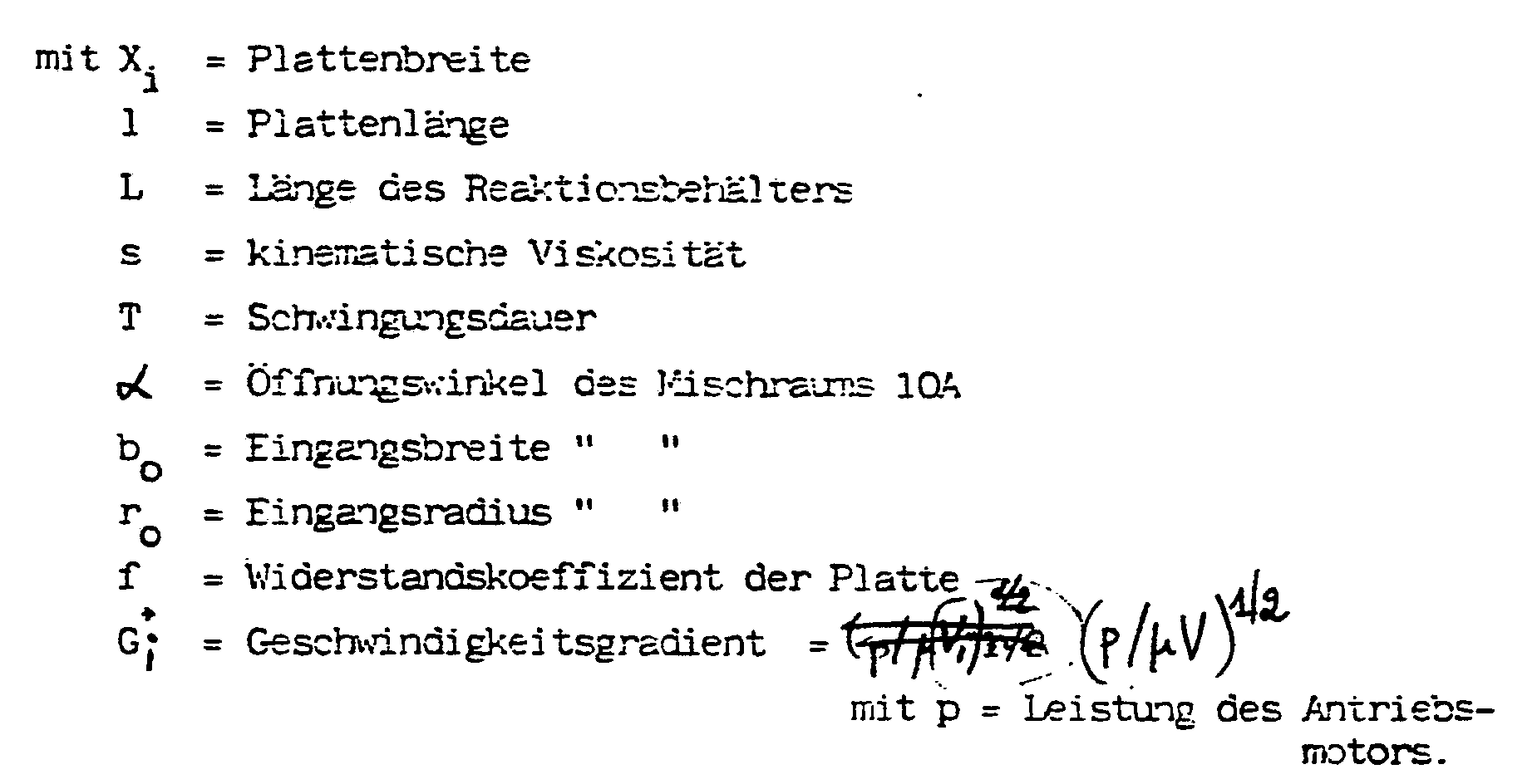
Unter Berücksichtigung der in Figur 3 angegebenen Parametern läßt sich die Anzahl und der Durchmesser dieser Löcher in der Lochplatte 18 so berechnen, daß diejenigen physikalischen Bedingungen eingehalten werden, die zur Durchmischung einerseits und zur schonenden Flockenbehandlung andererseits erforderlich sind. Die Anzahl z von Löchern mit dem Lochdurchmesser Di einer im Abstand ri von der Pendelachse des Lochblechs 18 liegenden Lochreihe berechnet sich dabei wie folgt:
Den unteren Abschluß der Rühreinrichtung bildet eine Platte 18A, durch die der Flüssigkeit der nötige Impuls vermittelt wird, damit eine Strömung aus dem Mischraum 10A zum Sammelraum 10B erzeugt wird.The lower end of the stirring device is formed by a
Die Anlage arbeitet wie folgt:
Das zu reinigende Abwasser gelangt vom Abgaberohr 13 in den Mischraum 10A, wo es von dem hin- und herpendelnden Lochblech 18 erfaßt und mit den gleichfalls zugeführten Flockungsmitteln vermischt wird. Durch das Eigengewicht der sich bildenden Flocken einerseits und durch den Flüssigkeitabzug in der Überlaufrinne 14 und der Abzugsleitung 19A,19B andererseits sinken die wachsenden Flocken im Mischraum 10A ab und gelangen in Pfeilrichtung in den linken oder rechten Teil des Sammelraums 10B, wo sie nach oben aufsteigen und sich verdichten. Im Bereich des Umlenkblechs 17A,17B bildet sich insoweit ein stationärer Zustand aus, als dort eine Flockenwolke sich bildet, von der infolge des von der Abzugsleitung 19A,19B ausgeübten Soges die Oberflächenschicht durch den zwischen äußerem Schenkel 11B und Abdeckblech 11C verbleibenden Spalt in den Eindickungsraum 10C gelangt und dort von der Schlammförderleitung 15A bzw. 15B nach außen transportiert wird. Das derart teilgegereinigte Abwasser durchläuft auf seinem Weg zur Überlaufrinne 14 noch die Lamellenabscheider 10E, wo sich gegebenenfalls erneut Flocken bilden, die von oben auf die Flockenschicht im Bereich des Umlenkbleches 17A,17B zurückfallen. Durch diese Umlenkbleche wird erzielt, daß im Bereich der Flockenschicht eine Zirkulationsströmung sich aufbaut, durch die diejenigen Flocken, die nicht in den Eindickungsraum 10C gelangen von unten wieder der Flockenschicht zugeführt werden.The system works as follows:
The wastewater to be cleaned passes from the
In dieser Flockenschicht kommt es zu einer Kompression dadurch, daß von oben eine Sedimentation geflockter Suspension erfolgt und von unten neue Flocken zugeführt werden. Dabei dient diese Flockenschicht gleichzeitig als Filtrationsschicht, je höher die Konzentration in der Flockenschicht ist, umso größer wird die Tendenz zur Flockung und neue von unten eintretende Flocken werden beim Durchgang durch diese Schicht absorbiert, bis sie in den Eindickungsraum 10C abgesaugt werden.In this flake layer, compression occurs because sedimentation of flocculated suspension occurs from above and new flakes are added from below. This flake layer also serves as a filtration layer, the higher the concentration in the flake layer, the greater the tendency to flocculate and new flakes entering from below are absorbed as they pass through this layer until they are sucked off into the thickening space 10C.
Im Bereich des Sammelraums befinden sich also von unten nach oben im wesentlichen drei verschiedene Zonen:In the area of the collecting room there are essentially three different zones from bottom to top:
In der unteren Hälfte die Schmutzwasserzone mit den darin nach oben aufsteigenden Flocken, im mittleren Bereich die Zone erhöhter Flockendichte (im Bereich der Umlenkbleche und des Überlaufs in den Eindickungsraum 10C) und im oberen Bereich bildet sich eine klare Wasserzone, in der eventuell durch die Flockenwolke durchgelangte Flocken vom Lamellenabscheider 10E aufgefangen und wieder der zweiten Zone zugeführt werden.In the lower half the dirty water zone with the flakes rising upwards, in the middle area the zone of increased flake density (in the area of the baffle plates and the overflow into the thickening space 10C) and in the upper area a clear water zone is formed, possibly through the flake cloud Flakes that have reached through are caught by the
Diese Zustände können dadurch noch weiter stabilisiert werden, indem aus dem Eindickungsraum 10C mittels einer nicht dargestellten Leitung ein Teil des eingedickten Schlammes abgeführt und mit dem zugeführten Abwasser vermischt wird, so daß diese Flocken wieder in den Eingangsbereich des Mischraumes 10A gelangen.These conditions can be further stabilized by removing part of the thickened sludge from the thickening chamber 10C by means of a line (not shown) and mixing it with the waste water supplied, so that these flakes get back into the entrance area of the
Diese Flocken-Rezirkulation erhöht die Flockenkonzentration im Bereich der Flockenwolke (zweite Zone), damit ist die Anlage stabil gegen Schwankungen in der Abwasserzusammensetzung bei gleichzeitiger Verminderung des Verbrauchs an chemischen Flockungsmitteln.This flake recirculation increases the flake concentration in the area of the flake cloud (second zone), so that the plant is stable against fluctuations in the wastewater composition while at the same time reducing the consumption of chemical flocculants.
Die erfindungsgemäße Anlage kann wie in Figur 1 schematisch dargestellt, noch durch zusätzliche Baukomponenten ergänzt werden, beispielsweise einen Schmutzwasserspeicher 30 und einen Maschinenraum 40, ein unterhalb der Leitbleche 16A,16B verbliebener Raum kann als Speicherraum für geklärtes Abwasser verwendet werden.The system according to the invention can, as shown schematically in FIG. 1, be supplemented by additional structural components, for example a dirty water reservoir 30 and a machine room 40, a space remaining below the
Die in Figur 1 dargestellte Anlage kann in Abmessungen eines international standardisierten Containers (ISO-Form) gebaut werden, so daß sie leicht transportabel ist. Die Kapazität des erfindungsgemäßen Reaktionsbehälters ist im wesentlichen durch dessen Länge bestimmt und kann auf die jeweiligen Erfordernisse dadurch einfach angepaßt werden.The system shown in Figure 1 can be built in dimensions of an internationally standardized container (ISO form), so that it is easy to transport. The capacity of the reaction container according to the invention is essentially determined by its length and can therefore be easily adapted to the respective requirements.
Claims (13)
- Reaction container for sludges, which are to be dewatered, or waste water, which is to be purified, and flocculants, including an inlet aperture and an outlet aperture and a reaction chamber provided therebetween for the flocculation process, and also including a stirring arrangement for mixing the flocculants thoroughly with the material to be purified, characterised in that the reaction chamber (10) is divided into a mixing chamber (10A), which extends beneath the inlet aperture with a downwardly increasing cross-section, and a collecting chamber (10B), which extends on each side of the mixing chamber (10A), for collecting the flocs, and in that the stirring arrangement is at least a plate which is mounted so as to oscillate in the mixing chamber (10A) and conveys the descending flocs into the collecting chamber (10B) on each side.
- Reaction container according to claim 1, characterised in that, for the separation between the mixing chamber (10A) and the collecting chamber (10B), a baffle plate (11, 12) is provided, which extends into the reaction chamber on each side of its central plane and has a V-shaped cross-section, the inner walls (11A, 12A) of said baffle plates defining the mixing chamber (10A), and the lower outer walls (11B, 12B) of said baffle plates, together with the container walls, defining the collecting chamber (10B)
- Reaction container according to claims 1 and 2, characterised in that the inlet aperture is formed by a delivery pipe (13) along an inner wall (11A) at its upper end, and the outlet aperture is formed by an overflow (14) at the upper end of the reaction container.
- Reaction container according to claims 2 and 3, characterised in that the inner portions of the baffle plates (11, 12), which are defined by their two inner walls (11A, 12A), form a thickening chamber (10C), a sludge feedpipe (15) being disposed at the base of said thickening chamber for the removal of sludge.
- Reaction container according to claims 1 to 4, characterised in that a pipe connection is provided between the thickening chamber (10C) and the mixing chamber (10A) for the return of flocs.
- Reaction container according to claim 1, characterised in that the reaction chamber (10) has a cubic or parallelepiped configuration.
- Reaction container according to claim 6, characterised in that inclinedly extending, second baffle plates (16A, 16B) are disposed in the lower half of the reaction chamber (10).
- Reaction container according to claim 2, characterised in that a deflecting plate (17A, 17B), which extends downwardly and inwardly into the collecting chamber (10B), is provided in the upper region of the outer wall (11B, 12B) of each of the baffle plates (11, 12).
- Reaction container according to claim 1, characterised in that the plate is a perforated plate (18), which is situated in the region between the inner walls (11A, 12A), and in that the diameter of the perforations increases as they extend downwardly.
- Reaction container according to claim 9, characterised in that the plate is adapted to fill the area in the transitional region between the mixing chamber (10A) and the collecting chamber (10B).
- Reaction container according to claim 9, characterised in that the diameter of the perforations is adapted to the angle of inclination of the inner walls (11A, 11B) and to the volume of the mixing chamber (10A).
- Reaction container according to claims 6 and 7, characterised in that the volume between the inclinedly extending, second baffle plates (16A, 16B) and the outer walls of the reaction container serves as a storage chamber (10D) for fresh water.
- Reaction container according to claim 11, characterised in that the number (z) and diameter (Di) of the perforations in a row of perforations, which is situated at a spacing (ri) from the oscillatory axis of the plate, are selected in accordance with the following equation:


Priority Applications (1)
| Application Number | Priority Date | Filing Date | Title |
|---|---|---|---|
| AT86107896T ATE64357T1 (en) | 1985-08-10 | 1986-06-10 | REACTION TANK FOR SLUDGE TO BE DRAINED OR WASTEWATER TO BE PURIFIED. |
Applications Claiming Priority (2)
| Application Number | Priority Date | Filing Date | Title |
|---|---|---|---|
| DE19853528783 DE3528783A1 (en) | 1985-08-10 | 1985-08-10 | REACTION CONTAINER FOR SLUDGE TO BE DRAINED OR WASTEWATER TO BE CLEANED |
| DE3528783 | 1985-08-10 |
Publications (3)
| Publication Number | Publication Date |
|---|---|
| EP0212112A2 EP0212112A2 (en) | 1987-03-04 |
| EP0212112A3 EP0212112A3 (en) | 1989-01-11 |
| EP0212112B1 true EP0212112B1 (en) | 1991-06-12 |
Family
ID=6278247
Family Applications (1)
| Application Number | Title | Priority Date | Filing Date |
|---|---|---|---|
| EP86107896A Expired - Lifetime EP0212112B1 (en) | 1985-08-10 | 1986-06-10 | Reactor for sludge dewatering or effluent treatment |
Country Status (3)
| Country | Link |
|---|---|
| EP (1) | EP0212112B1 (en) |
| AT (1) | ATE64357T1 (en) |
| DE (2) | DE3528783A1 (en) |
Families Citing this family (4)
| Publication number | Priority date | Publication date | Assignee | Title |
|---|---|---|---|---|
| FR2591215B1 (en) * | 1985-12-11 | 1990-12-07 | Omnium Traitement Valorisa | COMBINED FLOCCULATION AND WATER DECANTING TREATMENT ASSEMBLY |
| DE3739896A1 (en) * | 1987-11-25 | 1989-06-08 | Piepho Abwassertech Ralf F | Appliance for treating industrial effluents or of leachate from tips |
| CA2780724C (en) * | 2009-12-01 | 2016-06-07 | Jinmin Li | Sewage treatment apparatus with flocculation reaction chamber |
| CN120573877B (en) * | 2025-05-29 | 2026-01-09 | 内蒙古广和环境治理有限公司 | Organic industrial wastewater treatment equipment and treatment method |
Family Cites Families (2)
| Publication number | Priority date | Publication date | Assignee | Title |
|---|---|---|---|---|
| BE668629A (en) * | 1964-08-24 | 1965-12-16 | ||
| US3389892A (en) * | 1967-02-13 | 1968-06-25 | Dorr Oliver Inc | Apparatus for flocculating treatment of liquids in horizontal through-flow tanks |
-
1985
- 1985-08-10 DE DE19853528783 patent/DE3528783A1/en not_active Withdrawn
-
1986
- 1986-06-10 AT AT86107896T patent/ATE64357T1/en not_active IP Right Cessation
- 1986-06-10 DE DE8686107896T patent/DE3679738D1/en not_active Expired - Lifetime
- 1986-06-10 EP EP86107896A patent/EP0212112B1/en not_active Expired - Lifetime
Also Published As
| Publication number | Publication date |
|---|---|
| DE3528783A1 (en) | 1987-02-19 |
| DE3679738D1 (en) | 1991-07-18 |
| ATE64357T1 (en) | 1991-06-15 |
| EP0212112A2 (en) | 1987-03-04 |
| EP0212112A3 (en) | 1989-01-11 |
Similar Documents
| Publication | Publication Date | Title |
|---|---|---|
| EP0052245B1 (en) | Method and apparatus for the purification of neutralized industrial waste water | |
| DE2741574C3 (en) | Cleaning block for urban and industrial wastewater | |
| DE69007043T2 (en) | CONCENTRATION AND DRAINAGE PROCESS OF SLUDGE. | |
| DE69600998T2 (en) | METHOD AND DEVICE FOR SEPARATING NON-SOLUBLE PARTICLES FROM A LIQUID | |
| DE4143376C2 (en) | Compact system for separating and removing screenings and sand from feed channels | |
| DE1517394B2 (en) | Device for purifying water | |
| DE69500738T2 (en) | METHOD AND DEVICE FOR TREATING WATER | |
| EP0212112B1 (en) | Reactor for sludge dewatering or effluent treatment | |
| DE2517617C3 (en) | Water purification reactor | |
| DE2556995A1 (en) | MIXING CHAMBER FOR THICKENING A SUSPENSION WITH A FLOCCULATING AGENT | |
| DE2223172A1 (en) | Device for cleaning fluids by electroflotation | |
| EP0088237B1 (en) | Vibrating container for the flocculation of waste water emanating from a tumbling apparatus | |
| DE4239871C1 (en) | Device for flocculating solids from suspensions | |
| EP0053094A2 (en) | Method and device for separating particulate solid materials from their mixture with liquids, such as gases from such mixtures, and application of the method | |
| WO1992012936A1 (en) | Waste water biological treatment device | |
| DE19729802A1 (en) | Method and device for separating substances and guide device therefor | |
| WO2000026141A1 (en) | Compact installation for mechanically cleaning waste water | |
| DE2832277A1 (en) | Sewage treatment - for separate extraction of sinking, floating and suspended particles by aeration and restriction | |
| EP0951326A1 (en) | Sedimentation basin with rectangular layout for separating sludge from waste water | |
| DE3838846C2 (en) | ||
| EP3480169A1 (en) | Clarification device with precipitation module | |
| DE2936568C1 (en) | Waste water treatment device | |
| DE2440793B2 (en) | Separation device | |
| DE1658052C (en) | Device for clarifying waste water | |
| AT258819B (en) | Clarifier for water treatment by means of coagulation and filtration |
Legal Events
| Date | Code | Title | Description |
|---|---|---|---|
| PUAI | Public reference made under article 153(3) epc to a published international application that has entered the european phase |
Free format text: ORIGINAL CODE: 0009012 |
|
| AK | Designated contracting states |
Kind code of ref document: A2 Designated state(s): AT BE CH DE FR GB IT LI LU NL SE |
|
| RAP1 | Party data changed (applicant data changed or rights of an application transferred) |
Owner name: SCHNEIDER, LUDWIG, DIPL.-ING. |
|
| RIN1 | Information on inventor provided before grant (corrected) |
Inventor name: SCHNEIDER, LUDWIG, DIPL.-ING. |
|
| PUAL | Search report despatched |
Free format text: ORIGINAL CODE: 0009013 |
|
| AK | Designated contracting states |
Kind code of ref document: A3 Designated state(s): AT BE CH DE FR GB IT LI LU NL SE |
|
| 17P | Request for examination filed |
Effective date: 19890609 |
|
| 17Q | First examination report despatched |
Effective date: 19900704 |
|
| GRAA | (expected) grant |
Free format text: ORIGINAL CODE: 0009210 |
|
| AK | Designated contracting states |
Kind code of ref document: B1 Designated state(s): AT BE CH DE FR GB IT LI LU NL SE |
|
| PG25 | Lapsed in a contracting state [announced via postgrant information from national office to epo] |
Ref country code: IT Free format text: LAPSE BECAUSE OF FAILURE TO SUBMIT A TRANSLATION OF THE DESCRIPTION OR TO PAY THE FEE WITHIN THE PRE;WARNING: LAPSES OF ITALIAN PATENTS WITH EFFECTIVE DATE BEFORE 2007 MAY HAVE OCCURRED AT ANY TIME BEFORE 2007. THE CORRECT EFFECTIVE DATE MAY BE DIFFERENT FROM THE ONE RECORDED.SCRIBED TIME-LIMIT Effective date: 19910612 Ref country code: SE Effective date: 19910612 Ref country code: GB Effective date: 19910612 Ref country code: BE Effective date: 19910612 Ref country code: NL Effective date: 19910612 |
|
| REF | Corresponds to: |
Ref document number: 64357 Country of ref document: AT Date of ref document: 19910615 Kind code of ref document: T |
|
| REF | Corresponds to: |
Ref document number: 3679738 Country of ref document: DE Date of ref document: 19910718 |
|
| EN | Fr: translation not filed | ||
| PG25 | Lapsed in a contracting state [announced via postgrant information from national office to epo] |
Ref country code: FR Effective date: 19911031 |
|
| NLV1 | Nl: lapsed or annulled due to failure to fulfill the requirements of art. 29p and 29m of the patents act | ||
| GBV | Gb: ep patent (uk) treated as always having been void in accordance with gb section 77(7)/1977 [no translation filed] | ||
| PLBE | No opposition filed within time limit |
Free format text: ORIGINAL CODE: 0009261 |
|
| STAA | Information on the status of an ep patent application or granted ep patent |
Free format text: STATUS: NO OPPOSITION FILED WITHIN TIME LIMIT |
|
| 26N | No opposition filed | ||
| PG25 | Lapsed in a contracting state [announced via postgrant information from national office to epo] |
Ref country code: LU Free format text: LAPSE BECAUSE OF NON-PAYMENT OF DUE FEES Effective date: 19920630 |
|
| REG | Reference to a national code |
Ref country code: FR Ref legal event code: ST |
|
| PGFP | Annual fee paid to national office [announced via postgrant information from national office to epo] |
Ref country code: CH Payment date: 19950621 Year of fee payment: 10 |
|
| PGFP | Annual fee paid to national office [announced via postgrant information from national office to epo] |
Ref country code: AT Payment date: 19950623 Year of fee payment: 10 |
|
| PG25 | Lapsed in a contracting state [announced via postgrant information from national office to epo] |
Ref country code: AT Effective date: 19960610 |
|
| PG25 | Lapsed in a contracting state [announced via postgrant information from national office to epo] |
Ref country code: LI Effective date: 19960630 Ref country code: CH Effective date: 19960630 |
|
| REG | Reference to a national code |
Ref country code: CH Ref legal event code: PL |
|
| PGFP | Annual fee paid to national office [announced via postgrant information from national office to epo] |
Ref country code: DE Payment date: 19980202 Year of fee payment: 12 |
|
| PG25 | Lapsed in a contracting state [announced via postgrant information from national office to epo] |
Ref country code: DE Free format text: LAPSE BECAUSE OF NON-PAYMENT OF DUE FEES Effective date: 19990401 |