EP0212112B1 - Bassin pour le traitement de l'eau ou pour l'épaississement des boues - Google Patents
Bassin pour le traitement de l'eau ou pour l'épaississement des boues Download PDFInfo
- Publication number
- EP0212112B1 EP0212112B1 EP86107896A EP86107896A EP0212112B1 EP 0212112 B1 EP0212112 B1 EP 0212112B1 EP 86107896 A EP86107896 A EP 86107896A EP 86107896 A EP86107896 A EP 86107896A EP 0212112 B1 EP0212112 B1 EP 0212112B1
- Authority
- EP
- European Patent Office
- Prior art keywords
- chamber
- reaction container
- container according
- reaction
- mixing
- Prior art date
- Legal status (The legal status is an assumption and is not a legal conclusion. Google has not performed a legal analysis and makes no representation as to the accuracy of the status listed.)
- Expired - Lifetime
Links
- MRVRQOWGEMMLMG-UHFFFAOYSA-N CCC1C(CN)SC(CC(C)(C)C)C1 Chemical compound CCC1C(CN)SC(CC(C)(C)C)C1 MRVRQOWGEMMLMG-UHFFFAOYSA-N 0.000 description 1
- 0 CCCC(C)*NC Chemical compound CCCC(C)*NC 0.000 description 1
Images

Classifications
-
- C—CHEMISTRY; METALLURGY
- C02—TREATMENT OF WATER, WASTE WATER, SEWAGE, OR SLUDGE
- C02F—TREATMENT OF WATER, WASTE WATER, SEWAGE, OR SLUDGE
- C02F1/00—Treatment of water, waste water, or sewage
- C02F1/52—Treatment of water, waste water, or sewage by flocculation or precipitation of suspended impurities
- C02F1/5281—Installations for water purification using chemical agents
-
- B—PERFORMING OPERATIONS; TRANSPORTING
- B01—PHYSICAL OR CHEMICAL PROCESSES OR APPARATUS IN GENERAL
- B01D—SEPARATION
- B01D21/00—Separation of suspended solid particles from liquids by sedimentation
- B01D21/0012—Settling tanks making use of filters, e.g. by floating layers of particulate material
-
- B—PERFORMING OPERATIONS; TRANSPORTING
- B01—PHYSICAL OR CHEMICAL PROCESSES OR APPARATUS IN GENERAL
- B01D—SEPARATION
- B01D21/00—Separation of suspended solid particles from liquids by sedimentation
- B01D21/0018—Separation of suspended solid particles from liquids by sedimentation provided with a pump mounted in or on a settling tank
-
- B—PERFORMING OPERATIONS; TRANSPORTING
- B01—PHYSICAL OR CHEMICAL PROCESSES OR APPARATUS IN GENERAL
- B01D—SEPARATION
- B01D21/00—Separation of suspended solid particles from liquids by sedimentation
- B01D21/0039—Settling tanks provided with contact surfaces, e.g. baffles, particles
-
- B—PERFORMING OPERATIONS; TRANSPORTING
- B01—PHYSICAL OR CHEMICAL PROCESSES OR APPARATUS IN GENERAL
- B01D—SEPARATION
- B01D21/00—Separation of suspended solid particles from liquids by sedimentation
- B01D21/0039—Settling tanks provided with contact surfaces, e.g. baffles, particles
- B01D21/0045—Plurality of essentially parallel plates
-
- B—PERFORMING OPERATIONS; TRANSPORTING
- B01—PHYSICAL OR CHEMICAL PROCESSES OR APPARATUS IN GENERAL
- B01D—SEPARATION
- B01D21/00—Separation of suspended solid particles from liquids by sedimentation
- B01D21/10—Settling tanks with multiple outlets for the separated liquids
- B01D21/16—Settling tanks with multiple outlets for the separated liquids provided with flocculating compartments
-
- B—PERFORMING OPERATIONS; TRANSPORTING
- B01—PHYSICAL OR CHEMICAL PROCESSES OR APPARATUS IN GENERAL
- B01D—SEPARATION
- B01D21/00—Separation of suspended solid particles from liquids by sedimentation
- B01D21/28—Mechanical auxiliary equipment for acceleration of sedimentation, e.g. by vibrators or the like
- B01D21/286—Means for gentle agitation for enhancing flocculation
Definitions
- the invention relates to a reaction container for sludge to be dewatered or wastewater and flocculant to be cleaned, with an inlet and an outlet opening and a reaction space for flocculation formed therebetween, and with a stirring device for mixing the flocculant with the material to be cleaned.
- Such a reaction container is known from DE-C-31 47 679.
- the solution according to the invention is characterized in that the reaction space is divided into a mixing space extending below the inlet opening with an increasing cross-section and a collecting space for the flakes extending on both sides of the mixing space, and in that the stirring device is at least one plate which oscillates in the mixing space is suspended and conveys the falling flakes on both sides into the collecting space.
- reaction vessels The general problem with such reaction vessels is that, on the one hand, thorough mixing of the sludge or wastewater with the added flocculants must be achieved in the initial stage, but with increasing flake size, because of their sensitivity to external influences, these must be treated as gently as possible in order to destroy them to prevent the flakes formed. It is therefore necessary to achieve a gradual action of the stirring device on the flake that forms.
- a line connection for returning flakes is provided between the thickening space and the mixing space.
- this line connection which causes a kind of "feedback"
- a certain part of already formed flakes is added to the incoming, to be cleaned material, so that on the one hand this stimulates the formation of flakes in the entrance area and on the other hand savings of flocculants can be achieved.
- this feedback also stabilizes the dynamic behavior of the liquid in the reaction space, in particular stabilizes the layer of mature flakes that forms at the upper end of the collecting space.
- reaction space is cubic or cuboid.
- reaction container in such a way that it can be arranged within a conventional industrial container, which results in simple transport options for the reaction container according to the invention, which can be constructed in a kit or module-like manner by connecting a plurality of identical reaction containers in series, and thereby in particular also can be used as a portable clarifier wherever the purification of waste water or sludge is required for a certain period of time.
- the stirring device designed as a plate is a perforated plate
- the hole diameter increasing downwards and the number and Hole diameters are defined according to certain physical laws.
- the hole diameter and the number of holes can be specified in particular by the person skilled in the art in such a way that excessive turbulence, i.e. Tearing-off flow conditions in the entrance area of the mixing room with the disadvantageous consequences for the formation of flakes can be avoided, since due to the increasing hole diameter towards the lower end of the mixing room there is a continuously decreasing exposure to the goods to be cleaned.
- the plate is formed over the entire area in the transition area between the mixing space and the collecting space.
- the plate is no longer used for mixing, but for generating a suitable flow from the center of the reaction space to the mixing space arranged on both sides full-surface plate at the lower end of the stirring device thus serves primarily as a "means of transport".
- the reaction container consists of a cuboid housing, in the interior of which the reaction space 10 is located.
- the reaction space 10 is divided into different functional areas by different types of baffles, the function of which will be explained in detail below, which define a specific flow path for the material to be cleaned.
- the reaction space is essentially symmetrical with respect to the longitudinal central axis BB (FIG. 2).
- BB longitudinal central axis
- a discharge pipe for the wastewater to be cleaned is arranged along the longitudinal symmetry plane to feed it into the reaction space 10.
- the material to be cleaned passes through longitudinal slots in this discharge pipe into the entrance area of the mixing space 10A which extends on both sides of the axis of symmetry.
- baffles 11 and 12 are provided in its central area, which enclose a volume with an approximately triangular cross section.
- the inner leg 11A, 12A of these guide plates 11, 12 forms with the plane of symmetry a downward opening angle of approximately 20 °, the liquid volume enclosed between these two inner legs 11A, 12A forms the mixing space 10A.
- the baffles 11, 12 also have outer legs 11B, 12B, which connect to the lower end of the inner legs 11A, 12A and extend upward to approximately the upper third of the reaction space 10 with respect to the axis of symmetry. Opposite these, further baffles 16A, 16B are provided, through which the reaction chamber receives an approximately trapezoidal cross section in its lower part.
- the volume between the outer legs 11B, 12B and these guide plates 16A, 16B forms the collecting space 10B of the reaction space 10, which is connected to the mixing space 10A in the lower third of the reaction space 10.
- the space formed by the inner leg 11A and the outer leg 11B (or 12A and 12B) forms the thickening space 10C in which the mature flakes accumulate.
- This thickening space is covered at its upper end by a cover plate 11C or 12C except for a laterally arranged inlet slot for the flakes.
- a discharge line 19A or 19B At the upper end of the thickening space 10C (between the upper end of the inner leg 11A or 12A and the upper end of the cover plate 11C or 12C) there is a discharge line 19A or 19B, the function of which is explained below.
- a sludge delivery line 15A or 15B is provided, via which the mature flakes can be drawn off.
- baffle 17A, 17B is attached, which extends obliquely downward and which serves to improve the flow conditions in the flake collecting area.
- lamella separators 10E are arranged, on the upper longitudinal sides of the reaction chamber 10 there is an overflow channel 14 for the removal of the water cleaned in the reaction chamber.
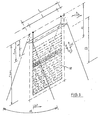
- This overflow channel 14 can continue outside the reaction chamber 10 in such a way that the water cleaned here is fed to further clarification stages downstream, such as a filter unit 20 (FIG. 1), which can be constructed in conventional technology, for example as a sand filter.
- a perforated plate 18 is suspended as a stirring device, which can be moved via a schematically illustrated eccentric drive 18A in such a way that it acts on the mixing space 10A extending between the inner legs 11A, 12A, that is to say that the mixing there located liquid volume causes.
- the perforated plate 18 has several rows of holes, the diameter of the holes increasing downwards.
- the number and the diameter of these holes in the perforated plate 18 can be calculated in such a way that those physical conditions are maintained which are necessary for thorough mixing on the one hand and for gentle flake treatment on the other hand.
- the number z of holes with the hole diameter D i of a row of holes lying at a distance r i from the pendulum axis of the perforated plate 18 is calculated as follows:
- the lower end of the stirring device is formed by a plate 18A through which the liquid is given the necessary impulse so that a flow is generated from the mixing space 10A to the collecting space 10B.
- the system works as follows: The wastewater to be cleaned passes from the discharge pipe 13 into the mixing chamber 10A, where it is gripped by the back and forth perforated plate 18 and mixed with the flocculants which are also supplied. Due to the dead weight of the flakes forming on the one hand and due to the liquid discharge in the overflow channel 14 and the discharge line 19A, 19B on the other hand, the growing flakes in the mixing space 10A sink and reach the left or right part of the collecting space 10B in the direction of the arrow, where they rise upwards and condense.
- a stationary state is formed in so far as a flake cloud forms there, from which, as a result of the suction exerted by the exhaust line 19A, 19B, the surface layer enters the thickening space through the gap remaining between the outer leg 11B and the cover plate 11C 10C arrives and is transported there from the sludge delivery line 15A or 15B to the outside. That way partially cleaned wastewater on its way to the overflow channel 14 still passes through the lamella separators 10E, where flocks may form again, which fall back onto the flock layer in the area of the deflection plate 17A, 17B.
- a circulation flow is built up in the area of the flake layer, through which those flakes which do not enter the thickening space 10C are fed back to the flake layer from below.
- This flake layer In this flake layer, compression occurs because sedimentation of flocculated suspension occurs from above and new flakes are added from below.
- This flake layer also serves as a filtration layer, the higher the concentration in the flake layer, the greater the tendency to flocculate and new flakes entering from below are absorbed as they pass through this layer until they are sucked off into the thickening space 10C.
- This flake recirculation increases the flake concentration in the area of the flake cloud (second zone), so that the plant is stable against fluctuations in the wastewater composition while at the same time reducing the consumption of chemical flocculants.
- the system according to the invention can, as shown schematically in FIG. 1, be supplemented by additional structural components, for example a dirty water reservoir 30 and a machine room 40, a space remaining below the guide plates 16A, 16B can be used as a storage space for treated waste water.
- additional structural components for example a dirty water reservoir 30 and a machine room 40, a space remaining below the guide plates 16A, 16B can be used as a storage space for treated waste water.
- the system shown in Figure 1 can be built in dimensions of an internationally standardized container (ISO form), so that it is easy to transport.
- the capacity of the reaction container according to the invention is essentially determined by its length and can therefore be easily adapted to the respective requirements.
Landscapes
- Chemical & Material Sciences (AREA)
- Chemical Kinetics & Catalysis (AREA)
- General Chemical & Material Sciences (AREA)
- Life Sciences & Earth Sciences (AREA)
- Hydrology & Water Resources (AREA)
- Engineering & Computer Science (AREA)
- Environmental & Geological Engineering (AREA)
- Water Supply & Treatment (AREA)
- Organic Chemistry (AREA)
- Separation Of Suspended Particles By Flocculating Agents (AREA)
- Treatment Of Sludge (AREA)
- Physical Or Chemical Processes And Apparatus (AREA)
Claims (13)
- Bassin pour le traitement de l'eau ou pour l'épaississement des boues et pour des floculants, avec un orifice d'admission et un orifice d'évacuation, entre lesquels est formé un compartiment réacteur pour la floculation, et avec un dispositif d'agitation pour le mélange des floculants avec le produit à traiter, caractérisé en ce que le compartiment réacteur (10) est subdivisé en un compartiment mélangeur (10A), sous-jacent à l'orifice d'admission et d'une section croissante vers le bas, et en un compartiment collecteur (10B) pour les flocons, situé de part et d'autre du compartiment mélangeur (10A), et en ce que le dispositif d'agitation se compose d'une plaque au moins, qui est suspendue et oscille dans le compartiment mélangeur (10A), et qui transporte les flocons descendants de part et d'autre, dans le compartiment collecteur (10B).
- Bassin suivant la revendication 1, caractérisé en ce qu une chicane (11, 12) d'une section en Y, dont les branches internes (11A, 12A) délimitent le compartiment mélangeur (10A), et dont les branches externes plus basses (11B, 12B) délimitent le compartiment collecteur (10B), avec les parois du bassin, est respectivement immergée dans le compartiment réacteur, de part et d'autre du plan médian de ce dernier, en vue de séparer le compartiment mélangeur (10A) et le compartiment collecteur (10B).
- Bassin suivant l'une des revendications 1 et 2, caractérisé en ce que l'orifice d'admission est formé par un tuyau de distribution (13) le long d'une branche interne (11A), sur l'extrémité supérieure de cette dernière, et en ce que l'orifice de décharge est formé par un trop-plein (14), sur l'extrémité supérieure du bassin.
- Bassin suivant l'une des revendications 2 et 3, caractérisé en ce que la partie intérieure des chicanes (11, 12), limitée par les deux branches internes (11A, 12A), forme un compartiment épaississeur (10C), à la base duquel est disposée une conduite de transport (15) pour l'extraction des boues.
- Bassin suivant les revendications 1 à 4, caractérisé en ce qu'un raccordement de conduite, pour la recirculation des flocons, est prévu entre le compartiment épaississeur (10C) et le compartiment mélangeur (10A).
- Bassin suivant la revendication 1, caractérisé en ce que le compartiment réacteur (10) est de forme cubique ou parallélépipédique.
- Bassin suivant la revendication 6, caractérisé par deux autres chicanes (16A, 16B), disposées à l'oblique dans la moitié inférieure du compartiment réacteur (10).
- Bassin suivant la revendication 2, caractérisé en ce qu'un déflecteur (17A, 17B), orienté vers le bas et vers l'intérieur du compartiment collecteur (10B), est disposé dans la zone supérieure de la branche externe (11B, 12B) des chicanes (11, 12).
- Bassin suivant la revendication 1, caractérisé en ce que la plaque est une tôle perforée (18), située dans la zone comprise entre les branches internes (11A, 12A), et en ce que le diamètre des trous augmente vers le bas.
- Bassin suivant la revendication 9, caractérisé en ce que la plaque est réalisée sur toute la surface, dans la zone de transfert entre le compartiment mélangeur (10A) et le compartiment collecteur (10B).
- Bassin suivant la revendication 9, caractérisé en ce que le diamètre des trous est adapté à l'angle d'inclinaison des branches internes (11A, 12A) et au volume du compartiment mélangeur (10A).
- Bassin suivant l'une des revendications 6 et 7, caractérisé en ce que le volume, compris entre les secondes chicanes obliques (16A, 16B) et les parois externes du bassin, sert de compartiment de stockage (10D) pour l'eau fraîche.
- Bassin suivant la revendication 11, caractérisé en ce que le nombre (z) et le diamètre des trous (Di) d'une rangée de trous, située à une distance (ri) de l'axe d'oscillation de la plaque, sont choisis suivant la relation:


Priority Applications (1)
| Application Number | Priority Date | Filing Date | Title |
|---|---|---|---|
| AT86107896T ATE64357T1 (de) | 1985-08-10 | 1986-06-10 | Reaktionsbehaelter fuer zu entwaessernde schlaemme oder zu reinigendes abwasser. |
Applications Claiming Priority (2)
| Application Number | Priority Date | Filing Date | Title |
|---|---|---|---|
| DE19853528783 DE3528783A1 (de) | 1985-08-10 | 1985-08-10 | Reaktionsbehaelter fuer zu entwaessernde schlaemme oder zu reinigendes abwasser |
| DE3528783 | 1985-08-10 |
Publications (3)
| Publication Number | Publication Date |
|---|---|
| EP0212112A2 EP0212112A2 (fr) | 1987-03-04 |
| EP0212112A3 EP0212112A3 (en) | 1989-01-11 |
| EP0212112B1 true EP0212112B1 (fr) | 1991-06-12 |
Family
ID=6278247
Family Applications (1)
| Application Number | Title | Priority Date | Filing Date |
|---|---|---|---|
| EP86107896A Expired - Lifetime EP0212112B1 (fr) | 1985-08-10 | 1986-06-10 | Bassin pour le traitement de l'eau ou pour l'épaississement des boues |
Country Status (3)
| Country | Link |
|---|---|
| EP (1) | EP0212112B1 (fr) |
| AT (1) | ATE64357T1 (fr) |
| DE (2) | DE3528783A1 (fr) |
Families Citing this family (4)
| Publication number | Priority date | Publication date | Assignee | Title |
|---|---|---|---|---|
| FR2591215B1 (fr) * | 1985-12-11 | 1990-12-07 | Omnium Traitement Valorisa | Ensemble de traitement combine de floculation et decantation des eaux |
| DE3739896A1 (de) * | 1987-11-25 | 1989-06-08 | Piepho Abwassertech Ralf F | Vorrichtung zur aufbereitung von abwaessern industrieller herkunft oder sogenannten sickerwassers aus deponien |
| CA2780724C (fr) * | 2009-12-01 | 2016-06-07 | Jinmin Li | Appareil de traitement des eaux d'egout avec chambre de reaction de floculation |
| CN120573877B (zh) * | 2025-05-29 | 2026-01-09 | 内蒙古广和环境治理有限公司 | 一种有机工业废水处理设备及处理方法 |
Family Cites Families (2)
| Publication number | Priority date | Publication date | Assignee | Title |
|---|---|---|---|---|
| BE668629A (fr) * | 1964-08-24 | 1965-12-16 | ||
| US3389892A (en) * | 1967-02-13 | 1968-06-25 | Dorr Oliver Inc | Apparatus for flocculating treatment of liquids in horizontal through-flow tanks |
-
1985
- 1985-08-10 DE DE19853528783 patent/DE3528783A1/de not_active Withdrawn
-
1986
- 1986-06-10 AT AT86107896T patent/ATE64357T1/de not_active IP Right Cessation
- 1986-06-10 DE DE8686107896T patent/DE3679738D1/de not_active Expired - Lifetime
- 1986-06-10 EP EP86107896A patent/EP0212112B1/fr not_active Expired - Lifetime
Also Published As
| Publication number | Publication date |
|---|---|
| DE3528783A1 (de) | 1987-02-19 |
| DE3679738D1 (de) | 1991-07-18 |
| ATE64357T1 (de) | 1991-06-15 |
| EP0212112A2 (fr) | 1987-03-04 |
| EP0212112A3 (en) | 1989-01-11 |
Similar Documents
| Publication | Publication Date | Title |
|---|---|---|
| EP0052245B1 (fr) | Procédé et dispositif pour l'épuration d'eaux résiduaires industrielles neutralisées | |
| DE2741574C3 (de) | Reinigungsblock für städtische und industrielle Abwässer | |
| DE69007043T2 (de) | Konzentrierungs- und entwässerungsverfahren von schlämmen. | |
| DE69600998T2 (de) | Verfahren und vorrichtung zur trennung von nicht löslichen teilchen aus einer flüssigkeit | |
| DE4143376C2 (de) | Kompaktanlage zum Abscheiden und Entfernen von Rechengut und Sand aus Zulaufgerinnen | |
| DE1517394B2 (de) | Vorrichtung zur Reinigung von Wasser | |
| DE69500738T2 (de) | Methode und vorrichtung zur behandlung von wasser | |
| EP0212112B1 (fr) | Bassin pour le traitement de l'eau ou pour l'épaississement des boues | |
| DE2517617C3 (de) | Wasserreinigungs-Reaktor | |
| DE2556995A1 (de) | Mischkammer zum eindicken einer trueben mittels eines flockungsmittels | |
| DE2223172A1 (de) | Vorrichtung zum Reinigen von Fluessigkeiten durch Elektroflotation | |
| EP0088237B1 (fr) | Récipient vibrant pour la floculation des eaux résiduelles obtenues par le traitement "au tonneau" | |
| DE4239871C1 (de) | Vorrichtung zur Flockung von Feststoffen aus Suspensionen | |
| EP0053094A2 (fr) | Procédé et dispositif pour séparer des matières particulaires solides de leur mélange avec un liquide, ainsi que des gaz de tels mélanges, et application du procédé | |
| WO1992012936A1 (fr) | Dispositif d'epuration biologique d'eaux usees | |
| DE19729802A1 (de) | Verfahren und Vorrichtung zum Trennen von Stoffen und Leiteinrichtung hierfür | |
| WO2000026141A1 (fr) | Installation compacte pour l'epuration mecanique d'eaux usees | |
| DE2832277A1 (de) | Vorrichtung zur behandlung von abwaessern | |
| EP0951326A1 (fr) | Bassin de decantation de forme rectangulaire pour la separation de la boue contenue dans des eaux usees | |
| DE3838846C2 (fr) | ||
| EP3480169A1 (fr) | Dispositif de clarification pourvu de module de précipitation | |
| DE2936568C1 (de) | Vorrichtung zur Behandlung von Abwasser | |
| DE2440793B2 (de) | Abscheidevorrichtung | |
| DE1658052C (de) | Vorrichtung zum Klaren von Abwasser | |
| AT258819B (de) | Klärapparat zur Wasseraufbereitung mittels Koagulation und Filtration |
Legal Events
| Date | Code | Title | Description |
|---|---|---|---|
| PUAI | Public reference made under article 153(3) epc to a published international application that has entered the european phase |
Free format text: ORIGINAL CODE: 0009012 |
|
| AK | Designated contracting states |
Kind code of ref document: A2 Designated state(s): AT BE CH DE FR GB IT LI LU NL SE |
|
| RAP1 | Party data changed (applicant data changed or rights of an application transferred) |
Owner name: SCHNEIDER, LUDWIG, DIPL.-ING. |
|
| RIN1 | Information on inventor provided before grant (corrected) |
Inventor name: SCHNEIDER, LUDWIG, DIPL.-ING. |
|
| PUAL | Search report despatched |
Free format text: ORIGINAL CODE: 0009013 |
|
| AK | Designated contracting states |
Kind code of ref document: A3 Designated state(s): AT BE CH DE FR GB IT LI LU NL SE |
|
| 17P | Request for examination filed |
Effective date: 19890609 |
|
| 17Q | First examination report despatched |
Effective date: 19900704 |
|
| GRAA | (expected) grant |
Free format text: ORIGINAL CODE: 0009210 |
|
| AK | Designated contracting states |
Kind code of ref document: B1 Designated state(s): AT BE CH DE FR GB IT LI LU NL SE |
|
| PG25 | Lapsed in a contracting state [announced via postgrant information from national office to epo] |
Ref country code: IT Free format text: LAPSE BECAUSE OF FAILURE TO SUBMIT A TRANSLATION OF THE DESCRIPTION OR TO PAY THE FEE WITHIN THE PRE;WARNING: LAPSES OF ITALIAN PATENTS WITH EFFECTIVE DATE BEFORE 2007 MAY HAVE OCCURRED AT ANY TIME BEFORE 2007. THE CORRECT EFFECTIVE DATE MAY BE DIFFERENT FROM THE ONE RECORDED.SCRIBED TIME-LIMIT Effective date: 19910612 Ref country code: SE Effective date: 19910612 Ref country code: GB Effective date: 19910612 Ref country code: BE Effective date: 19910612 Ref country code: NL Effective date: 19910612 |
|
| REF | Corresponds to: |
Ref document number: 64357 Country of ref document: AT Date of ref document: 19910615 Kind code of ref document: T |
|
| REF | Corresponds to: |
Ref document number: 3679738 Country of ref document: DE Date of ref document: 19910718 |
|
| EN | Fr: translation not filed | ||
| PG25 | Lapsed in a contracting state [announced via postgrant information from national office to epo] |
Ref country code: FR Effective date: 19911031 |
|
| NLV1 | Nl: lapsed or annulled due to failure to fulfill the requirements of art. 29p and 29m of the patents act | ||
| GBV | Gb: ep patent (uk) treated as always having been void in accordance with gb section 77(7)/1977 [no translation filed] | ||
| PLBE | No opposition filed within time limit |
Free format text: ORIGINAL CODE: 0009261 |
|
| STAA | Information on the status of an ep patent application or granted ep patent |
Free format text: STATUS: NO OPPOSITION FILED WITHIN TIME LIMIT |
|
| 26N | No opposition filed | ||
| PG25 | Lapsed in a contracting state [announced via postgrant information from national office to epo] |
Ref country code: LU Free format text: LAPSE BECAUSE OF NON-PAYMENT OF DUE FEES Effective date: 19920630 |
|
| REG | Reference to a national code |
Ref country code: FR Ref legal event code: ST |
|
| PGFP | Annual fee paid to national office [announced via postgrant information from national office to epo] |
Ref country code: CH Payment date: 19950621 Year of fee payment: 10 |
|
| PGFP | Annual fee paid to national office [announced via postgrant information from national office to epo] |
Ref country code: AT Payment date: 19950623 Year of fee payment: 10 |
|
| PG25 | Lapsed in a contracting state [announced via postgrant information from national office to epo] |
Ref country code: AT Effective date: 19960610 |
|
| PG25 | Lapsed in a contracting state [announced via postgrant information from national office to epo] |
Ref country code: LI Effective date: 19960630 Ref country code: CH Effective date: 19960630 |
|
| REG | Reference to a national code |
Ref country code: CH Ref legal event code: PL |
|
| PGFP | Annual fee paid to national office [announced via postgrant information from national office to epo] |
Ref country code: DE Payment date: 19980202 Year of fee payment: 12 |
|
| PG25 | Lapsed in a contracting state [announced via postgrant information from national office to epo] |
Ref country code: DE Free format text: LAPSE BECAUSE OF NON-PAYMENT OF DUE FEES Effective date: 19990401 |