EP0212298A2 - Anlage zum Sortieren von Werkstücken - Google Patents
Anlage zum Sortieren von Werkstücken Download PDFInfo
- Publication number
- EP0212298A2 EP0212298A2 EP86110073A EP86110073A EP0212298A2 EP 0212298 A2 EP0212298 A2 EP 0212298A2 EP 86110073 A EP86110073 A EP 86110073A EP 86110073 A EP86110073 A EP 86110073A EP 0212298 A2 EP0212298 A2 EP 0212298A2
- Authority
- EP
- European Patent Office
- Prior art keywords
- conveyor belt
- plant according
- workpieces
- receptacles
- processing machine
- Prior art date
- Legal status (The legal status is an assumption and is not a legal conclusion. Google has not performed a legal analysis and makes no representation as to the accuracy of the status listed.)
- Granted
Links
Images


Classifications
-
- B—PERFORMING OPERATIONS; TRANSPORTING
- B07—SEPARATING SOLIDS FROM SOLIDS; SORTING
- B07C—POSTAL SORTING; SORTING INDIVIDUAL ARTICLES, OR BULK MATERIAL FIT TO BE SORTED PIECE-MEAL, e.g. BY PICKING
- B07C5/00—Sorting according to a characteristic or feature of the articles or material being sorted, e.g. by control effected by devices which detect or measure such characteristic or feature; Sorting by manually actuated devices, e.g. switches
- B07C5/36—Sorting apparatus characterised by the means used for distribution
- B07C5/361—Processing or control devices therefor, e.g. escort memory
- B07C5/362—Separating or distributor mechanisms
-
- B—PERFORMING OPERATIONS; TRANSPORTING
- B07—SEPARATING SOLIDS FROM SOLIDS; SORTING
- B07C—POSTAL SORTING; SORTING INDIVIDUAL ARTICLES, OR BULK MATERIAL FIT TO BE SORTED PIECE-MEAL, e.g. BY PICKING
- B07C3/00—Sorting according to destination
- B07C3/02—Apparatus characterised by the means used for distribution
- B07C3/08—Apparatus characterised by the means used for distribution using arrangements of conveyors
- B07C3/082—In which the objects are carried by transport holders and the transport holders form part of the conveyor belts
-
- Y—GENERAL TAGGING OF NEW TECHNOLOGICAL DEVELOPMENTS; GENERAL TAGGING OF CROSS-SECTIONAL TECHNOLOGIES SPANNING OVER SEVERAL SECTIONS OF THE IPC; TECHNICAL SUBJECTS COVERED BY FORMER USPC CROSS-REFERENCE ART COLLECTIONS [XRACs] AND DIGESTS
- Y10—TECHNICAL SUBJECTS COVERED BY FORMER USPC
- Y10S—TECHNICAL SUBJECTS COVERED BY FORMER USPC CROSS-REFERENCE ART COLLECTIONS [XRACs] AND DIGESTS
- Y10S209/00—Classifying, separating, and assorting solids
- Y10S209/933—Accumulation receiving separated items
Definitions
- the invention relates to a system for sorting from an automatic processing machine, e.g. a hacksaw, removed workpieces, e.g. Saw sections.
- an automatic processing machine e.g. a hacksaw
- removed workpieces e.g. Saw sections.
- the invention has for its object to provide a system for sorting workpieces that continuously, i. Without interruption, the workpieces delivered by a processing machine are removed and sorted.
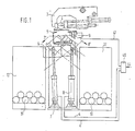
- a support table 1 is attached to the discharge side of the sawing machine (not shown), namely directly adjacent to the saw blade 2.
- a gripper 3 is attached to the support table, which places the sawing section 4 on the conveyor belt 5.
- the conveyor belt 5 has a drive 6.
- the conveyor belt 5 is a link hinge provided with a central hinge, the two sides of which can be tilted by means of tilting cylinders 7 and 8 acting on guides, whereby the saw sections along the arrows 7 'and 8' are thrown off the conveyor belt to the sides.
- the drive 6 of the conveyor belt 5 is connected via a belt or a chain to a transmitter 9 for the transport route.
- receptacles 10 to 17 are set up, which can have any dimensions, in particular can be receptacles supplied by customers.
- Another receptacle 18 is provided under the end of the conveyor belt 5.
- the sorted sawing sections 19 lie in the containers.
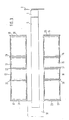
- the receiving containers 10 to 17 are arranged in compartments which are formed by dividing walls 20 to 29 which can be displaced in the direction of transport of the strip in order to adapt the compartments to the dimensions of the respectively desired receiving containers.
- Brackets 30 to 33 (FIG. 4), in which the receptacles are suspended, are attached to the partition walls.
- Baffles 34 to 37 are attached to the upper ends of the dividing walls in order to safely guide the saw sections thrown off the conveyor belt into the receptacles. Furthermore, storage rails 38 with plastic supports 39 can be attached to the upper ends of the dividing walls in order to be able to store even longer rods, the length of which exceeds the width of the available receptacle, in a sorted manner.
- a control device 40 is connected via a line 41 to the transmitter 9 and via lines 42 and 43 to the tilt cylinders 7 and 8.
- the controller is provided with data 44
- the number, dimensions and determination of the workpieces 4 and 19 and the position and dimensions of the receptacles 10 to 17 of a batch of workpieces to be machined are fed and processed by the data to timed control commands for each of the tilt cylinders 7, 8, taking into account those from the transmitter 9 route of the transport of the workpieces to be determined on the conveyor belt 5.
- the sawing machine is equipped with a control system that registers the parts to be sawn according to the client, date, number, workpiece size, etc. In addition, the dimensions of the receptacles intended for the sawn lots and their locations along the conveyor belt are stored.
- signals are sent from the data processed in the control to the measuring value transmitter 9, which then determines the distance to be covered for the conveyor belt with the workpieces of this lot.
- a saw section carried away by the processing machine has passed this distance, it is thrown off the conveyor belt, whether by tipping the conveyor belt to a certain side or in another way, for example by means of a slide.
- the distance to be covered by the saw section on the conveyor belt is determined taking into account the belt running speed so that the saw section is positioned at the discharge point in a defined position relative to the receiving container, for example with its center on the center of the receiving container.
- the saw sections must be fixed on the conveyor belt so that they cannot move in the longitudinal direction, because otherwise the registered transport route to be covered does not match the actual transport route.
- the trough-shaped design of the conveyor belt supports holding the saw section at the desired location on the conveyor belt.
- the controller Since the controller also monitors the dimensions of the saw section and the receptacle, it is ensured that the saw section that is not too long is thrown into receptacles that are too narrow.
- the system according to the invention makes it possible for the sections cut by the sawing machine to be continuously removed and sorted so that there is no jam in the sawing sections.
- the control of the sawing machines can be designed in such a way that, taking into account the number and dimensions of the sawing sections and the dimensions of the receptacles, an optimal allocation takes place, whereby in individual cases a multiple assignment of receptacles can also be provided. Furthermore, the control can also optimize the transport routes taking into account the dimensions and weight of the saw sections.
Landscapes
- Sorting Of Articles (AREA)
- Feeding Of Workpieces (AREA)
- Discharge Of Articles From Conveyors (AREA)
- Branching, Merging, And Special Transfer Between Conveyors (AREA)
Abstract
Description
- Die Erfindung betrifft eine Anlage zum Sortieren von von einer automatischen Bearbeitungsmaschine, z.B. einer Metallsäge, abgeführten Werkstücken, z.B. Sägeabschnitten.
- Zum sortierten Abführen von Sägeabschnitten von einer Metallsäge ist es bekannt, an der Abfuhrseite der Bearbeitungsmaschine einen auf Schienen geführten Wagen vorzusehen, der in vorgegebenen Abständen von der Bearbeitungsmaschine seinen Inhalt entleert. Nachteilig bei dieser Anlage ist, daß der Wagen für einen Abführvorgang eine Hin- und Herbewegung ausführen muß, also eine Leerfahrt hat.
- Der Erfindung liegt die Aufgabe zugrunde, eine Anlage zum Sortieren von Werkstücken zu schaffen, welche fortlaufend, d.h. ohne Unterbrechung, die von einer Bearbeitungsmaschine abgegebenen Werkstücke abführt und sortiert.
- Gelöst wird diese Aufgabe durch die Merkmale des Anspruchs 1. Weiterbildungen der Erfindung sind in den Unteransprüchen angegeben.
- Die Erfindung wird beispielhaft anhand der Zeichnung beschrieben, in der sind
- Fig. 1 eine Seitenansicht der Sortieranlage,
- Fig. 2 eine Vorderansicht der Anlage,
- Fig. 3 eine Draufsicht der Anlage,
- Fig. 4 eine Vorderansicht der Abteile von Aufnahmebehältern in größerem Maßstab und
- Fig. 5 eine Seitenansicht eines Abteils eines Aufnahmebehälters.
- Gemäß Fig. 1 ist an der Abfuhrseite der (nicht dargestellten) Sägemaschine ein Auflagetisch 1 angebracht, und zwar unmittelbar anliegend an das Sägeblatt 2. An dem Auflagetisch ist ein Greifer 3 angebracht, der den Sägeabschnitt 4 auf das Transportband 5 legt. Das Transportband 5 weist einen Antrieb 6 auf. Das Transportband 5 ist ein mit einem Mittelscharnier versehenes Gliederband, dessen beide Seiten mittels auf Führungen wirkenden Kippzylindern 7 und 8 abgekippt werden können, womit die Sägeabschnitte längs der Pfeile 7' und 8' von dem Transportband nach den Seiten abgeworfen werden. Der Antrieb 6 des Transportbands 5 steht über einen Riemen oder eine Kette in Verbindung mit einem Meßwertgeber 9 für die Transportstrecke.
- Beidseitig des Transportbands 5 sind Aufnahmebehälter 10 bis 17 aufgestellt, die beliebige Abmessungen aufweisen können, insbesondere von Kunden gelieferte Aufnahmebehälter sein können. Ein weiterer Aufnahmebehälter 18 ist unter dem Ende des Transportbands 5 vorgesehen. In den Behältern liegen die sortierten Sägeabschnitte 19. Die Aufnahmebehälter 10 bis 17 sind in Abteilen angeordnet, die durch Trennwände 20 bis 29 gebildet sind, die in Transportrichtung des Bandes verschiebbar sind, um die Abteile den Abmessungen der jeweils gewünschten Aufnahmebehälter anzupassen. An den Trennwänden sind Bügel 30 bis 33 (Fig. 4) angebracht, in welche die Aufnahmebehälter eingehängt werden. An den oberen Enden der Trennwände sind Leitbleche 34 bis 37 angebracht, um die von dem Transportband abgeworfenen Sägeabschnitte sicher in die Aufnahmebehälter zu führen. Des weiteren können an den oberen Enden der Trennwände Ablageschienen 38 mit Kunststoffauflagen 39 angebracht sein, um auch längere Stangen, deren Länge die Breite der verfügbaren Aufnahmebehälter übersteigt, sortiert ablegen zu können.
- Eine Steuervorrichtung 40 ist über eine Leitung 41 mit dem Meßwertgeber 9 und über Leitungen 42 und 43 mit den Kippzylindern 7 und 8 verbunden. Die Steuervorrichtung wird mit Daten 44 der Zahl, Abmessungen und Bestimmung der Werkstücke 4 bzw. 19 und der Lage und Abmessungen der Aufnahmebehälter 10 bis 17 einer zu bearbeitenden Partie von Werkstücken gespeist und verarbeitet die Daten zu zeitlich abgestimmten Steuerbefehlen für jeweils einen der Kippzylinder 7, 8 unter Berücksichtigung der von dem Meßwertgeber 9 jeweils zu ermittelnden Strecke des Transports der Werkstücke auf dem Transportband 5.
- Die Arbeitsweise der erfindungsgemäßen Anlage ist wie folgt.
- Die Sägemaschine ist mit einer Steuerung versehen, welche die zu sägenden Partien nach Auftraggeber, Termin, Zahl, Werkstückgröße etc. registriert. Darüber hinaus werden die Abmessungen der für die gesägten Partien vorgesehenen Aufnahmebehälter und ihre Standorte längs des Transportbands gespeichert. Beim Sägen einer bestimmten Partie werden aus den in der Steuerung verarbeiteten Daten Signale an den Meßwertgeber 9 gegeben, der daraufhin die für das Transportband mit den Werkstücken dieser Partie zurückzulegende Strecke festlegt. Wenn ein von der Bearbeitungsmaschine abgeführter Sägeabschnitt diese Strecke durchlaufen hat, wird er von dem Transportband abgeworfen, sei es durch Kippen des Transportbands nach einer bestimmten Seite oder auf andere Weise, beispielsweise mittels eines Schiebers abgeschoben. Dabei wird die von dem Sägeabschnitt auf dem Transportband zurückzulegende Strecke unter Berücksichtigung der Bandlaufgeschwindigkeit so festgelegt, daß der Sägeabschnitt an der Abwurfstelle in definierter Lage zum Aufnahmebehälter, z.B mit seiner Mitte auf die Mitte des Aufnahmebehälters positioniert ist.
- Die Sägeabschnitte müssen auf dem Transportband so festliegen, daß sie sich nicht in dessen Längsrichtung verschieben können, weil andernfalls die registrierte zurückzulegende Transportstrecke nicht mit der tatsächlichen Transportstrecke übereinstimmt. Die muldenförmige Ausbildung des Transportbands unterstützt das Halten des Sägeabschnitts an der gewünschten Stelle des Transportbands.
- Da die Steuerung auch die Abmessungen des Sägeabschnitts und der Aufnahmebehälter überwacht, wird sichergestellt, daß nicht zu lange Sägeabschnitt in zu schmale Aufnahmebehälter abgeworfen werden.
- Die erfindungsgemäße Anlage ermöglicht es, daß laufend die von der Sägemaschine geschnittenen Abschnitte abgeführt und sortiert abgeworfen werden, so daß kein Stau der Sägeabschnitte auftritt. Allerdings kann es auch erwünscht sein, mehrere gleiche Sägeabschnitte an einer bestimmten Stelle des Transportes ansammeln zu lassen und gemeinsam in enen Aufnahmebehälter abzuwerfen. Rest- und Schrottstücke können in dem am Ende des Transportbands angeordneten Aufnahmebehälter 18 abgeworfen werden.
- Durch die Aufhängung der Aufnahmebehälter an den Trennwänden bleibt unter den Aufnahmebehältern ein freier Raum, so daß diese nach Beendigung des Sortiervorgangs mit einem Hubwagen abtransportiert werden können.
- Die Steuerung der Sägemaschinen kann so ausgelegt werden, daß unter Berücksichtigung der Zahl und Abmessungen der Sägeabschnitte und der Abmessungen der Aufnahmebehälter eine optimale Zuordnung erfolgt, wobei im Einzelfall auch eine Mehrfachbelegung von Aufnahmebehältern vorgesehen werden kann. Des weiteren kann die Steuerung auch die Transportstrecken unter Berücksichtigung von Abmessungen und Gewicht der Sägeabschnitte optimieren.
Claims (9)
dadurch gekennzeichet, daß an der Abfuhrseite der Bearbeitungsmaschine ein endloses Transportband (5) angeordnet ist, an dessen beiden Seiten in vorgegebenen Abständen von der Bearbeitungsmaschine Aufnahmebehälter (10 bis 17) für die Werkstücke aufgestellt sind und daß eine Streckenmeßeinrichtung (9) mit dem Antrieb (6) des Transportbands in Wirkverbindung steht.
Applications Claiming Priority (2)
| Application Number | Priority Date | Filing Date | Title |
|---|---|---|---|
| DE3529149 | 1985-08-14 | ||
| DE19853529149 DE3529149A1 (de) | 1985-08-14 | 1985-08-14 | Anlage zum sortieren von werkstuecken |
Publications (3)
| Publication Number | Publication Date |
|---|---|
| EP0212298A2 true EP0212298A2 (de) | 1987-03-04 |
| EP0212298A3 EP0212298A3 (en) | 1988-01-07 |
| EP0212298B1 EP0212298B1 (de) | 1989-10-25 |
Family
ID=6278498
Family Applications (1)
| Application Number | Title | Priority Date | Filing Date |
|---|---|---|---|
| EP86110073A Expired EP0212298B1 (de) | 1985-08-14 | 1986-07-22 | Anlage zum Sortieren von Werkstücken |
Country Status (4)
| Country | Link |
|---|---|
| US (1) | US4878574A (de) |
| EP (1) | EP0212298B1 (de) |
| JP (1) | JPS6294241A (de) |
| DE (2) | DE3529149A1 (de) |
Families Citing this family (11)
| Publication number | Priority date | Publication date | Assignee | Title |
|---|---|---|---|---|
| DE3529149A1 (de) * | 1985-08-14 | 1987-02-26 | Wagner Maschf Gustav | Anlage zum sortieren von werkstuecken |
| DE3626233A1 (de) * | 1986-08-02 | 1988-02-04 | Rudolf Bueltmann | Vorrichtung zum zersaegen von langgestrecktem saegegut |
| US5025386A (en) * | 1988-08-01 | 1991-06-18 | Pavo Pusic | Automated mail collecting and telecommunication machine II |
| CA2033083C (en) * | 1989-05-19 | 1999-07-20 | Toru Tokiwa | Cut sections conveying device for a cutting machine |
| DE4090853T1 (de) * | 1989-05-19 | 1991-04-25 | Amada Co | Schnitteilstueck-transportvorrichtung fuer eine schneidemaschine |
| JP2510365Y2 (ja) * | 1990-04-23 | 1996-09-11 | 三菱重工業株式会社 | 数値制御多軸自動盤 |
| CA2022289A1 (en) * | 1990-07-30 | 1992-01-31 | Karl Hartlepp | Sorting machine |
| WO2014136764A1 (ja) * | 2013-03-08 | 2014-09-12 | 日本発條株式会社 | 旋盤装置用の回収機構および回収機構の制御方法 |
| CN103506330B (zh) * | 2013-10-09 | 2015-10-28 | 中江县凯讯电子有限公司 | 用于网络变压器检测机的分组装置 |
| CN110510381B (zh) * | 2019-07-16 | 2021-06-01 | 武钢资源集团有限公司 | 矿用机车可升降式挡板装置 |
| CN115254670B (zh) * | 2022-08-05 | 2023-04-07 | 东莞市技师学院(东莞市高级技工学校) | 一种基于红外感应的冷链运输系统及监测设备 |
Family Cites Families (19)
| Publication number | Priority date | Publication date | Assignee | Title |
|---|---|---|---|---|
| US974720A (en) * | 1910-03-10 | 1910-11-01 | Isaac A Holeman | Orange-sizing machine. |
| US997468A (en) * | 1910-03-31 | 1911-07-11 | George D Parker | Fruit sizer or grader. |
| US2194381A (en) * | 1937-01-26 | 1940-03-19 | Sovex Ltd | Sorting apparatus |
| DE800839C (de) * | 1948-10-02 | 1950-12-11 | Natronzellstoff Und Papierfabr | Gliederfoerderband mit Entladungsmoeglichkeit an einer oder mehreren Stellen |
| US3116835A (en) * | 1959-10-14 | 1964-01-07 | Theodore A Brandon | Lumber sorting and accumulating mechanisms |
| US2998889A (en) * | 1960-08-05 | 1961-09-05 | Stewart Warner Corp | Synchronous pulse generator and drive |
| FR1351699A (fr) * | 1963-02-16 | 1964-02-07 | Electrolux Ab | Installation d'emmagasinage ou de triage |
| GB1022630A (en) * | 1963-06-24 | 1966-03-16 | J H Schmitz Sohne G M B H | Improvements in conveyors |
| US3242342A (en) * | 1964-02-24 | 1966-03-22 | Fmc Corp | Means for locating the center of a moving article |
| US3348678A (en) * | 1966-01-10 | 1967-10-24 | Stanley L Flowers | Automatic weight grading apparatus |
| US3469690A (en) * | 1967-07-28 | 1969-09-30 | Terleco Inc | Method and means for sorting objects according to length |
| SE370872B (de) * | 1972-06-07 | 1974-11-04 | Msa Medicinska Servosyst Ab | |
| US3837453A (en) * | 1973-01-15 | 1974-09-24 | Morgan Construction Co | Material handling apparatus |
| US4024948A (en) * | 1973-08-31 | 1977-05-24 | Jan Persson | Conveyor track apparatus for logs |
| US3955678A (en) * | 1974-08-09 | 1976-05-11 | American Chain & Cable Company, Inc. | Sorting system |
| US4016979A (en) * | 1975-09-18 | 1977-04-12 | Bibler Brother, Inc. | Log sorting conveyor |
| DE3148539C2 (de) * | 1981-12-08 | 1983-12-08 | Ransburg-Gema AG, 9015 St.Gallen | Sprühbeschichtungsanlage |
| DE8409588U1 (de) * | 1984-03-26 | 1984-08-09 | Klein, Paul, Ing.(grad.), 3006 Burgwedel | Werkzeugmaschine |
| DE3529149A1 (de) * | 1985-08-14 | 1987-02-26 | Wagner Maschf Gustav | Anlage zum sortieren von werkstuecken |
-
1985
- 1985-08-14 DE DE19853529149 patent/DE3529149A1/de not_active Ceased
-
1986
- 1986-07-22 DE DE8686110073T patent/DE3666571D1/de not_active Expired
- 1986-07-22 EP EP86110073A patent/EP0212298B1/de not_active Expired
- 1986-08-13 JP JP61191164A patent/JPS6294241A/ja active Pending
-
1988
- 1988-02-16 US US07/156,209 patent/US4878574A/en not_active Expired - Fee Related
Also Published As
| Publication number | Publication date |
|---|---|
| DE3529149A1 (de) | 1987-02-26 |
| JPS6294241A (ja) | 1987-04-30 |
| EP0212298B1 (de) | 1989-10-25 |
| US4878574A (en) | 1989-11-07 |
| DE3666571D1 (en) | 1989-11-30 |
| EP0212298A3 (en) | 1988-01-07 |
Similar Documents
| Publication | Publication Date | Title |
|---|---|---|
| EP3254893B1 (de) | Zustellfahrzeug und verfahren zur zustellung von sendungen an unterschiedlichen orten einer zustellroute | |
| DE4015935C2 (de) | Kommissioniervorrichtung für Artikel | |
| EP1100629B1 (de) | Vorrichtung zum entleeren von sendungsbehältern | |
| DE112006001872B4 (de) | Kommissionierverfahren sowie Kommissionierfördervorrichtung für ein Lager | |
| DE2803884C2 (de) | Einrichtung zur Abgabe und Verteilung von Gegenständen | |
| EP1352856B1 (de) | Verfahren zur automatisierten Gruppierung von Objekten | |
| DE10136354A1 (de) | Verfahren und Anlage zum Kommissionieren mit einem Behälterregal und zugeordnetem Regalbediengerät | |
| EP0212298B1 (de) | Anlage zum Sortieren von Werkstücken | |
| EP0392308B1 (de) | Einrichtung zum programmgesteuerten Buntaufteilen von Werkstückplatten | |
| DE102021102385A1 (de) | Einlege-Zufuhreinheit sowie Verfahren für ihren Betrieb | |
| EP1125684B2 (de) | Verkettetes Fertigungssystem | |
| CH702772B1 (de) | Verfahren zum Schneiden von Materialtafeln, insbesondere Metallblechen, sowie Schneidanlage zur Durchführung des Verfahrens. | |
| DE3716666C2 (de) | Plattenaufteilanlage mit einer Längssäge und einer Quersäge | |
| EP1498349A1 (de) | Verfahren und Vorrichtung zur Frühgepäckspeicherung | |
| EP1322537B1 (de) | Stoffeingabe einer sendungssortieranlage und verfahren zum beladen der stoffeingabe | |
| EP0242588B1 (de) | Transport- und Sortiervorrichtung für eine rechnergesteuerte Winkelschere | |
| DE69104589T2 (de) | Dynamische Speichervorrichtung für Behälter in einer pneumatisch betriebenen Transferstrasse. | |
| WO2007121697A1 (de) | Fertigungssystem mit verkettung von bearbeitungsstationen über ein hochgelegtes transfermodul | |
| DE2704230A1 (de) | Vorrichtung zum zufuehren von bewehrungsstaeben | |
| DE4218161B4 (de) | Handhabungssystem für Stangenmaterial, insbesondere zum Beschicken einer Bearbeitungsmaschine und Verfahren zum Handhaben von Stangenmaterial mit einem Handhabungsgerät | |
| EP0281955A2 (de) | Langmateriallagereinrichtung | |
| DE4240158C1 (de) | Sortieranlagenabgangsvorrichtung | |
| DE10019632A1 (de) | Transportanordnung für ein Warenlager | |
| DE3300939C1 (de) | Betonstahlverarbeitungsanlage | |
| DE19617818A1 (de) | Kompaktsägewerk |
Legal Events
| Date | Code | Title | Description |
|---|---|---|---|
| PUAI | Public reference made under article 153(3) epc to a published international application that has entered the european phase |
Free format text: ORIGINAL CODE: 0009012 |
|
| AK | Designated contracting states |
Kind code of ref document: A2 Designated state(s): CH DE FR GB IT LI |
|
| PUAL | Search report despatched |
Free format text: ORIGINAL CODE: 0009013 |
|
| AK | Designated contracting states |
Kind code of ref document: A3 Designated state(s): CH DE FR GB IT LI |
|
| 17P | Request for examination filed |
Effective date: 19880204 |
|
| 17Q | First examination report despatched |
Effective date: 19880613 |
|
| GRAA | (expected) grant |
Free format text: ORIGINAL CODE: 0009210 |
|
| ITF | It: translation for a ep patent filed | ||
| AK | Designated contracting states |
Kind code of ref document: B1 Designated state(s): CH DE FR GB IT LI |
|
| GBT | Gb: translation of ep patent filed (gb section 77(6)(a)/1977) | ||
| ET | Fr: translation filed | ||
| REF | Corresponds to: |
Ref document number: 3666571 Country of ref document: DE Date of ref document: 19891130 |
|
| PLBE | No opposition filed within time limit |
Free format text: ORIGINAL CODE: 0009261 |
|
| STAA | Information on the status of an ep patent application or granted ep patent |
Free format text: STATUS: NO OPPOSITION FILED WITHIN TIME LIMIT |
|
| 26N | No opposition filed | ||
| ITTA | It: last paid annual fee | ||
| PGFP | Annual fee paid to national office [announced via postgrant information from national office to epo] |
Ref country code: FR Payment date: 19930709 Year of fee payment: 8 |
|
| PGFP | Annual fee paid to national office [announced via postgrant information from national office to epo] |
Ref country code: GB Payment date: 19930712 Year of fee payment: 8 |
|
| PGFP | Annual fee paid to national office [announced via postgrant information from national office to epo] |
Ref country code: CH Payment date: 19930726 Year of fee payment: 8 |
|
| PGFP | Annual fee paid to national office [announced via postgrant information from national office to epo] |
Ref country code: DE Payment date: 19930830 Year of fee payment: 8 |
|
| PG25 | Lapsed in a contracting state [announced via postgrant information from national office to epo] |
Ref country code: GB Effective date: 19940722 |
|
| PG25 | Lapsed in a contracting state [announced via postgrant information from national office to epo] |
Ref country code: LI Effective date: 19940731 Ref country code: CH Effective date: 19940731 |
|
| GBPC | Gb: european patent ceased through non-payment of renewal fee |
Effective date: 19940722 |
|
| PG25 | Lapsed in a contracting state [announced via postgrant information from national office to epo] |
Ref country code: FR Effective date: 19950331 |
|
| REG | Reference to a national code |
Ref country code: CH Ref legal event code: PL |
|
| PG25 | Lapsed in a contracting state [announced via postgrant information from national office to epo] |
Ref country code: DE Effective date: 19950401 |
|
| REG | Reference to a national code |
Ref country code: FR Ref legal event code: ST |
|
| PG25 | Lapsed in a contracting state [announced via postgrant information from national office to epo] |
Ref country code: IT Free format text: LAPSE BECAUSE OF NON-PAYMENT OF DUE FEES;WARNING: LAPSES OF ITALIAN PATENTS WITH EFFECTIVE DATE BEFORE 2007 MAY HAVE OCCURRED AT ANY TIME BEFORE 2007. THE CORRECT EFFECTIVE DATE MAY BE DIFFERENT FROM THE ONE RECORDED. Effective date: 20050722 |