EP0212315A2 - Méthode et dispositif pour fixer des éléments de support, de liaison ou d'articulation sur des panneaux ou blocs de polystyrène expansé ou similaire - Google Patents
Méthode et dispositif pour fixer des éléments de support, de liaison ou d'articulation sur des panneaux ou blocs de polystyrène expansé ou similaire Download PDFInfo
- Publication number
- EP0212315A2 EP0212315A2 EP86110189A EP86110189A EP0212315A2 EP 0212315 A2 EP0212315 A2 EP 0212315A2 EP 86110189 A EP86110189 A EP 86110189A EP 86110189 A EP86110189 A EP 86110189A EP 0212315 A2 EP0212315 A2 EP 0212315A2
- Authority
- EP
- European Patent Office
- Prior art keywords
- plates
- plate
- nails
- panels
- face
- Prior art date
- Legal status (The legal status is an assumption and is not a legal conclusion. Google has not performed a legal analysis and makes no representation as to the accuracy of the status listed.)
- Withdrawn
Links
- 238000000034 method Methods 0.000 title claims abstract description 10
- 239000004794 expanded polystyrene Substances 0.000 title claims description 14
- 239000000463 material Substances 0.000 claims description 7
- 239000002991 molded plastic Substances 0.000 claims description 2
- 238000003780 insertion Methods 0.000 claims 1
- 230000037431 insertion Effects 0.000 claims 1
- 238000000465 moulding Methods 0.000 claims 1
- 239000004793 Polystyrene Substances 0.000 abstract description 14
- 229920002223 polystyrene Polymers 0.000 abstract description 14
- XAGFODPZIPBFFR-UHFFFAOYSA-N aluminium Chemical compound [Al] XAGFODPZIPBFFR-UHFFFAOYSA-N 0.000 description 2
- 229910052782 aluminium Inorganic materials 0.000 description 2
- 239000004411 aluminium Substances 0.000 description 2
- 238000005520 cutting process Methods 0.000 description 2
- 238000004519 manufacturing process Methods 0.000 description 2
- 239000000470 constituent Substances 0.000 description 1
- 238000010276 construction Methods 0.000 description 1
- 238000000605 extraction Methods 0.000 description 1
- 238000001125 extrusion Methods 0.000 description 1
- 239000003292 glue Substances 0.000 description 1
- 230000013011 mating Effects 0.000 description 1
- 238000010137 moulding (plastic) Methods 0.000 description 1
- 230000035515 penetration Effects 0.000 description 1
- 239000004033 plastic Substances 0.000 description 1
- 238000003860 storage Methods 0.000 description 1
Images



Classifications
-
- F—MECHANICAL ENGINEERING; LIGHTING; HEATING; WEAPONS; BLASTING
- F16—ENGINEERING ELEMENTS AND UNITS; GENERAL MEASURES FOR PRODUCING AND MAINTAINING EFFECTIVE FUNCTIONING OF MACHINES OR INSTALLATIONS; THERMAL INSULATION IN GENERAL
- F16B—DEVICES FOR FASTENING OR SECURING CONSTRUCTIONAL ELEMENTS OR MACHINE PARTS TOGETHER, e.g. NAILS, BOLTS, CIRCLIPS, CLAMPS, CLIPS OR WEDGES; JOINTS OR JOINTING
- F16B15/00—Nails; Staples
- F16B15/0023—Nail plates
- F16B15/0053—Nail plates with separate nails attached to the plate
-
- E—FIXED CONSTRUCTIONS
- E05—LOCKS; KEYS; WINDOW OR DOOR FITTINGS; SAFES
- E05D—HINGES OR SUSPENSION DEVICES FOR DOORS, WINDOWS OR WINGS
- E05D5/00—Construction of single parts, e.g. the parts for attachment
- E05D5/02—Parts for attachment, e.g. flaps
- E05D5/04—Flat flaps
-
- F—MECHANICAL ENGINEERING; LIGHTING; HEATING; WEAPONS; BLASTING
- F16—ENGINEERING ELEMENTS AND UNITS; GENERAL MEASURES FOR PRODUCING AND MAINTAINING EFFECTIVE FUNCTIONING OF MACHINES OR INSTALLATIONS; THERMAL INSULATION IN GENERAL
- F16B—DEVICES FOR FASTENING OR SECURING CONSTRUCTIONAL ELEMENTS OR MACHINE PARTS TOGETHER, e.g. NAILS, BOLTS, CIRCLIPS, CLAMPS, CLIPS OR WEDGES; JOINTS OR JOINTING
- F16B15/00—Nails; Staples
- F16B15/0023—Nail plates
- F16B2015/0061—Multipiece-plates
-
- F—MECHANICAL ENGINEERING; LIGHTING; HEATING; WEAPONS; BLASTING
- F16—ENGINEERING ELEMENTS AND UNITS; GENERAL MEASURES FOR PRODUCING AND MAINTAINING EFFECTIVE FUNCTIONING OF MACHINES OR INSTALLATIONS; THERMAL INSULATION IN GENERAL
- F16B—DEVICES FOR FASTENING OR SECURING CONSTRUCTIONAL ELEMENTS OR MACHINE PARTS TOGETHER, e.g. NAILS, BOLTS, CIRCLIPS, CLAMPS, CLIPS OR WEDGES; JOINTS OR JOINTING
- F16B15/00—Nails; Staples
- F16B15/0023—Nail plates
- F16B2015/0076—Nail plates with provisions for additional fastening means, e.g. hooks, holes for separate screws or nails, adhesive
-
- F—MECHANICAL ENGINEERING; LIGHTING; HEATING; WEAPONS; BLASTING
- F16—ENGINEERING ELEMENTS AND UNITS; GENERAL MEASURES FOR PRODUCING AND MAINTAINING EFFECTIVE FUNCTIONING OF MACHINES OR INSTALLATIONS; THERMAL INSULATION IN GENERAL
- F16B—DEVICES FOR FASTENING OR SECURING CONSTRUCTIONAL ELEMENTS OR MACHINE PARTS TOGETHER, e.g. NAILS, BOLTS, CIRCLIPS, CLAMPS, CLIPS OR WEDGES; JOINTS OR JOINTING
- F16B2200/00—Constructional details of connections not covered for in other groups of this subclass
- F16B2200/67—Rigid angle couplings
-
- Y—GENERAL TAGGING OF NEW TECHNOLOGICAL DEVELOPMENTS; GENERAL TAGGING OF CROSS-SECTIONAL TECHNOLOGIES SPANNING OVER SEVERAL SECTIONS OF THE IPC; TECHNICAL SUBJECTS COVERED BY FORMER USPC CROSS-REFERENCE ART COLLECTIONS [XRACs] AND DIGESTS
- Y10—TECHNICAL SUBJECTS COVERED BY FORMER USPC
- Y10T—TECHNICAL SUBJECTS COVERED BY FORMER US CLASSIFICATION
- Y10T403/00—Joints and connections
- Y10T403/49—Member deformed in situ
- Y10T403/4974—Member deformed in situ by piercing
Definitions
- the present invention concerns a method and a device for carrying-out the same, to fix in a removable way support, joint and hinge elements to panels and blocks of expanded polystyrene or similar materials.
- polystyrene panels have a very low density and for this reason are extremely difficult to fix together in removable way. Precisely because of their low density, the panels of expanded polystyrene offer little resistance to the penetration of nails or similar fixings which then have little resistance to their extraction. Further, even quite small loads applied perpendicularly to the nail tend to deform the polystyrene with consequent reduction of its ability to hold the same nail.
- expanded polystyrene Due to their lightness and ease of handling, and the surface characteristics, expanded polystyrene, especially in panels, is often used in photography to make background walls and light reflecting screens.
- the panels In general the panels have to be arranged vertically and often have to be superimposed upright to form determined angles.
- the main object of the present invention is to provide a method and a device for fixing in a removable way support, joint, and hinge elements to panels of expanded polystyrene, in such a manner to overcome the above mentioned problems.
- a further object of this invention is to provide a series of devices which allow the rapid fixing together, in a stable way and in any desired position and angle, two or more panels of expanded polystyrene or an equivalent material.
- Another object aim of the invention is to provide a device for supporting a panel of expanded polystyrene in a vertical or angled position.
- the device for carrying-out the method according to the invention is characterized in that it comprises of a pair of plates, each having a face from which protrude perpendicularly one or more nails.
- at least one of the plates has means for locking on to the other plate so that the two plates are kept locked together when they are in the inserted position.
- the device comprises essentially a pair of plates 1 and 2, of which one is bent at right angles 2. Both the plates present a number of nails 3 perpendicular to their faces.
- the nails of plate 2 protrude from one of the two faces (indicated by 4 in the figure) in such a way as to be turned towards the interior of the angle formed by the latter.
- the other face 5 of plate 2 presents a number of through holes 6 positioned to coincide with the nails protruding from plate 1.
- the device is attached to a panel of polystyrene 7 in such a way as the nails 3 penetrate the panel until they bring face 4 into contact with the surface of the panel itself.
- the plate 2 is attached to the panel with its face 4 in contact with the lower edge 8 of the panel and with its face 5 in contact with the side of the same panel.
- plate 1 is inserted into the panel so taht the nails 3 pass into holes 6 of plate 2 until the two plates are in contact.
- the bearing of plate 1 on the vertical face of plate 2 ensures that the plates and the nails are kept perpendicular to each other.
- retainers 9 on the mating faces which could be for example strips of velcro, snap fasteners or the like.
- the two faces of plate 2 can be of differing lengths, in particular face 5 could be divided into more angular elements protruding perpendicularly from face 4 which could have one or more centring holes through which are inserted one or more nails from plate 1 or one or more pins or other centring elements protruding from the latter plate.
- the device 1 could be used to connect two panels together in line or to attach something to a panel.
- face 4 of plate 2 could be turned at right angles or any other angle to link two panels at an angle to each other.
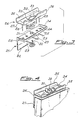
- the second embodiment of the device is comprised essentially of a first plate 21 and a face 22 from which protrude perpendicularly a number of long pointed elements 23 and a face or angled elements 24 presenting a number of through holes 25; a second plate 26 presents a face 27 from which protrude perpendicularly a number of long pointed elements 28 so diposed to locate in the holes 25 of the angled element 24 of the first plate 21.
- Both plates 21 and 26 are in moulded plastic and the related long pointed elements 22 and 28 are in one piece, slightly conical and have-cross shaped or similar cross-section.
- the angular element 24 protruding from plate 21 is comprised, apart from the through holes 25, of a through hole 29 which takes a support pin 30 carrying a small wing nut 31.
- the pin 30 has an enlarged base and is inserted into the hole 29 of the angular element 24 in such a way as to protrude towards the outside of the latter.
- the wing nut 31 is snap fitted onto the head of the pin 30 and is thus linked to plate 21.
- the plate 26 has a central through hole 32 so shaped to take the wing nut 31 when the latter is in the horizontal position; in this way when plates 21 and 26 are correctly positioned with the long protruding elements of plate 26 engaged in the holes of plate 21, a halfturn of the wing nut clockwise or anticlockwise will lock the plates together. (figure 4)
- the angular element 24 protruding from plate 21 presents a perimeter webbing which strengthens it and ensures correct positioning with respect to plate 21.
- the plate 26 presents, in the part opposite the long elements 28, a pair of lugs 35 which facilitate manual fitting together.
- the production of the plates as a plastic moulding allows the production of a single structure 36 comprising of two plates 21 hinged together symmetrically so that the elements 24 are opposite each other and protruding in the same direction.
- the plates 21 are hinged on the edge opposite the angluar element 24 and the hinge 37 consists of a section of plastic which is thinner than that of face 22.
- the structure 36 is moulded as a single unit and the plates 21 can be easily separated by cutting the hinge 37 which joins them.
- the structure 36 can be used in combination with plates 26 to hinge together two polystyrene blocks or panels as illustrated in figure 6.
- the device comprises two pairs of plates 41, 42, 43 and 44 all similar to the pair of plates in figs. 1 and 2.
- the two right angled plates are hinged together at an edge so that the faces 4 carrying the nails 3 rotate in the same plane.
- the two pairs of plates are fixed corresponding to the two lower inside edges of two expanded polystyrene panels 7 placed side by side. It should be noted that the two panels, once locked together by the device in figure 7, can be stood upright by simply angling them, without any further means of support.
- the device can also be used to overlap two panels so that they form a variable angle with each other.
- an arm 46 is hinged, rotating in the same plane as the plates 41 and 43.
- a plate 48 having one or more nails 49 turned in the same direction as those on the plates 41 and 43.
- the plate 21 can be substituted by a drawn aluminium section 58 or any other material with the same cross-section and longer length.
- the drawn section 58 presents a series of long pointed elements 59 (for example, rivets) similar to those 23 presented by plate 21 and a series of through holes 60 to take the long pointed elements 28 protruding from plate 26.
- the wing nut 31 could easily be attached to the drawn section 58 to fix plate 26 to it. In this way the drawn section 58 can be attached to a panel or block of expanded polystyrene in exactly the same way as plate 21.
- Accessories can be added to the drawn section 58, such as an element 61 to regulate the inclination of two panels hinged together by one or more structures 26, (see figure 9) or a support 62 for supporting a panel in the vertical position (see figure 10).
- the support 62 can be very advantageously made from Polionda (registered trade mark) which is an extrusion in PVC composed of a sandwich of two lamina separated by a number of parallel lamine laid side by side. This material can be very easily bent by cutting one of the two lamina parallel to the side by side lamina.
- Polionda registered trade mark
- a drawn section 58 of aluminium with the same characteristics as that indicated with the same number in figure 8, is attached to an expanded polystyrene panel 63 by a pair of plates 26.
- a support 62 comprising a leg 64 and a base 65. Both the leg 64 and the base 65 can be folded as in figure 11 for ease of storage of the panel.
Landscapes
- Engineering & Computer Science (AREA)
- General Engineering & Computer Science (AREA)
- Mechanical Engineering (AREA)
- Mirrors, Picture Frames, Photograph Stands, And Related Fastening Devices (AREA)
- Joining Of Building Structures In Genera (AREA)
- Connection Of Plates (AREA)
- Hinges (AREA)
- Overhead Projectors And Projection Screens (AREA)
Applications Claiming Priority (2)
| Application Number | Priority Date | Filing Date | Title |
|---|---|---|---|
| IT8521866A IT1208566B (it) | 1985-08-05 | 1985-08-05 | Procedimento e dispositivo per fissare elementi di supporto, di collegamento o di articolazione apannelli di polistirolo espanso. |
| IT2186685 | 1985-08-05 |
Publications (2)
| Publication Number | Publication Date |
|---|---|
| EP0212315A2 true EP0212315A2 (fr) | 1987-03-04 |
| EP0212315A3 EP0212315A3 (fr) | 1987-05-13 |
Family
ID=11187962
Family Applications (1)
| Application Number | Title | Priority Date | Filing Date |
|---|---|---|---|
| EP86110189A Withdrawn EP0212315A3 (fr) | 1985-08-05 | 1986-07-24 | Méthode et dispositif pour fixer des éléments de support, de liaison ou d'articulation sur des panneaux ou blocs de polystyrène expansé ou similaire |
Country Status (6)
| Country | Link |
|---|---|
| US (1) | US4784509A (fr) |
| EP (1) | EP0212315A3 (fr) |
| JP (1) | JPS6249011A (fr) |
| AU (1) | AU6065186A (fr) |
| ES (1) | ES2000834A6 (fr) |
| IT (1) | IT1208566B (fr) |
Cited By (2)
| Publication number | Priority date | Publication date | Assignee | Title |
|---|---|---|---|---|
| EP0289038A3 (en) * | 1987-04-30 | 1989-06-07 | Rudolf Dr.-Ing. Sell | Connection element for cellular-concrete construction parts |
| EP0707119A1 (fr) * | 1994-10-14 | 1996-04-17 | Helmut Wedi | Système de montage et de fixation |
Families Citing this family (12)
| Publication number | Priority date | Publication date | Assignee | Title |
|---|---|---|---|---|
| US5039058A (en) * | 1990-07-10 | 1991-08-13 | Boeshart Patrick E | Hinged tie for forming angles walls |
| US5447386A (en) * | 1993-07-01 | 1995-09-05 | Renovisions, Inc. | System for locking furniture panels |
| US5658483A (en) * | 1995-09-14 | 1997-08-19 | Boeshart; Patrick E. | Corner joint tie |
| US5782050A (en) * | 1997-03-07 | 1998-07-21 | Boeshart; Patrick E. | Two-piece corner tie |
| US6126358A (en) * | 1998-07-22 | 2000-10-03 | Shaw Industries, Inc. | Furniture panel stabilizer |
| US6488437B1 (en) * | 2000-09-11 | 2002-12-03 | Emery Jensen | Anchor plate |
| DE10052577A1 (de) * | 2000-10-23 | 2002-04-25 | Hilti Ag | Montagewinkel für Schienen |
| AU2003204773B2 (en) * | 2002-11-20 | 2009-04-09 | Kaoru Taneichi | Anchorage fixed at corner part of wood |
| US8578799B2 (en) * | 2010-11-24 | 2013-11-12 | Arthur N. Maupin | Method and system for shaft coupling |
| US9291180B2 (en) | 2012-02-10 | 2016-03-22 | Piolax, Inc. | Clip and member mounting structure with same |
| US20150225114A1 (en) * | 2014-02-13 | 2015-08-13 | Universal Forest Products, Inc. | Collapsible box |
| DK180843B1 (en) * | 2020-03-04 | 2022-05-16 | Simpson Strong Tie As | WIND STRENGTH BAND COLLECTOR |
Family Cites Families (7)
| Publication number | Priority date | Publication date | Assignee | Title |
|---|---|---|---|---|
| US78505A (en) * | 1868-06-02 | Wendell wright | ||
| DE225909C (fr) * | ||||
| GB823858A (en) * | 1956-03-28 | 1959-11-18 | Clement Charles Crockford | T-hinge |
| US3498170A (en) * | 1966-10-20 | 1970-03-03 | Sanford Arthur C | Connector plate combination |
| US3454292A (en) * | 1967-06-02 | 1969-07-08 | Sanford Arthur C | Interfitting multipiece connectors |
| FR2422800B2 (fr) * | 1978-03-31 | 1985-12-06 | Valette Jacques | Gonds a chevilles |
| IT1106579B (it) * | 1978-10-16 | 1985-11-11 | Mancini Paolo Emilio | Dispositivo di montaggio ed unione per elementi costruttivi particolarmente pannelli di mobili e simili |
-
1985
- 1985-08-05 IT IT8521866A patent/IT1208566B/it active
-
1986
- 1986-07-24 EP EP86110189A patent/EP0212315A3/fr not_active Withdrawn
- 1986-07-29 AU AU60651/86A patent/AU6065186A/en not_active Abandoned
- 1986-08-04 ES ES8600849A patent/ES2000834A6/es not_active Expired
- 1986-08-05 JP JP61182869A patent/JPS6249011A/ja active Pending
- 1986-08-05 US US06/893,518 patent/US4784509A/en not_active Expired - Fee Related
Cited By (2)
| Publication number | Priority date | Publication date | Assignee | Title |
|---|---|---|---|---|
| EP0289038A3 (en) * | 1987-04-30 | 1989-06-07 | Rudolf Dr.-Ing. Sell | Connection element for cellular-concrete construction parts |
| EP0707119A1 (fr) * | 1994-10-14 | 1996-04-17 | Helmut Wedi | Système de montage et de fixation |
Also Published As
| Publication number | Publication date |
|---|---|
| JPS6249011A (ja) | 1987-03-03 |
| US4784509A (en) | 1988-11-15 |
| AU6065186A (en) | 1987-02-12 |
| IT1208566B (it) | 1989-07-10 |
| EP0212315A3 (fr) | 1987-05-13 |
| ES2000834A6 (es) | 1988-03-16 |
| IT8521866A0 (it) | 1985-08-05 |
Similar Documents
| Publication | Publication Date | Title |
|---|---|---|
| EP0212315A2 (fr) | Méthode et dispositif pour fixer des éléments de support, de liaison ou d'articulation sur des panneaux ou blocs de polystyrène expansé ou similaire | |
| US4979554A (en) | Flexible display panel | |
| US5092385A (en) | Interlocking panel system | |
| US4608773A (en) | Kiosk display unit | |
| US4105127A (en) | Holder bar for sheet-like articles | |
| US4658560A (en) | Support and attachment brace | |
| US5259164A (en) | Wall constructed with a plurality of detachable boards connected with one another | |
| US4083525A (en) | Fastener for hanging pictures | |
| US4784205A (en) | Display system | |
| US20080224470A1 (en) | Connecting Elements For Construction | |
| US4986038A (en) | Component exhibit system | |
| US20020023391A1 (en) | Wall and display systems and components | |
| JPH02114914A (ja) | ディスプレー装置 | |
| JPS6260089B2 (fr) | ||
| GB2213703A (en) | System for mounting hooks on display boards and components of such system | |
| US4747239A (en) | Brackets for connecting adjacent exhibit frames together | |
| EP4046699B1 (fr) | Coffret puzzle avec accessoires de montage | |
| US6023896A (en) | Modular partition systems and methods for assembling such systems | |
| WO1987003321A1 (fr) | Structures a panneaux | |
| US3766675A (en) | Modular advertising display | |
| EP0257799B1 (fr) | Assemblage d'écrans | |
| US5016374A (en) | Buildable device including modular frame assembly | |
| US4678018A (en) | Screen arrangement | |
| US3315924A (en) | Assembly for mounting electrical fittings in new wall and ceiling construction | |
| US4685233A (en) | Portable yard sign |
Legal Events
| Date | Code | Title | Description |
|---|---|---|---|
| PUAI | Public reference made under article 153(3) epc to a published international application that has entered the european phase |
Free format text: ORIGINAL CODE: 0009012 |
|
| AK | Designated contracting states |
Kind code of ref document: A2 Designated state(s): AT BE CH DE FR GB LI NL SE |
|
| PUAL | Search report despatched |
Free format text: ORIGINAL CODE: 0009013 |
|
| AK | Designated contracting states |
Kind code of ref document: A3 Designated state(s): AT BE CH DE FR GB LI NL SE |
|
| 17P | Request for examination filed |
Effective date: 19871030 |
|
| 17Q | First examination report despatched |
Effective date: 19890519 |
|
| STAA | Information on the status of an ep patent application or granted ep patent |
Free format text: STATUS: THE APPLICATION IS DEEMED TO BE WITHDRAWN |
|
| 18D | Application deemed to be withdrawn |
Effective date: 19900703 |
|
| RIN1 | Information on inventor provided before grant (corrected) |
Inventor name: GOZZANO, RENATO |