EP0707119A1 - Système de montage et de fixation - Google Patents
Système de montage et de fixation Download PDFInfo
- Publication number
- EP0707119A1 EP0707119A1 EP94116203A EP94116203A EP0707119A1 EP 0707119 A1 EP0707119 A1 EP 0707119A1 EP 94116203 A EP94116203 A EP 94116203A EP 94116203 A EP94116203 A EP 94116203A EP 0707119 A1 EP0707119 A1 EP 0707119A1
- Authority
- EP
- European Patent Office
- Prior art keywords
- leg
- angle
- fastening
- nail
- elements
- Prior art date
- Legal status (The legal status is an assumption and is not a legal conclusion. Google has not performed a legal analysis and makes no representation as to the accuracy of the status listed.)
- Granted
Links
Images


Classifications
-
- A—HUMAN NECESSITIES
- A47—FURNITURE; DOMESTIC ARTICLES OR APPLIANCES; COFFEE MILLS; SPICE MILLS; SUCTION CLEANERS IN GENERAL
- A47K—SANITARY EQUIPMENT; ACCESSORIES THEREFOR, e.g. TOILET ACCESSORIES
- A47K3/00—Baths; Showers; Appurtenances therefor
- A47K3/16—Devices for fastening baths to floors or walls; Adjustable bath feet ; Lining panels or attachments therefor
- A47K3/161—Bathtub aprons
-
- E—FIXED CONSTRUCTIONS
- E04—BUILDING
- E04B—GENERAL BUILDING CONSTRUCTIONS; WALLS, e.g. PARTITIONS; ROOFS; FLOORS; CEILINGS; INSULATION OR OTHER PROTECTION OF BUILDINGS
- E04B1/00—Constructions in general; Structures which are not restricted either to walls, e.g. partitions, or floors or ceilings or roofs
- E04B1/38—Connections for building structures in general
- E04B1/61—Connections for building structures in general of slab-shaped building elements with each other
- E04B1/6108—Connections for building structures in general of slab-shaped building elements with each other the frontal surfaces of the slabs connected together
- E04B1/612—Connections for building structures in general of slab-shaped building elements with each other the frontal surfaces of the slabs connected together by means between frontal surfaces
- E04B1/6145—Connections for building structures in general of slab-shaped building elements with each other the frontal surfaces of the slabs connected together by means between frontal surfaces with recesses in both frontal surfaces co-operating with an additional connecting element
- E04B1/6162—Connections for building structures in general of slab-shaped building elements with each other the frontal surfaces of the slabs connected together by means between frontal surfaces with recesses in both frontal surfaces co-operating with an additional connecting element the connection made by an additional locking key
-
- E—FIXED CONSTRUCTIONS
- E04—BUILDING
- E04F—FINISHING WORK ON BUILDINGS, e.g. STAIRS, FLOORS
- E04F17/00—Vertical ducts; Channels, e.g. for drainage
- E04F17/08—Vertical ducts; Channels, e.g. for drainage for receiving utility lines, e.g. cables, pipes
-
- E—FIXED CONSTRUCTIONS
- E04—BUILDING
- E04H—BUILDINGS OR LIKE STRUCTURES FOR PARTICULAR PURPOSES; SWIMMING OR SPLASH BATHS OR POOLS; MASTS; FENCING; TENTS OR CANOPIES, IN GENERAL
- E04H1/00—Buildings or groups of buildings for dwelling or office purposes; General layout, e.g. modular co-ordination or staggered storeys
- E04H1/12—Small buildings or other erections for limited occupation, erected in the open air or arranged in buildings, e.g. kiosks, waiting shelters for bus stops or for filling stations, roofs for railway platforms, watchmen's huts or dressing cubicles
- E04H1/125—Small buildings, arranged in other buildings
- E04H1/1266—Cubicles for dressing; Toilets
-
- F—MECHANICAL ENGINEERING; LIGHTING; HEATING; WEAPONS; BLASTING
- F16—ENGINEERING ELEMENTS AND UNITS; GENERAL MEASURES FOR PRODUCING AND MAINTAINING EFFECTIVE FUNCTIONING OF MACHINES OR INSTALLATIONS; THERMAL INSULATION IN GENERAL
- F16B—DEVICES FOR FASTENING OR SECURING CONSTRUCTIONAL ELEMENTS OR MACHINE PARTS TOGETHER, e.g. NAILS, BOLTS, CIRCLIPS, CLAMPS, CLIPS OR WEDGES; JOINTS OR JOINTING
- F16B15/00—Nails; Staples
- F16B15/0023—Nail plates
Definitions
- the invention relates to a system for holding and fastening components made of organic and / or inorganic substances, e.g. Sheets made of rigid plastic foam, which can be provided with glass fiber reinforcement and a special mortar coating on at least one side.
- components made of organic and / or inorganic substances, e.g. Sheets made of rigid plastic foam, which can be provided with glass fiber reinforcement and a special mortar coating on at least one side.
- a system of the type mentioned is known from DE 86 00 938 U1.
- a pipe cladding is made from two sheets of rigid plastic foam, which are provided on the outside with a reinforcing fabric.
- U-shaped rail elements are attached to the plate ends.
- a tab with an opening is welded to each of the U-shaped rail elements.
- the bracket elements are attached to the wall with the help of screws. Then the wall and the pipe box are tiled.
- the disadvantage is that the individual plate parts are clamped by the U-shaped rail elements. Due to the different expansion ratios between the panels, the rail elements and the masonry tensions occur that are transferred directly to the plates. The result is cracks and breakouts in the panels. Another disadvantage is that the U-shaped rail elements protrude on both sides of the plates beyond the smooth surface, so that a separate filler is necessary on both sides. Another disadvantage is that a wide range of fasteners must be stored for pipe boxes made from plates of different plate thickness.
- EP 93 117 936 A1 discloses a quick-build partition system for creating flexible partition walls for the design of cabins and partitions in the sanitary area. It consists of a metal support frame that has a U-angle with rows of holes and flaps that are assembled according to the wall height and wall width, the panels in the area of the U-legs being folded parallel to the edge and the fold width essentially the width and the fold depth in essentially corresponds to the thickness of the U-legs.
- the panels which are designed as corner or surface panels, are held on the outside corners and in the corner areas of the angled and central wall area by straight U-profiles provided with rows of holes and the long top and bottom between the U-profiles by straight rails with elevations arranged on the outside.
- the metal support frame has to be cut from the U-shaped rail elements with the rows of holes to set up the quick-build partition system. Corner connections must be made separately. In addition, the straight rails with the elevations arranged on the outside must also be cut separately. Even if this solution has proven itself, it requires a lot of storage.
- Another disadvantage is that the individual panels are pre-folded must be so that the U-shaped legs with the rows of holes do not protrude. If the quick-build partition system is set up, adhesive must be introduced into the U-shaped rail elements so that the panels can be held securely.
- a fixing system for plates is known from WO 89/02502.
- Surface-like or profile elements are provided on the outer sides with curved or bendable cramps. Even if the individual profiles can be fixed in a panel with the help of these staples, they must be adapted to the panel thickness of the individual panels. This is associated with high storage costs.
- Another disadvantage is that the bent staples can lead to their damage or splitting when inserted into a rigid plastic foam plate, so that the connecting plate can be detached very easily.
- a flat iron anchor for fastening a Rabitz wall shell clad on the inside with insulating cardboard is known.
- the flat iron anchor has a contact surface formed by punching out and bending a flap. Between this contact surface and the gap of the pointed anchor end receiving the moving tissue, the flat anchor has a horizontal support surface formed by the broad side of the flat iron anchor.
- plates can be plugged together without angled brackets, without gluing, etc. to form angular, T-shaped and similar configurations by means of the angular connecting element.
- Panels are understood to mean core elements which consist of layers of fibers made of wool, spheres, chips, strips, metal pieces or the like. These can be glued or pressed. They can also be plastic foam on both sides.
- the plates can consist of rigid plastic foam. To increase their strength or improve their workability, they can be provided with glass fiber reinforcement and a special mortar coating on at least one of their outer sides.
- the configurations made from the plates such as. B. pipe boxes, partition systems, vanities, bathtub claddings and the like on a wall or frame parts.
- the legs are pushed into the flat sides of the plates at individual intervals.
- the legs can be attached on one or the other side.
- the pipe box, the partition system, the washstand, the bathtub cladding and the like do not necessarily have to be plugged together with the aid of angled connecting elements.
- the individual plates can be held together by gluing or other auxiliary elements.
- a very important advantage is that the fastening and plugging together of the plates in any configuration is possible in principle with only two basic elements. As a result, the system according to the invention is also particularly suitable for installing insulation for pipes and the like.
- angular connections can be made safely and properly.
- the third fastening leg and the locking leg ensure that the angle connection is even over a long area. This makes it easy for even laymen to put together an appropriate angular configuration from plates. This is made possible by the fact that the length of the third mounting bracket and the locking leg corresponds approximately to 1 ⁇ the plate thickness of the plate.
- the length connecting element consists of a connecting leg, the connecting leg sides being provided with nail-shaped pin elevation elements and the connecting leg having a width which is approximately 0.3 to 1.0 of the plate thickness of the plate.
- the use of the length connection element is always an advantage if two different panels are to be joined together on the construction site. Here, several length connecting elements are pressed into the opposite narrow sides distributed over the long sides. After being pressed in, the two partial panels are held together and are available for further processing.
- a pointed lance leg is arranged on at least one of the outer sides of the connecting leg, on the one hand a secure locking of the panels or, in the case of thicker panels, a more solid plug connection is created between them. If very smooth outer surfaces of the plates that are put together are to be created from the outside, the lance legs can be separated from the connecting leg via predetermined breaking lines.
- the nail-shaped elevations, the nail-shaped pin elements and the nail-shaped pin elevation elements lie approximately in the middle of the fastening leg sides, the plug leg side and the connecting leg sides. This ensures a secure and firm hold, especially in the narrow sides of the plate. Damage to the respective plate is also avoided. It is advantageous if the nail-shaped elevations, the nail-shaped pin elements and the nail-shaped pin elevation elements are provided with elevations, ring elements which are wedge-shaped in cross section and which are arranged approximately uniformly distributed over the shaft, or the like. This ensures that after insertion of the nail-shaped elevations, pin elements or pin elevation elements into the plate are opposed when pulled out. The ring elements are directed so that they do not oppose the insertion and the pulling out a strong resistance.
- the fastening legs have cutouts.
- the recesses can be round, W-shaped or the like. With the help of these recesses, a further fastening or holding effect is connected.
- a foot element is arranged on the angle connection element. This makes it possible to insert the angle connection element into plates and to place them at a distance from a surface, e.g. to hold a floor or the like. It is advantageous if the foot elements are adjustable in height, so that there is a direct and problem-free adaptation to uneven floors.
- angle connection element made of plastic, in particular hard plastic, made of metal, e.g. Brass, iron, hard paper, e.g. Pertinax or the like are made.
- metal e.g. Brass, iron, hard paper, e.g. Pertinax or the like
- the choice of material is determined by the respective operating conditions. If high loads are to be borne, it is advantageous if e.g. Hard plastic or iron are used.
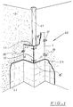
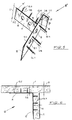
- a pipe box 40 is shown. It essentially consists of two plates 1, which are connected to one another at their right-facing longitudinal sides 1.1, 1.2 at a right angle.
- the plates 1 and 2 consist of a rigid plastic foam and are on their flat sides 1 'and 1' 'with a reinforcing fabric, e.g. a glass fiber reinforcement and a special mortar coating.
- the glass fiber reinforcement fabric on the one hand contributes to a stable connection of the two panels and on the other hand results in a good adhesive surface for a plaster or adhesive to be attached to the pipe box.
- the two plates 1 are connected to one another by angle connecting elements 10 ′′, which are spaced apart along the length.
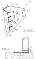
- the angle connecting element 10 ′′ is shown in detail in FIG. 5. It consists of a fastening leg 11 and a fastening leg 12 which are connected to one another at an angle ⁇ of approximately 90 °.
- the fastening leg 12 is extended by an angle leg 15 by a fastening leg 16.
- On the mounting leg 16, a locking leg 17 is articulated at an angle ⁇ . It is essential that the length of the fastening leg 16 and the length of the locking leg 17 have a length 116 and 117, which is approximately the plate thickness D correspond to plate 1. This ensures that the plates 1 are always held equally spaced together at right angles. This prevents it from sticking out or being stuck together.
- the fastening legs 11 and 12 have a longitudinal length L of 5 to 500 mm, preferably 40 mm. They have leg sides 11.1, 11.2 or 12.1 and 12.2 and are provided with cutouts 18 and 19. On the leg side 11.1, nail-shaped elevations 13.1,... 13.n are fastened approximately in the middle and on the leg side 12.1 likewise nail-shaped elevations 14.1,... 14.n, approximately in the middle. They have a length 113 or 114 of approximately 0.3 ... 0.9 ⁇ the plate thickness D of the plate 1. This ensures that when the plate 1 is inserted into the flat side 1 ′′, the nail-shaped elevations protrude 13.1, ... 13.n or 14.1, ... 14.n is prevented.
- the thickness of the nail-shaped elevations 13.1, ... 13.n or 14.1, ... 14.n is approximately 0.5-100 mm, preferably 4 mm.
- Their cross section is square, round or the like.
- angle connection elements 20 are arranged in them on the flat side 1 ′′.
- the angle connection element 20 has a plug leg 21 and a connection leg 22 which are arranged at an angle ⁇ of approximately 90 ° to one another. Both legs 21 and 22 can be joined together either by bending, welding or the like.
- the plug leg 21 has plug leg sides 21.1 and 21.2.
- pin elements 23.1,... 23n are evenly spaced approximately in the middle. It is also advantageous here if the pin elements 23.1, ... 23.n have a length 123 of 0.3, ... 0.9 ⁇ plate thickness D of plate 1. Their cross-section corresponds to that of the nail-shaped elevations 13.1, ...
- the plug leg 21 has a width B which is ⁇ the plate thickness D.
- the connecting leg 22 changes into a truncated pyramid shape. It has openings 24.1, ... 24.n. As FIG. 7 shows, these are round and oval.
- the round openings 24.1 ... which are made at the end of the connecting leg are suitable for nailing.
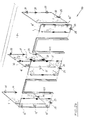
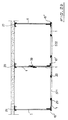
- FIGS. 2a and 2b The structure of a partition system 50 is shown in FIGS. 2a and 2b. It consists of individual panels 1 and door frame elements 51.1 and 51.2. With the help of about three of the angle connection elements 20 already described, the leftmost panel is attached to the wall. So that the panel 1 cannot tilt, the angle connection elements 20 can be guided to both sides. With the help of nails, the wall can be easily attached. In order to be able to hold the outermost left-hand wall from panel 1, the angle connection element 20 is installed on the lower narrow side.
- the connecting leg 22 is shortened to the width of the plate thickness D of the plate 1.
- a foot element 25 is fastened either by welding or screwing.
- the foot element 25 itself is adjustable in height.
- angle connection elements 10 are used. These are angled connection elements which consist of fastening legs 11 and 12 at right angles to one another with nail-shaped elevations 13.1, ... and 14.1.
- angle connection elements 10 In order to be able to hold the plate 1 securely on the other at a right angle, it is advantageous if the angle connecting elements 10 are inserted from both sides will.
- angle connection elements 10 ' as shown in the drawing, can also be used.
- This is an angular connection element which consists of two fastening legs 11 and 12 arranged at a right angle, the fastening leg 13 being extended by the fastening leg 16.
- nail-shaped elevations 13.1, ... 13.n and 14.1, ... 14.n are also attached here.
- the second door frame element 57.1 is in turn fastened in the manner already described, likewise the plate 1 on the right side in the manner already described.
- the outer plates 1 are joined together to form an angle connection in the manner described at the outset, as is the fastening of the outer plate 1 with the aid of the angle connection elements 20.
- the angle connection element 20 is also attached to the underside of individual plates 1 with one foot , the whole system can be adjusted and fastened accordingly.
- the mortar used in the tiling penetrates into the openings 24.1,... 24n as already described and ensures further attachment and fastening of the angle connection elements 20.
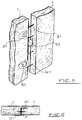
- a length connecting element 30 is used to extend and to assemble partial plates into a larger plate.
- the length connecting element 30 consists of a connecting leg 31 with connecting leg sides 31.1 and 31.2.
- the length of the pin elevations 32.1, ... 32n can be adapted to the respective requirements.
- their length and cross section correspond to the nail-shaped elevations described above.
- Pointed lance legs 33.1, 33.2 and 33.3 are arranged on the outside of the connecting leg 31 pointing in different directions.
- the lance legs 33.1, 33.2, and 33.3 have predetermined breaking lines 32.
- the length connecting element has a longitudinal length L of approximately 5 to 500 mm, preferably 100 mm.
- the length-connecting element is inserted into the opposite narrow sides of the plate 1, as shown in FIGS. 9 and 10. If the plate is approximately as wide as the distance between the lance legs 33.1 and 33.2 as shown in FIG. 10, both plates are locked.
- Such a connection is always chosen when relatively thin plates are to be connected to one another. This prevents the individual plates from bulging out and thus prevents the pin lifting elements 32.1,... From being pulled out of the plates. It is of course also possible to break off the three lance legs shown via predetermined breaking lines 32, so that a very smooth connecting leg remains.
- the partition system 50 is constructed with a total of two elements, namely the angle connecting element 10, 10 ′ or 10 ′′ and the angle connection element 20 and, in a modified form, is concealed with a foot element 25, attached and adjusted.
- a washstand 60 is built up from plates 1 made of rigid plastic foam with glass fiber reinforcement on both sides and a special mortar coating.
- a washbasin base 61 is produced from the plates 1 from two foot parts 62 and a washstand plate 63.
- the foot parts 62 have recesses 66 at their upper ends.
- a wash basin opening 63 is sawn into the vanity top 63.
- the vanity top 63 is plugged together with an end plate 64.
- this constellation can be attached to a wall 2 with the help of the angle connection elements 20 already described.
- the washstand plate 63 is plugged together with the foot parts 62 with the aid of further angle connecting elements 10 ′′.
- the foot parts 62 are arranged on the wall 2 with the aid of further angle connection elements 20.
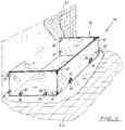
- a further embodiment is constructed with the aid of a system for holding and fastening.
- the trim apron 72 consists of several panels 1, in which the core consists of a waterproof, reinforced plastic hard foam on both sides.
- the core consists of a waterproof, reinforced plastic hard foam on both sides.
- exorded polystyrene foam sheets have been found to be suitable, on which a glass filament fabric is placed on both sides as reinforcement using a special mortar.
- Other foam materials are also suitable, for example compressed polyurethane foam.
- the individual panels 1 are joined together with the aid of the angle connection elements 10 ′′ already described in detail to form a bathtub cladding.
- the angle connecting elements 10 ′′ as shown in FIG. 4, are preferably pressed in at the upper and lower ends of two colliding plates 1.
- angle connecting elements 20 with shortened connecting legs 22 are printed as metal struts.
- the connecting leg 22 is shortened to the extent that it is no longer than the plate thickness D of the plate 1.
- the already described foot element 25, which is adjustable in height, is attached to these angle connection elements 20.
- the respective height-adjustable feet 25 stand directly on the floor 5 or on the sub-concrete of the floor. With the help of the height-adjustable feet, the tub cladding 70 can be adjusted directly under the bathtub so that there is an even and sealing connection. Then the panels 1 are fastened to the wall using the angle connection elements 20 already described.
- the bathtub cladding 70 and the wall 2 can be covered with tiles 3.1,... 3.n.
- the adhesive used when laying the tiles 3.1, ... 3n, e.g. Tile mortar also ensures that the connection legs 22 are held more firmly on the wall by the openings 24.1, ... 24.n.
- the floor 5 can then be laid out with appropriate floor tiles.
- the use of the mounting and fastening system reduces the conventional manufacture of the bath tub covering 70, including its fastening and adjustability, by approximately 30%.
- the individual nail-shaped elevations 13.1 ..., pin elements 23.1, ... and the openings 24.1 ... ensure that the individual panels are held together firmly and are held against a wall 2.
- pluggable and attachable plates 1 with the aid of the mounting and fastening system are not limited to the aforementioned exemplary embodiments. Rather, all components made of organic and / or inorganic substances, such as foam, specially kept glass fiber mats and the like, e.g. for heat insulation of large pipes can be plugged together and fastened using the system for mounting and fastening.
- the respective component is not only limited to a plate-shaped configuration.
Landscapes
- Engineering & Computer Science (AREA)
- Architecture (AREA)
- Civil Engineering (AREA)
- Structural Engineering (AREA)
- General Engineering & Computer Science (AREA)
- Public Health (AREA)
- Health & Medical Sciences (AREA)
- Physics & Mathematics (AREA)
- Electromagnetism (AREA)
- General Health & Medical Sciences (AREA)
- Epidemiology (AREA)
- Mechanical Engineering (AREA)
- Finishing Walls (AREA)
- Transplanting Machines (AREA)
- Paper (AREA)
- Joining Of Building Structures In Genera (AREA)
- Clamps And Clips (AREA)
Priority Applications (4)
| Application Number | Priority Date | Filing Date | Title |
|---|---|---|---|
| DE59409826T DE59409826D1 (de) | 1994-10-14 | 1994-10-14 | System zur Halterung und Befestigung |
| DK94116203T DK0707119T3 (da) | 1994-10-14 | 1994-10-14 | System til opstilling og fastgøring |
| EP94116203A EP0707119B1 (fr) | 1994-10-14 | 1994-10-14 | Système de montage et de fixation |
| AT94116203T ATE204046T1 (de) | 1994-10-14 | 1994-10-14 | System zur halterung und befestigung |
Applications Claiming Priority (1)
| Application Number | Priority Date | Filing Date | Title |
|---|---|---|---|
| EP94116203A EP0707119B1 (fr) | 1994-10-14 | 1994-10-14 | Système de montage et de fixation |
Publications (2)
| Publication Number | Publication Date |
|---|---|
| EP0707119A1 true EP0707119A1 (fr) | 1996-04-17 |
| EP0707119B1 EP0707119B1 (fr) | 2001-08-08 |
Family
ID=8216382
Family Applications (1)
| Application Number | Title | Priority Date | Filing Date |
|---|---|---|---|
| EP94116203A Expired - Lifetime EP0707119B1 (fr) | 1994-10-14 | 1994-10-14 | Système de montage et de fixation |
Country Status (4)
| Country | Link |
|---|---|
| EP (1) | EP0707119B1 (fr) |
| AT (1) | ATE204046T1 (fr) |
| DE (1) | DE59409826D1 (fr) |
| DK (1) | DK0707119T3 (fr) |
Cited By (1)
| Publication number | Priority date | Publication date | Assignee | Title |
|---|---|---|---|---|
| EP1201840A3 (fr) * | 2000-10-26 | 2003-09-17 | Andreas Oswald GmbH | Système à parois de séparation sur pieds |
Citations (5)
| Publication number | Priority date | Publication date | Assignee | Title |
|---|---|---|---|---|
| US2816436A (en) * | 1954-03-19 | 1957-12-17 | United States Gypsum Co | Furred wall construction |
| GB1218076A (en) * | 1968-02-20 | 1971-01-06 | Carr Fastener Co Ltd | Backing strip for attachment to an article made of foamed plastics |
| DE8600938U1 (de) * | 1986-01-16 | 1986-02-27 | Wedi, Stephan, 4407 Emsdetten | Rohrverkleidung aus Leichtbauplatten für in Raumecken verlaufende Rohrleitungen |
| EP0212315A2 (fr) * | 1985-08-05 | 1987-03-04 | LUCIFERO S.r.l. | Méthode et dispositif pour fixer des éléments de support, de liaison ou d'articulation sur des panneaux ou blocs de polystyrène expansé ou similaire |
| EP0596512A1 (fr) * | 1992-11-06 | 1994-05-11 | Helmut Wedi | Système de panneaux à montage rapide |
-
1994
- 1994-10-14 DE DE59409826T patent/DE59409826D1/de not_active Expired - Lifetime
- 1994-10-14 DK DK94116203T patent/DK0707119T3/da active
- 1994-10-14 AT AT94116203T patent/ATE204046T1/de not_active IP Right Cessation
- 1994-10-14 EP EP94116203A patent/EP0707119B1/fr not_active Expired - Lifetime
Patent Citations (5)
| Publication number | Priority date | Publication date | Assignee | Title |
|---|---|---|---|---|
| US2816436A (en) * | 1954-03-19 | 1957-12-17 | United States Gypsum Co | Furred wall construction |
| GB1218076A (en) * | 1968-02-20 | 1971-01-06 | Carr Fastener Co Ltd | Backing strip for attachment to an article made of foamed plastics |
| EP0212315A2 (fr) * | 1985-08-05 | 1987-03-04 | LUCIFERO S.r.l. | Méthode et dispositif pour fixer des éléments de support, de liaison ou d'articulation sur des panneaux ou blocs de polystyrène expansé ou similaire |
| DE8600938U1 (de) * | 1986-01-16 | 1986-02-27 | Wedi, Stephan, 4407 Emsdetten | Rohrverkleidung aus Leichtbauplatten für in Raumecken verlaufende Rohrleitungen |
| EP0596512A1 (fr) * | 1992-11-06 | 1994-05-11 | Helmut Wedi | Système de panneaux à montage rapide |
Cited By (1)
| Publication number | Priority date | Publication date | Assignee | Title |
|---|---|---|---|---|
| EP1201840A3 (fr) * | 2000-10-26 | 2003-09-17 | Andreas Oswald GmbH | Système à parois de séparation sur pieds |
Also Published As
| Publication number | Publication date |
|---|---|
| EP0707119B1 (fr) | 2001-08-08 |
| ATE204046T1 (de) | 2001-08-15 |
| DK0707119T3 (da) | 2001-11-26 |
| DE59409826D1 (de) | 2001-09-13 |
Similar Documents
| Publication | Publication Date | Title |
|---|---|---|
| AT395453B (de) | Wandelementanordnung | |
| EP2354368B1 (fr) | Etrier de fixation pour isolations murales | |
| EP0153660A2 (fr) | Elément de coffrage pour la construction à coffrage permanent | |
| WO1996036777A1 (fr) | Element de paroi finie a conduits integres | |
| EP2181227B1 (fr) | Element de paroi composite transportable prefabrique compose de parpaings de coffrage | |
| DE102020120983B4 (de) | Raumteil-Modul, insbesondere Gewerbe-Modul daraus hergestelltes Gebäude, sowie jeweils ein Herstellverfahren hierfür | |
| EP0639677B1 (fr) | Bâtiment composé par des modules de cellules préfabriquées | |
| DE102007032397B4 (de) | Verfahren zur Herstellung eines transportablen vorgefertigten Gebäudewandelements aus Schalungssteinen | |
| DE3722849C2 (fr) | ||
| EP0707119B1 (fr) | Système de montage et de fixation | |
| DE19640633A1 (de) | Verfahren zur Befestigung von Strukturelementen, entsprechendes Strukturelement und Halteelement hierfür | |
| DE102015015604B4 (de) | Aufnahmeelement für eine Beschattungseinrichtung und Verfahren zum Befestigen eines solchen an der Außenseite eines Gebäudes | |
| EP0070962B1 (fr) | Bâtiment à assembler à partir de pièces préfabriquées | |
| EP0227937A1 (fr) | Balcon à rajouter sur un immeuble existant | |
| DE9303937U1 (de) | Sanitaerkabine | |
| DE9416557U1 (de) | System zur Halterung und Befestigung | |
| DE29509938U1 (de) | Schalstütze | |
| AT5562U1 (de) | Fertighaussystem | |
| DE102019119417A1 (de) | Schalungselement | |
| DE10061477B4 (de) | Vorgefertigtes, großformatiges plattenförmiges Bauelement | |
| EP0154913A2 (fr) | Profilé permettant la fixation à des parois | |
| DE3426831A1 (de) | Aus vorgefertigten wand- und deckentafeln bestehendes raumbausystem fuer schiffe und aehnliche baukoerper | |
| DE2131009A1 (de) | Bauelement,insbesondere aus Kunststoff | |
| DE2648935A1 (de) | Aus wenigstens einer bauplatte bestehende montagewand | |
| DE29805952U1 (de) | Schalldämmende Innen- oder Außenwandbekleidung |
Legal Events
| Date | Code | Title | Description |
|---|---|---|---|
| PUAI | Public reference made under article 153(3) epc to a published international application that has entered the european phase |
Free format text: ORIGINAL CODE: 0009012 |
|
| AK | Designated contracting states |
Kind code of ref document: A1 Designated state(s): AT BE CH DE DK ES FR GB GR IE IT LI NL PT SE |
|
| 17P | Request for examination filed |
Effective date: 19960706 |
|
| 17Q | First examination report despatched |
Effective date: 19990415 |
|
| RAP1 | Party data changed (applicant data changed or rights of an application transferred) |
Owner name: WEDI, STEPHAN |
|
| RIN1 | Information on inventor provided before grant (corrected) |
Inventor name: WEDI, STEPHAN |
|
| GRAG | Despatch of communication of intention to grant |
Free format text: ORIGINAL CODE: EPIDOS AGRA |
|
| GRAG | Despatch of communication of intention to grant |
Free format text: ORIGINAL CODE: EPIDOS AGRA |
|
| GRAH | Despatch of communication of intention to grant a patent |
Free format text: ORIGINAL CODE: EPIDOS IGRA |
|
| GRAH | Despatch of communication of intention to grant a patent |
Free format text: ORIGINAL CODE: EPIDOS IGRA |
|
| GRAA | (expected) grant |
Free format text: ORIGINAL CODE: 0009210 |
|
| AK | Designated contracting states |
Kind code of ref document: B1 Designated state(s): AT BE CH DE DK ES FR GB GR IE IT LI NL PT SE |
|
| PG25 | Lapsed in a contracting state [announced via postgrant information from national office to epo] |
Ref country code: IT Free format text: LAPSE BECAUSE OF FAILURE TO SUBMIT A TRANSLATION OF THE DESCRIPTION OR TO PAY THE FEE WITHIN THE PRESCRIBED TIME-LIMIT;WARNING: LAPSES OF ITALIAN PATENTS WITH EFFECTIVE DATE BEFORE 2007 MAY HAVE OCCURRED AT ANY TIME BEFORE 2007. THE CORRECT EFFECTIVE DATE MAY BE DIFFERENT FROM THE ONE RECORDED. Effective date: 20010808 Ref country code: IE Free format text: LAPSE BECAUSE OF FAILURE TO SUBMIT A TRANSLATION OF THE DESCRIPTION OR TO PAY THE FEE WITHIN THE PRESCRIBED TIME-LIMIT Effective date: 20010808 Ref country code: GR Free format text: LAPSE BECAUSE OF NON-PAYMENT OF DUE FEES Effective date: 20010808 |
|
| REF | Corresponds to: |
Ref document number: 204046 Country of ref document: AT Date of ref document: 20010815 Kind code of ref document: T |
|
| REG | Reference to a national code |
Ref country code: CH Ref legal event code: EP |
|
| GBT | Gb: translation of ep patent filed (gb section 77(6)(a)/1977) |
Effective date: 20010808 |
|
| REG | Reference to a national code |
Ref country code: IE Ref legal event code: FG4D Free format text: GERMAN |
|
| REF | Corresponds to: |
Ref document number: 59409826 Country of ref document: DE Date of ref document: 20010913 |
|
| REG | Reference to a national code |
Ref country code: CH Ref legal event code: NV Representative=s name: PATMED AG |
|
| PG25 | Lapsed in a contracting state [announced via postgrant information from national office to epo] |
Ref country code: SE Free format text: LAPSE BECAUSE OF FAILURE TO SUBMIT A TRANSLATION OF THE DESCRIPTION OR TO PAY THE FEE WITHIN THE PRESCRIBED TIME-LIMIT Effective date: 20011108 Ref country code: PT Free format text: LAPSE BECAUSE OF FAILURE TO SUBMIT A TRANSLATION OF THE DESCRIPTION OR TO PAY THE FEE WITHIN THE PRESCRIBED TIME-LIMIT Effective date: 20011108 |
|
| REG | Reference to a national code |
Ref country code: DK Ref legal event code: T3 |
|
| REG | Reference to a national code |
Ref country code: GB Ref legal event code: IF02 |
|
| ET | Fr: translation filed | ||
| PG25 | Lapsed in a contracting state [announced via postgrant information from national office to epo] |
Ref country code: ES Free format text: LAPSE BECAUSE OF FAILURE TO SUBMIT A TRANSLATION OF THE DESCRIPTION OR TO PAY THE FEE WITHIN THE PRESCRIBED TIME-LIMIT Effective date: 20020228 |
|
| PLBE | No opposition filed within time limit |
Free format text: ORIGINAL CODE: 0009261 |
|
| STAA | Information on the status of an ep patent application or granted ep patent |
Free format text: STATUS: NO OPPOSITION FILED WITHIN TIME LIMIT |
|
| 26N | No opposition filed | ||
| PGFP | Annual fee paid to national office [announced via postgrant information from national office to epo] |
Ref country code: DK Payment date: 20021002 Year of fee payment: 9 |
|
| PG25 | Lapsed in a contracting state [announced via postgrant information from national office to epo] |
Ref country code: DK Free format text: LAPSE BECAUSE OF NON-PAYMENT OF DUE FEES Effective date: 20040430 |
|
| REG | Reference to a national code |
Ref country code: DK Ref legal event code: EBP |
|
| PGFP | Annual fee paid to national office [announced via postgrant information from national office to epo] |
Ref country code: DE Payment date: 20091026 Year of fee payment: 16 Ref country code: CH Payment date: 20091026 Year of fee payment: 16 Ref country code: AT Payment date: 20091015 Year of fee payment: 16 |
|
| PGFP | Annual fee paid to national office [announced via postgrant information from national office to epo] |
Ref country code: NL Payment date: 20091016 Year of fee payment: 16 |
|
| PGFP | Annual fee paid to national office [announced via postgrant information from national office to epo] |
Ref country code: GB Payment date: 20091022 Year of fee payment: 16 Ref country code: FR Payment date: 20091110 Year of fee payment: 16 |
|
| PGFP | Annual fee paid to national office [announced via postgrant information from national office to epo] |
Ref country code: BE Payment date: 20091130 Year of fee payment: 16 |
|
| BERE | Be: lapsed |
Owner name: *WEDI STEPHAN Effective date: 20101031 |
|
| REG | Reference to a national code |
Ref country code: NL Ref legal event code: V1 Effective date: 20110501 |
|
| REG | Reference to a national code |
Ref country code: CH Ref legal event code: PL |
|
| GBPC | Gb: european patent ceased through non-payment of renewal fee |
Effective date: 20101014 |
|
| PG25 | Lapsed in a contracting state [announced via postgrant information from national office to epo] |
Ref country code: LI Free format text: LAPSE BECAUSE OF NON-PAYMENT OF DUE FEES Effective date: 20101031 Ref country code: CH Free format text: LAPSE BECAUSE OF NON-PAYMENT OF DUE FEES Effective date: 20101031 Ref country code: FR Free format text: LAPSE BECAUSE OF NON-PAYMENT OF DUE FEES Effective date: 20101102 |
|
| REG | Reference to a national code |
Ref country code: FR Ref legal event code: ST Effective date: 20110630 |
|
| PG25 | Lapsed in a contracting state [announced via postgrant information from national office to epo] |
Ref country code: NL Free format text: LAPSE BECAUSE OF NON-PAYMENT OF DUE FEES Effective date: 20110501 Ref country code: GB Free format text: LAPSE BECAUSE OF NON-PAYMENT OF DUE FEES Effective date: 20101014 Ref country code: BE Free format text: LAPSE BECAUSE OF NON-PAYMENT OF DUE FEES Effective date: 20101031 Ref country code: AT Free format text: LAPSE BECAUSE OF NON-PAYMENT OF DUE FEES Effective date: 20101014 |
|
| REG | Reference to a national code |
Ref country code: DE Ref legal event code: R119 Ref document number: 59409826 Country of ref document: DE Effective date: 20110502 |
|
| PG25 | Lapsed in a contracting state [announced via postgrant information from national office to epo] |
Ref country code: DE Free format text: LAPSE BECAUSE OF NON-PAYMENT OF DUE FEES Effective date: 20110502 |