EP0212366A2 - Spring-mounted gripper for sheet-fed rotary printing machines - Google Patents
Spring-mounted gripper for sheet-fed rotary printing machines Download PDFInfo
- Publication number
- EP0212366A2 EP0212366A2 EP86110488A EP86110488A EP0212366A2 EP 0212366 A2 EP0212366 A2 EP 0212366A2 EP 86110488 A EP86110488 A EP 86110488A EP 86110488 A EP86110488 A EP 86110488A EP 0212366 A2 EP0212366 A2 EP 0212366A2
- Authority
- EP
- European Patent Office
- Prior art keywords
- gripper
- clamping piece
- sheet
- finger
- movement
- Prior art date
- Legal status (The legal status is an assumption and is not a legal conclusion. Google has not performed a legal analysis and makes no representation as to the accuracy of the status listed.)
- Granted
Links
Images
Classifications
-
- B—PERFORMING OPERATIONS; TRANSPORTING
- B41—PRINTING; LINING MACHINES; TYPEWRITERS; STAMPS
- B41F—PRINTING MACHINES OR PRESSES
- B41F21/00—Devices for conveying sheets through printing apparatus or machines
- B41F21/10—Combinations of transfer drums and grippers
- B41F21/104—Gripper details
Definitions
- the invention relates to a resilient gripper for sheet-fed rotary printing machines according to the preamble of the first claim.
- resilient grippers are designed in such a way that they can evenly absorb the tension that is exerted on the grippers by the paper. Since a slight pulling out of the paper from the gripper causes doubling or registration problems, one always tries to design the gripper with the maximum holding force. This means that the gripper springs have a very steep characteristic. The bearing clearances of all grippers must also be kept very tight, since the slightest air automatically affects fitting or doubling when closing. This small bearing play inevitably leads to high friction of the grippers at the bearing point, i.e. that part of the closing spring force is consumed in the camp itself. It also follows from this that the bearings of the gripper shaft must be kept very stable in order to absorb a deformation when the grippers close impulsively. A disadvantage of this is the creation of very high mass forces.
- DD-PS 66 634 From DD-PS 66 634 it is known to support a one-piece gripper lever on a gripper shaft and to adjust its pretensioning force by means of two compression springs.
- the disadvantage is that the gripper lever determined its statically The position loses if the fullest possible compensation of the bearing force is to be achieved. With very high machine speeds and increased preload forces, adequate centering is no longer possible, for example as a result of spurious vibrations that are introduced into the machine.
- Another disadvantage is the relatively large radius of inertia and the mass of the vibrating parts for initiating the holding process.
- a gripper is known in which the axis of the gripper finger joint is pivotally mounted in a swivel joint parallel to the gripper shaft, the axis of the gripper finger joint being located approximately on the straight line extending away from the gripper tip, which is the supporting surface for the hook tip connects to the axis of the hook shaft.
- the geometry shown in FIG. 1 shows that the force exerted by the gripper tip on the gripper support continues to have a component in the direction of sheet travel. As a result, there is still a risk of the sheet moving, and there is also a possible torsion of the gripper shaft with high pretensioning forces, although an improvement over conventional grippers with a circular movement about the gripper shaft axis can be achieved.
- DD-PS 67 992 From DD-PS 67 992 it is known to mount a gripper by means of a clamping piece on a pivotable gripper shaft having a fixed axis and a gripper tongue in a first movement phase a circular movement around the gripper shaft axis and in a second movement phase an approximately perpendicular with respect to the gripper support To give movement.
- This gripper arrangement also works a non-positively working parallel leaf spring arrangement and a gripper tongue that can not withstand large closing forces without bulging. The gripper is therefore completely unsuitable for the highest possible closing forces.
- a vertically closing gripper with a controlled gripper shaft is known from DE-PS 2 030 040.
- a disadvantage is the frictional control of the gripper shaft relative to the fulcrum of a control lever by means of a guide on a control cam.
- the additional control effort leads to an increase in the inertial forces of the system vibrating with a large radius of inertia and thus to a reduction in the performance of the printing press.
- the control cam is heavily soiled, it is no longer possible to guide the second vertical movement phase exactly.
- the invention has for its object a resilient gripper of the type mentioned with regard to the mass and the carrier optimize the radii of the components and to give the gripper finger a movement perpendicular to the gripper support or a slight pulling movement in a second movement phase.
- the advantages of the solution according to the invention are that irrespective of a soft gripper support without bulging the gripper tip in an extended speed range with high pretensioning forces and overpressures in the direction of sheet travel, neither disturbing forces nor vibrations can have an effect.
- the holding effect is improved by an increased forced running of a vertical closing process or a closing process that takes place with little pulling movement.
- the gripper finger maintains its statically determined position and does not react so slowly. There are also minimal gripper masses and minimal acceleration forces.
- the gripper finger 2 cooperating with the gripper support 1 can be formed in one piece as a sheet metal part by means of links 11, 12 preloaded via stop screw 8 and stop 13, which are elastically deformable.
- the handlebars 11, 12 are with a clamp piece firmly connected, which consists of preformed intertwined sheet metal strips 14, 15 which can be clamped on the gripper shaft 7 by means of a screw.
- the links 11, 12 must also control a vertical movement or slight pulling movement of the gripper finger 2 in a second movement phase, which is similar to the movement that is generated by resilient guide elements in the form of leaf springs.
- corresponding connecting lines of the links 11, 12 are provided, which likewise run through the fixed axis of the gripper shaft 7.
Landscapes
- Supply, Installation And Extraction Of Printed Sheets Or Plates (AREA)
- Feeding Of Articles By Means Other Than Belts Or Rollers (AREA)
- Discharge By Other Means (AREA)
Abstract
Die Erfindung betrifft einen federnden Greifer für Bogenrotationsdruckmaschinen, der aus einem eine Schwenkbewegung ausführenden Klemmstück besteht und einen zum Klemmstück federnd angeordneten Greiferfinger aufweist, dessen Vorspannkraft einstellbar ist. Aufgabe der Erfindung ist es, den federnden Greifer hinsichtlich der Masse und der Trägheitsradien der Bauteile zu optimieren und den Greiferfinger in einer zweiten Bewegungsphase eine Bewegung senkrecht zur Greiferauflage oder eine geringe Zugbewegung zu erteilen. Erfindungsgemäß ist hierzu der Greiferfinger (2) mit dem Klemmstück (3) über vorgespannte Blattfedern (4, 5) verbunden und die Anlenkpunkte jeder Blattfeder (4 bzw. 5) liegen auf einer Verbindungslinie, die durch die ortsfeste Achse der Greiferwelle (7) vertäuft.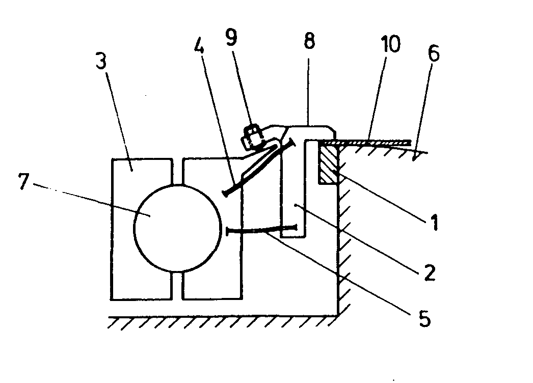
Description
Die Erfindung betrifft einen federnden Greifer für Bogenrotationsdruckmaschinen nach dem Oberbegriff des ersten Patentanspruchs.The invention relates to a resilient gripper for sheet-fed rotary printing machines according to the preamble of the first claim.
Bekanntlich sind federnde Greifer so gestaltet, daß sie den Zug, der vom Papier auf die Greifer ausgeübt wird, über Kraftschluß gleichmäßig aufnehmen können. Da ein geringfügiges Herausziehen des Papiers aus dem Greifer Doublier- bzw. Passerprobleme hervorruft, ist man immer bestrebt, den Greifer mit der maximalen Haltekraft auszulegen. Dies führt dazu, daß die Greiferfedern eine sehr steile Kennlinie haben. Die Lagerspiele aller Greifer müssen ebenfalls sehr eng gehalten werden, da sich die geringste Luft beim Schließen automatisch auf das Passen bzw. Doublieren auswirkt. Mit diesem geringen Lagerspiel ist zwangsläufig eine hohe Reibung der Greifer an der Lagerstelle verbunden, d.h. daß ein Teil der Schließfederkraft im Lager selbst aufgezehrt wird. Ferner ergibt sich hieraus, daß die Lager der Greiferwelle sehr stabil gehalten werden müssen, um eine Verformung beim impulsartigen Schließen der Greifer aufzufangen. Ein Nachteil hieraus ist das Entstehen sehr hoher Massenkräfte.As is known, resilient grippers are designed in such a way that they can evenly absorb the tension that is exerted on the grippers by the paper. Since a slight pulling out of the paper from the gripper causes doubling or registration problems, one always tries to design the gripper with the maximum holding force. This means that the gripper springs have a very steep characteristic. The bearing clearances of all grippers must also be kept very tight, since the slightest air automatically affects fitting or doubling when closing. This small bearing play inevitably leads to high friction of the grippers at the bearing point, i.e. that part of the closing spring force is consumed in the camp itself. It also follows from this that the bearings of the gripper shaft must be kept very stable in order to absorb a deformation when the grippers close impulsively. A disadvantage of this is the creation of very high mass forces.
Insgesamt kann man sagen, daß bekannte Greifersysteme zum Steuern sehr hohe Kräfte benötigen, die nur z.T. zur Haltekraft des Bogens genutzt werden können und/oder das durch diese hohen Kräfte, schlagartig auftretend, Störschwingungen in die Maschine eingebracht werden.All in all, it can be said that known gripper systems require very high forces to control, which in some cases only. can be used to hold the bow and / or by these high forces, suddenly occurring, disturbing vibrations are introduced into the machine.
Aus der DD-PS 66 634 ist es bekannt, einen einteiligen Greiferhebel auf einer Greiferwelle abzustützen und dessen Vorspannkraft durch zwei Druckfedern einzustellen. Von Nachteil ist, daß der Greiferhebel seine statisch bestimmte Lage verliert, wenn eine möglichst vollständige Kompensation der Lagerkraft erreicht werden soll. Bei sehr hohen Maschinengeschwindigkeiten und erhöhten Vorspannkräften ist keine ausreichende Zentrierung, z.B. infolge Störschwingungen, die in die Maschine eingebracht werden, mehr möglich. Von Nachteil sind ferner der verhältnismäßig große Trägheitsradius und die Masse der schwingenden Teile für das Einleiten des Haltevorganges.From DD-PS 66 634 it is known to support a one-piece gripper lever on a gripper shaft and to adjust its pretensioning force by means of two compression springs. The disadvantage is that the gripper lever determined its statically The position loses if the fullest possible compensation of the bearing force is to be achieved. With very high machine speeds and increased preload forces, adequate centering is no longer possible, for example as a result of spurious vibrations that are introduced into the machine. Another disadvantage is the relatively large radius of inertia and the mass of the vibrating parts for initiating the holding process.
Aus der DE-OS 1 908 181 ist ein Greifer bekannt, bei dem die Achse des Greiferfingergelenkes in einem zur Greiferwelle parallelen Drehgelenk schwenkbar gelagert ist, wobei die Achse des Greiferfingergelenks annähernd auf der von der Greiferspitze wegweisenden Verlängerung einer Geraden gelegen ist, welche die Abstützfläche für die Greiferspitze mit der Achse der Greiferwelle verbindet. Aus der in Fig. 1 gezeigten Geometrie geht hervor, daß die von der Greiferspitze auf die Greiferauflage ausgeübte Kraft weiterhin eine Komponente in Bogenlaufrichtung aufweist. Die Gefahr des Verschiebens des Bogens besteht dadurch, sowie durch eine möglich Torsion der Greiferwelle bei hohen Vorspannkräften auch weiterhin, wenn auch eine Verbesserung gegenüber üblichen Greifern mit kreisförmiger Bewegung um die Greiferwellenachse erreichbar ist.From DE-OS 1 908 181 a gripper is known in which the axis of the gripper finger joint is pivotally mounted in a swivel joint parallel to the gripper shaft, the axis of the gripper finger joint being located approximately on the straight line extending away from the gripper tip, which is the supporting surface for the hook tip connects to the axis of the hook shaft. The geometry shown in FIG. 1 shows that the force exerted by the gripper tip on the gripper support continues to have a component in the direction of sheet travel. As a result, there is still a risk of the sheet moving, and there is also a possible torsion of the gripper shaft with high pretensioning forces, although an improvement over conventional grippers with a circular movement about the gripper shaft axis can be achieved.
Aus der DD-PS 67 992 ist es bekannt, einen Greifer mittels Klemmstück an einer eine ortsfeste Achse aufweisenden schwenkbaren Greiferwelle zu lagern und einer Greiferzunge in einer ersten Bewegungsphase eine Kreisbewegung um die Greiferwellenachse und in einer zweiten Bewegungsphase eine in Bezug auf die Greiferauflage annähernd senkrechte Bewegung zu erteilen. Diese Greiferanordnung wirkt aber mit einer kraftschlüssig arbeitenden parallelen Blattfederanordnung und einer Greiferzunge zusammen, die keine großen Schließkräfte erträgt, ohne zu beulen. Der Greifer ist demnach für möglichst hohe Schließkräfte völlig ungeeignet.From DD-PS 67 992 it is known to mount a gripper by means of a clamping piece on a pivotable gripper shaft having a fixed axis and a gripper tongue in a first movement phase a circular movement around the gripper shaft axis and in a second movement phase an approximately perpendicular with respect to the gripper support To give movement. This gripper arrangement also works a non-positively working parallel leaf spring arrangement and a gripper tongue that can not withstand large closing forces without bulging. The gripper is therefore completely unsuitable for the highest possible closing forces.
Ein senkrecht schließender Greifer mit einer gesteuerten Greiferwelle ist aus der DE-PS 2 030 040 bekannt. Von Nachteil ist die kraftschlüssige Steuerung der Greiferwelle relativ zum Drehpunkt eines Steuerhebels mittels einer Führung auf einer Steuerkurve. Der zusätzliche Steuerungsaufwand führt zu einer Erhöhung der Massenkräfte des mit großem Trägheitsradius schwingenden Systems und damit zu einer Verminderung des Leistungsvermögens der Druckmaschine. Außerdem ist bei größeren Verschmutzungen der Steuerkurve keine exakte Führung der zweiten senkrechten Bewegungsphase mehr möglich.A vertically closing gripper with a controlled gripper shaft is known from DE-PS 2 030 040. A disadvantage is the frictional control of the gripper shaft relative to the fulcrum of a control lever by means of a guide on a control cam. The additional control effort leads to an increase in the inertial forces of the system vibrating with a large radius of inertia and thus to a reduction in the performance of the printing press. In addition, if the control cam is heavily soiled, it is no longer possible to guide the second vertical movement phase exactly.
Ferner ist es aus der DE-OS 3 130 689 bekannt, in Verbindung mit einer weichen Greiferauflage einen eine flache Greiferflugbahn ausführenden und in der letzten Bewegungsphase senkrecht schließenden Greiferfinger mit einer in dem Greiferfinger angeordneten und gegen den Bogengreiferaufschlag wirkenden federnden Anschlagschraube zu versehen. Eine weitere Stellschraube ist erforderlich, um federnd miteinander gekoppelte Halter einzustellen, mittels denen der Greiferfinger der Greiferwelle zugeordnet ist. Von Nachteil ist, daß der Greiferfinger einer weichen Greiferauflage zugeordnet werden muß und an zwei Stellschrauben umständliche Einstellungen erforderlich sind, um eine lagegenaue Obergabe zu erreichen. Bei höheren Maschinengeschwindigkeiten wird der Schließvorgang unsauber eingeleitet.Furthermore, it is known from DE-OS 3 130 689 to provide, in conjunction with a soft gripper pad, a gripper finger that executes a flat gripper trajectory and closes vertically in the last phase of movement with a resilient stop screw arranged in the gripper finger and acting against the bow gripper impact. A further set screw is required in order to adjust the spring-coupled holder by means of which the gripper finger is assigned to the gripper shaft. The disadvantage is that the gripper finger must be assigned to a soft gripper pad and cumbersome adjustments are required on two adjusting screws in order to achieve an accurate transfer. The closing process is initiated improperly at higher machine speeds.
Der Erfindung liegt die Aufgabe zugrunde, einen federnden Greifer genannter Art hinsichtlich der Masse und der Trägheitsradien der Bauteile zu optimieren und dem Greiferfinger in einer zweiten Bewegungsphase eine Bewegung senkrecht zur Greiferauflage oder eine geringe Zugbewegung zu erteilen.The invention has for its object a resilient gripper of the type mentioned with regard to the mass and the carrier optimize the radii of the components and to give the gripper finger a movement perpendicular to the gripper support or a slight pulling movement in a second movement phase.
Die Aufgabe wird durch die kennzeichnenden Merkmale des ersten Patentanspruchs gelöst. Weiterbildungen der Erfindung ergeben sich aus dem Unteranspruch, der Zeichnung und der Beschreibung.The object is achieved by the characterizing features of the first claim. Further developments of the invention result from the subclaim, the drawing and the description.
Die Vorteile der erfindungsgemäßen Lösung bestehen darin, daß unabhängig von einer weichen Greiferauflage ohne Ausbeulen der Greiferspitze in einem erweiterten Geschwindigkeitsbereich bei hohen Vorspannkräften und Überdrückungen in Bogenlaufrichtung sich weder störende Kräfte noch Schwingungen auswirken können. Der Halteeffekt wird durch einen erhöhten Zwangslauf eines senkrechten oder mit geringer Zugbewegung erfolgenden Schließvorganges verbessert. Der Greiferfinger behält seine statisch bestimmte Lage und reagiert nicht so träge. Es ergeben sich ferner minimale Greifermassen und minimale Beschleunigungskräfte.The advantages of the solution according to the invention are that irrespective of a soft gripper support without bulging the gripper tip in an extended speed range with high pretensioning forces and overpressures in the direction of sheet travel, neither disturbing forces nor vibrations can have an effect. The holding effect is improved by an increased forced running of a vertical closing process or a closing process that takes place with little pulling movement. The gripper finger maintains its statically determined position and does not react so slowly. There are also minimal gripper masses and minimal acceleration forces.
Ein Ausführungsbeispiel der Erfindung wird nachfolgend anhand einer Zeichnung näher beschrieben.An embodiment of the invention is described below with reference to a drawing.
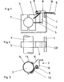
Hierzu zeigt:
- Fig. 1 eine Seitenansicht eines Greifers,
- Fig. 2 eine Draufsicht auf Fig. 1,
- Fig. 3 eine Seitenansicht eines weiteren Greifers.
- 1 is a side view of a gripper,
- 2 is a plan view of FIG. 1,
- Fig. 3 is a side view of another gripper.
Gemäß einer anderen in der Zeichnung in Fig. 3 dargestellten Ausführung der Erfindung kann der mit der Greiferauflage 1 zusammenarbeitende Greiferfinger 2 einstückig als Blechformteil durch über Anschlagschraube 8 und Anschlag 13 vorgespannte Lenker 11, 12 gebildet sein, die elastisch verformbar sind. Die Lenker 11, 12 sind mit einem Klemmstück fest verbunden, welches aus vorgeformten ineinander gehängten Blechstreifen 14, 15 besteht, die mittels einer Schraube auf der Greiferwelle 7 klemmbar sind.According to another embodiment of the invention shown in the drawing in FIG. 3, the
Die Lenker 11, 12 müssen ebenfalls eine Senkrechtbewegung oder geringe Zugbewegung des Greiferfingers 2 in einer zweiten Bewegungsphase steuern, die ähnlich der Bewegung ist, wie sie durch federnde Führungselemente in Form von Blattfedern erzeugt wird. Hierzu sind entsprechende Verbindungslinien der Lenker 11, 12 vorgesehen, welche ebenfalls durch die ortsfeste Achse der Greiferwelle 7 verlaufen.The
- 1 Greiferauflage1 gripper pad
- 2 Greiferfinger2 gripper fingers
- 3 Klemmstück3 clamping piece
- 4 Blattfeder4 leaf springs
- 5 "5 "
- 6 Zylinder6 cylinders
- 7 Greiferwelle7 gripper shaft
- 8 Greiferspitze8 gripper tip
- 9 Anschlagschraube9 stop screw
- 10 Bogen10 sheets
- 11 Lenker11 handlebars
- 12 Lenker12 handlebars
- 13 Anschlag13 stop
- 14 Blechstreifen14 metal strips
- 15 Blechstreifen15 metal strips
Claims (2)
Priority Applications (1)
| Application Number | Priority Date | Filing Date | Title |
|---|---|---|---|
| AT86110488T ATE46859T1 (en) | 1985-08-19 | 1986-07-30 | RESILIENT GRIPPER FOR SHEET ROTARY PRINTING MACHINES. |
Applications Claiming Priority (2)
| Application Number | Priority Date | Filing Date | Title |
|---|---|---|---|
| DE3529612 | 1985-08-19 | ||
| DE19853529612 DE3529612A1 (en) | 1985-08-19 | 1985-08-19 | SPRING GRIPPER FOR ARC ROTATION PRINTING MACHINES |
Publications (3)
| Publication Number | Publication Date |
|---|---|
| EP0212366A2 true EP0212366A2 (en) | 1987-03-04 |
| EP0212366A3 EP0212366A3 (en) | 1987-11-04 |
| EP0212366B1 EP0212366B1 (en) | 1989-10-04 |
Family
ID=6278821
Family Applications (1)
| Application Number | Title | Priority Date | Filing Date |
|---|---|---|---|
| EP86110488A Expired EP0212366B1 (en) | 1985-08-19 | 1986-07-30 | Spring-mounted gripper for sheet-fed rotary printing machines |
Country Status (5)
| Country | Link |
|---|---|
| US (1) | US4719854A (en) |
| EP (1) | EP0212366B1 (en) |
| JP (1) | JPS6251448A (en) |
| AT (1) | ATE46859T1 (en) |
| DE (1) | DE3529612A1 (en) |
Families Citing this family (8)
| Publication number | Priority date | Publication date | Assignee | Title |
|---|---|---|---|---|
| DE3806526A1 (en) * | 1988-03-01 | 1989-09-14 | Heidelberger Druckmasch Ag | DEVICE FOR TENSIONING FLEXIBLE PRINTING PLATES ON THE PLATE CYLINDER OF ROTARY PRINTING MACHINES |
| DE4101987A1 (en) * | 1991-01-24 | 1992-07-30 | Roland Man Druckmasch | Sheet gripper for rotary printing machine - has self-aligning claw attached by leaf spring to gripper finger |
| DE4127713C2 (en) * | 1991-08-22 | 1996-03-21 | Koenig & Bauer Albert Ag | Grippers for sheet-fed rotary printing machines |
| GB2268928B (en) * | 1992-07-22 | 1995-10-18 | Heidelberger Druckmasch Ag | Sheet gripper for a paper-carrying cylinder of a sheet-fed printing press |
| DE19816512B4 (en) | 1997-08-18 | 2008-08-28 | Heidelberger Druckmaschinen Ag | Sheet gripper in a sheet-fed rotary printing machine |
| DE102007005958B4 (en) * | 2006-02-20 | 2015-07-16 | Heidelberger Druckmaschinen Ag | Device for sheet transport |
| CN101024328B (en) * | 2006-02-20 | 2010-12-15 | 海德堡印刷机械股份公司 | Sheet-transporting apparatus |
| DE102009027508A1 (en) * | 2009-07-07 | 2011-01-20 | Manroland Ag | Grip arm for sheet-handling machine, has longitudinal strut lying against gripper segment, where relative movement between longitudinal strut and cross member takes place by force acting on longitudinal strut |
Family Cites Families (18)
| Publication number | Priority date | Publication date | Assignee | Title |
|---|---|---|---|---|
| DD66634A (en) * | ||||
| DD67992A (en) * | ||||
| DE371756C (en) * | 1923-03-21 | Schnellpressenfabrik Act Ges H | On the gripper rod rotatably arranged gripper for attaching and depositing devices as well as for printing cylinders on printing machines | |
| DE356241C (en) * | 1920-02-22 | 1922-07-18 | Maschf Augsburg Nuernberg Ag | Gripper for the printing cylinders of printing machines |
| DE670298C (en) * | 1937-02-28 | 1939-01-16 | Albert Schnellpressen | Sheet gripper for printing machines loosely arranged on a pivoting spindle |
| US2378478A (en) * | 1943-02-18 | 1945-06-19 | Goss Printing Press Co Ltd | Printing press gripper mechanism |
| SU67992A1 (en) | 1945-10-16 | 1946-11-30 | И.Н. Новиков | Device for the suspension of carts |
| US2906204A (en) * | 1957-06-24 | 1959-09-29 | Cottrell Company | Gripper assemblies |
| US2935937A (en) * | 1957-10-29 | 1960-05-10 | Davidson Corp | Plate clamp for printing machine |
| US3044771A (en) * | 1960-04-18 | 1962-07-17 | Harris Intertype Corp | Sheet handling cylinder |
| AT298522B (en) * | 1968-02-21 | 1972-04-15 | Polygraph Leipzig | DEVICE FOR CLAMPING MATERIAL SHEETS |
| US3536321A (en) * | 1968-06-13 | 1970-10-27 | Planeta Veb Druckmasch Werke | Device for clamping sheet material |
| DE1908181A1 (en) * | 1969-02-19 | 1970-11-05 | Roland Offsetmaschf | Clamp gripper for sheet-fed rotary printing machines |
| US3606308A (en) * | 1969-06-20 | 1971-09-20 | Miller Printing Machinery Co | Sheet gripping device |
| ES230780Y (en) * | 1977-08-26 | 1978-07-01 | CLAMP AND CLAMP ASSEMBLY FOR THE TRANSPORT OF SHEETS IN LITHOGRAPHIC MACHINES. | |
| DD154083A1 (en) * | 1980-11-17 | 1982-02-24 | Arndt Jentzsch | ARCH OVERALL DEVICE |
| DE3267440D1 (en) * | 1981-09-04 | 1985-12-19 | Motter Printing Press Co | Gripper for sheet handling equipment |
| US4647031A (en) * | 1985-07-22 | 1987-03-03 | The Dow Chemical Company | Gripper finger device |
-
1985
- 1985-08-19 DE DE19853529612 patent/DE3529612A1/en active Granted
-
1986
- 1986-07-30 AT AT86110488T patent/ATE46859T1/en not_active IP Right Cessation
- 1986-07-30 EP EP86110488A patent/EP0212366B1/en not_active Expired
- 1986-07-31 US US06/892,149 patent/US4719854A/en not_active Expired - Fee Related
- 1986-08-18 JP JP61191792A patent/JPS6251448A/en active Granted
Also Published As
| Publication number | Publication date |
|---|---|
| DE3529612C2 (en) | 1990-01-18 |
| US4719854A (en) | 1988-01-19 |
| EP0212366A3 (en) | 1987-11-04 |
| DE3529612A1 (en) | 1987-02-26 |
| ATE46859T1 (en) | 1989-10-15 |
| JPS6251448A (en) | 1987-03-06 |
| JPH0530383B2 (en) | 1993-05-07 |
| EP0212366B1 (en) | 1989-10-04 |
Similar Documents
| Publication | Publication Date | Title |
|---|---|---|
| EP0213397B1 (en) | Spring-mounted gripper for sheet-fed rotary printing machines | |
| DD154083A1 (en) | ARCH OVERALL DEVICE | |
| EP0212368B1 (en) | Spring-mounted gripper for sheet-fed rotary printing machines | |
| EP0261412B1 (en) | Clamping gripper for sheet-fed rotary presses | |
| DE3001271C2 (en) | Roller type feeding device for feeding sheet material | |
| DE3830946C2 (en) | ||
| EP0212366B1 (en) | Spring-mounted gripper for sheet-fed rotary printing machines | |
| DE4230218C2 (en) | Pre-gripper of a sheet printing machine | |
| EP0213398B1 (en) | Spring mounted gripper for sheet-fed rotary printing machines | |
| EP0676303B1 (en) | Device for mechanically backing book blocks | |
| EP0631867B1 (en) | Gripper for sheet printing machines | |
| EP0933203A1 (en) | Suction gripper for the transfer of the trailing edge of a sheet in a rotary sheet printing press | |
| DD258211A1 (en) | DEVICE FOR CONTROLLING THE GRIPPERS OF A PRE-GRIPPER IN ARC MACHINES | |
| DE3632768C1 (en) | Clamping gripper for sheet-fed rotary printing machines | |
| EP0212367A2 (en) | Spring-mounted gripper for sheet-fed rotary printing machines | |
| EP0250963A2 (en) | Driving device for the front grippers of a printing machine | |
| DE4009175A1 (en) | ELASTIC LIFTING JETS AND KEY BEARING FOR BOW ARRANGERS | |
| DE19611124B4 (en) | Sheet transfer device of a sheet-fed rotary printing machine | |
| EP0803457B1 (en) | Device for separating and lifting the uppermost sheet of a sheet stack | |
| DE102004060646A1 (en) | Sheet positioning device of a sheet feeder of a printing press | |
| DE3011365C2 (en) | ||
| EP0402615B1 (en) | Sheet gripper for sheet working machines | |
| AT240322B (en) | Device for automatic straightening of fabric webs in textile machines | |
| DE8523759U1 (en) | Spring gripper for sheet-fed rotary printing machines | |
| DE202023105035U1 (en) | Device for storing a printing cylinder |
Legal Events
| Date | Code | Title | Description |
|---|---|---|---|
| PUAI | Public reference made under article 153(3) epc to a published international application that has entered the european phase |
Free format text: ORIGINAL CODE: 0009012 |
|
| AK | Designated contracting states |
Kind code of ref document: A2 Designated state(s): AT CH FR GB IT LI NL SE |
|
| PUAL | Search report despatched |
Free format text: ORIGINAL CODE: 0009013 |
|
| AK | Designated contracting states |
Kind code of ref document: A3 Designated state(s): AT CH FR GB IT LI NL SE |
|
| 17P | Request for examination filed |
Effective date: 19870930 |
|
| 17Q | First examination report despatched |
Effective date: 19880526 |
|
| ITF | It: translation for a ep patent filed | ||
| GRAA | (expected) grant |
Free format text: ORIGINAL CODE: 0009210 |
|
| AK | Designated contracting states |
Kind code of ref document: B1 Designated state(s): AT CH FR GB IT LI NL SE |
|
| REF | Corresponds to: |
Ref document number: 46859 Country of ref document: AT Date of ref document: 19891015 Kind code of ref document: T |
|
| ET | Fr: translation filed | ||
| GBT | Gb: translation of ep patent filed (gb section 77(6)(a)/1977) | ||
| PLBE | No opposition filed within time limit |
Free format text: ORIGINAL CODE: 0009261 |
|
| STAA | Information on the status of an ep patent application or granted ep patent |
Free format text: STATUS: NO OPPOSITION FILED WITHIN TIME LIMIT |
|
| 26N | No opposition filed | ||
| ITTA | It: last paid annual fee | ||
| EAL | Se: european patent in force in sweden |
Ref document number: 86110488.3 |
|
| PGFP | Annual fee paid to national office [announced via postgrant information from national office to epo] |
Ref country code: CH Payment date: 19950614 Year of fee payment: 10 |
|
| PGFP | Annual fee paid to national office [announced via postgrant information from national office to epo] |
Ref country code: AT Payment date: 19950620 Year of fee payment: 10 |
|
| PGFP | Annual fee paid to national office [announced via postgrant information from national office to epo] |
Ref country code: NL Payment date: 19950629 Year of fee payment: 10 |
|
| PGFP | Annual fee paid to national office [announced via postgrant information from national office to epo] |
Ref country code: GB Payment date: 19960613 Year of fee payment: 11 |
|
| PGFP | Annual fee paid to national office [announced via postgrant information from national office to epo] |
Ref country code: FR Payment date: 19960617 Year of fee payment: 11 |
|
| PGFP | Annual fee paid to national office [announced via postgrant information from national office to epo] |
Ref country code: SE Payment date: 19960619 Year of fee payment: 11 |
|
| PG25 | Lapsed in a contracting state [announced via postgrant information from national office to epo] |
Ref country code: AT Effective date: 19960730 |
|
| PG25 | Lapsed in a contracting state [announced via postgrant information from national office to epo] |
Ref country code: LI Effective date: 19960731 Ref country code: CH Effective date: 19960731 |
|
| PG25 | Lapsed in a contracting state [announced via postgrant information from national office to epo] |
Ref country code: NL Effective date: 19970201 |
|
| REG | Reference to a national code |
Ref country code: CH Ref legal event code: PL |
|
| PG25 | Lapsed in a contracting state [announced via postgrant information from national office to epo] |
Ref country code: FR Effective date: 19970328 |
|
| NLV4 | Nl: lapsed or anulled due to non-payment of the annual fee |
Effective date: 19970201 |
|
| REG | Reference to a national code |
Ref country code: FR Ref legal event code: ST |
|
| PG25 | Lapsed in a contracting state [announced via postgrant information from national office to epo] |
Ref country code: GB Free format text: LAPSE BECAUSE OF NON-PAYMENT OF DUE FEES Effective date: 19970730 |
|
| PG25 | Lapsed in a contracting state [announced via postgrant information from national office to epo] |
Ref country code: SE Effective date: 19970731 |
|
| GBPC | Gb: european patent ceased through non-payment of renewal fee |
Effective date: 19970730 |
|
| EUG | Se: european patent has lapsed |
Ref document number: 86110488.3 |
|
| PG25 | Lapsed in a contracting state [announced via postgrant information from national office to epo] |
Ref country code: IT Free format text: LAPSE BECAUSE OF NON-PAYMENT OF DUE FEES;WARNING: LAPSES OF ITALIAN PATENTS WITH EFFECTIVE DATE BEFORE 2007 MAY HAVE OCCURRED AT ANY TIME BEFORE 2007. THE CORRECT EFFECTIVE DATE MAY BE DIFFERENT FROM THE ONE RECORDED. Effective date: 20050730 |