EP0212366A2 - Pince à ressort pour rotatives à feuille - Google Patents
Pince à ressort pour rotatives à feuille Download PDFInfo
- Publication number
- EP0212366A2 EP0212366A2 EP86110488A EP86110488A EP0212366A2 EP 0212366 A2 EP0212366 A2 EP 0212366A2 EP 86110488 A EP86110488 A EP 86110488A EP 86110488 A EP86110488 A EP 86110488A EP 0212366 A2 EP0212366 A2 EP 0212366A2
- Authority
- EP
- European Patent Office
- Prior art keywords
- gripper
- clamping piece
- sheet
- finger
- movement
- Prior art date
- Legal status (The legal status is an assumption and is not a legal conclusion. Google has not performed a legal analysis and makes no representation as to the accuracy of the status listed.)
- Granted
Links
Images
Classifications
-
- B—PERFORMING OPERATIONS; TRANSPORTING
- B41—PRINTING; LINING MACHINES; TYPEWRITERS; STAMPS
- B41F—PRINTING MACHINES OR PRESSES
- B41F21/00—Devices for conveying sheets through printing apparatus or machines
- B41F21/10—Combinations of transfer drums and grippers
- B41F21/104—Gripper details
Definitions
- the invention relates to a resilient gripper for sheet-fed rotary printing machines according to the preamble of the first claim.
- resilient grippers are designed in such a way that they can evenly absorb the tension that is exerted on the grippers by the paper. Since a slight pulling out of the paper from the gripper causes doubling or registration problems, one always tries to design the gripper with the maximum holding force. This means that the gripper springs have a very steep characteristic. The bearing clearances of all grippers must also be kept very tight, since the slightest air automatically affects fitting or doubling when closing. This small bearing play inevitably leads to high friction of the grippers at the bearing point, i.e. that part of the closing spring force is consumed in the camp itself. It also follows from this that the bearings of the gripper shaft must be kept very stable in order to absorb a deformation when the grippers close impulsively. A disadvantage of this is the creation of very high mass forces.
- DD-PS 66 634 From DD-PS 66 634 it is known to support a one-piece gripper lever on a gripper shaft and to adjust its pretensioning force by means of two compression springs.
- the disadvantage is that the gripper lever determined its statically The position loses if the fullest possible compensation of the bearing force is to be achieved. With very high machine speeds and increased preload forces, adequate centering is no longer possible, for example as a result of spurious vibrations that are introduced into the machine.
- Another disadvantage is the relatively large radius of inertia and the mass of the vibrating parts for initiating the holding process.
- a gripper is known in which the axis of the gripper finger joint is pivotally mounted in a swivel joint parallel to the gripper shaft, the axis of the gripper finger joint being located approximately on the straight line extending away from the gripper tip, which is the supporting surface for the hook tip connects to the axis of the hook shaft.
- the geometry shown in FIG. 1 shows that the force exerted by the gripper tip on the gripper support continues to have a component in the direction of sheet travel. As a result, there is still a risk of the sheet moving, and there is also a possible torsion of the gripper shaft with high pretensioning forces, although an improvement over conventional grippers with a circular movement about the gripper shaft axis can be achieved.
- DD-PS 67 992 From DD-PS 67 992 it is known to mount a gripper by means of a clamping piece on a pivotable gripper shaft having a fixed axis and a gripper tongue in a first movement phase a circular movement around the gripper shaft axis and in a second movement phase an approximately perpendicular with respect to the gripper support To give movement.
- This gripper arrangement also works a non-positively working parallel leaf spring arrangement and a gripper tongue that can not withstand large closing forces without bulging. The gripper is therefore completely unsuitable for the highest possible closing forces.
- a vertically closing gripper with a controlled gripper shaft is known from DE-PS 2 030 040.
- a disadvantage is the frictional control of the gripper shaft relative to the fulcrum of a control lever by means of a guide on a control cam.
- the additional control effort leads to an increase in the inertial forces of the system vibrating with a large radius of inertia and thus to a reduction in the performance of the printing press.
- the control cam is heavily soiled, it is no longer possible to guide the second vertical movement phase exactly.
- the invention has for its object a resilient gripper of the type mentioned with regard to the mass and the carrier optimize the radii of the components and to give the gripper finger a movement perpendicular to the gripper support or a slight pulling movement in a second movement phase.
- the advantages of the solution according to the invention are that irrespective of a soft gripper support without bulging the gripper tip in an extended speed range with high pretensioning forces and overpressures in the direction of sheet travel, neither disturbing forces nor vibrations can have an effect.
- the holding effect is improved by an increased forced running of a vertical closing process or a closing process that takes place with little pulling movement.
- the gripper finger maintains its statically determined position and does not react so slowly. There are also minimal gripper masses and minimal acceleration forces.
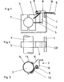
- the gripper finger 2 cooperating with the gripper support 1 can be formed in one piece as a sheet metal part by means of links 11, 12 preloaded via stop screw 8 and stop 13, which are elastically deformable.
- the handlebars 11, 12 are with a clamp piece firmly connected, which consists of preformed intertwined sheet metal strips 14, 15 which can be clamped on the gripper shaft 7 by means of a screw.
- the links 11, 12 must also control a vertical movement or slight pulling movement of the gripper finger 2 in a second movement phase, which is similar to the movement that is generated by resilient guide elements in the form of leaf springs.
- corresponding connecting lines of the links 11, 12 are provided, which likewise run through the fixed axis of the gripper shaft 7.
Landscapes
- Supply, Installation And Extraction Of Printed Sheets Or Plates (AREA)
- Feeding Of Articles By Means Other Than Belts Or Rollers (AREA)
- Discharge By Other Means (AREA)
Priority Applications (1)
| Application Number | Priority Date | Filing Date | Title |
|---|---|---|---|
| AT86110488T ATE46859T1 (de) | 1985-08-19 | 1986-07-30 | Federnder greifer fuer bogenrotationsdruckmaschinen. |
Applications Claiming Priority (2)
| Application Number | Priority Date | Filing Date | Title |
|---|---|---|---|
| DE19853529612 DE3529612A1 (de) | 1985-08-19 | 1985-08-19 | Federnder greifer fuer bogenrotationsdruckmaschinen |
| DE3529612 | 1985-08-19 |
Publications (3)
| Publication Number | Publication Date |
|---|---|
| EP0212366A2 true EP0212366A2 (fr) | 1987-03-04 |
| EP0212366A3 EP0212366A3 (en) | 1987-11-04 |
| EP0212366B1 EP0212366B1 (fr) | 1989-10-04 |
Family
ID=6278821
Family Applications (1)
| Application Number | Title | Priority Date | Filing Date |
|---|---|---|---|
| EP86110488A Expired EP0212366B1 (fr) | 1985-08-19 | 1986-07-30 | Pince à ressort pour rotatives à feuille |
Country Status (5)
| Country | Link |
|---|---|
| US (1) | US4719854A (fr) |
| EP (1) | EP0212366B1 (fr) |
| JP (1) | JPS6251448A (fr) |
| AT (1) | ATE46859T1 (fr) |
| DE (1) | DE3529612A1 (fr) |
Families Citing this family (8)
| Publication number | Priority date | Publication date | Assignee | Title |
|---|---|---|---|---|
| DE3806526A1 (de) * | 1988-03-01 | 1989-09-14 | Heidelberger Druckmasch Ag | Vorrichtung zum spannen von biegsamen druckplatten am plattenzylinder von rotationsdruckmaschinen |
| DE4101987A1 (de) * | 1991-01-24 | 1992-07-30 | Roland Man Druckmasch | Bogengreifereinrichtung an bogen-rotationsdruckmaschinen |
| DE4127713C2 (de) * | 1991-08-22 | 1996-03-21 | Koenig & Bauer Albert Ag | Greifer für Bogenrotationsdruckmaschinen |
| GB2268928B (en) * | 1992-07-22 | 1995-10-18 | Heidelberger Druckmasch Ag | Sheet gripper for a paper-carrying cylinder of a sheet-fed printing press |
| DE19816512B4 (de) | 1997-08-18 | 2008-08-28 | Heidelberger Druckmaschinen Ag | Bogengreifer in einer Bogenrotationsdruckmaschine |
| DE102007005958B4 (de) * | 2006-02-20 | 2015-07-16 | Heidelberger Druckmaschinen Ag | Vorrichtung zum Bogentransport |
| CN101024328B (zh) | 2006-02-20 | 2010-12-15 | 海德堡印刷机械股份公司 | 用于传送纸张的装置 |
| DE102009027508A1 (de) * | 2009-07-07 | 2011-01-20 | Manroland Ag | Greifer einer bogenhandhabenden Maschine |
Family Cites Families (18)
| Publication number | Priority date | Publication date | Assignee | Title |
|---|---|---|---|---|
| DD66634A (fr) * | ||||
| DD67992A (fr) * | ||||
| DE371756C (de) * | 1923-03-21 | Schnellpressenfabrik Act Ges H | Auf der Greiferstange drehbar angeordneter Greifer fuer An- und Ablegevorrichtungen sowie fuer Druckzylinder an Druckmaschinen | |
| DE356241C (de) * | 1920-02-22 | 1922-07-18 | Maschf Augsburg Nuernberg Ag | Greifer fuer die Druckzylinder von Druckmaschinen |
| DE670298C (de) * | 1937-02-28 | 1939-01-16 | Albert Schnellpressen | Auf einer verschwenkbaren Spindel lose angeordneter Bogengreifer fuer Druckmaschinen |
| US2378478A (en) * | 1943-02-18 | 1945-06-19 | Goss Printing Press Co Ltd | Printing press gripper mechanism |
| SU67992A1 (ru) | 1945-10-16 | 1946-11-30 | И.Н. Новиков | Устройство дл подрессоривани повозок |
| US2906204A (en) * | 1957-06-24 | 1959-09-29 | Cottrell Company | Gripper assemblies |
| US2935937A (en) * | 1957-10-29 | 1960-05-10 | Davidson Corp | Plate clamp for printing machine |
| US3044771A (en) * | 1960-04-18 | 1962-07-17 | Harris Intertype Corp | Sheet handling cylinder |
| AT298522B (de) * | 1968-02-21 | 1972-04-15 | Polygraph Leipzig | Vorrichtung zum klemmen von materialbogen |
| US3536321A (en) * | 1968-06-13 | 1970-10-27 | Planeta Veb Druckmasch Werke | Device for clamping sheet material |
| DE1908181A1 (de) * | 1969-02-19 | 1970-11-05 | Roland Offsetmaschf | Klemmgreifer fuer Bogenrotationsdruckmaschinen |
| US3606308A (en) * | 1969-06-20 | 1971-09-20 | Miller Printing Machinery Co | Sheet gripping device |
| ES230780Y (es) * | 1977-08-26 | 1978-07-01 | Conjunto de pinza y abrazadera para el transporte de laminasen maquinas litograficas. | |
| DD154083A1 (de) * | 1980-11-17 | 1982-02-24 | Arndt Jentzsch | Bogengreifereinrichtung |
| DE3267440D1 (en) * | 1981-09-04 | 1985-12-19 | Motter Printing Press Co | Gripper for sheet handling equipment |
| US4647031A (en) * | 1985-07-22 | 1987-03-03 | The Dow Chemical Company | Gripper finger device |
-
1985
- 1985-08-19 DE DE19853529612 patent/DE3529612A1/de active Granted
-
1986
- 1986-07-30 EP EP86110488A patent/EP0212366B1/fr not_active Expired
- 1986-07-30 AT AT86110488T patent/ATE46859T1/de not_active IP Right Cessation
- 1986-07-31 US US06/892,149 patent/US4719854A/en not_active Expired - Fee Related
- 1986-08-18 JP JP61191792A patent/JPS6251448A/ja active Granted
Also Published As
| Publication number | Publication date |
|---|---|
| JPH0530383B2 (fr) | 1993-05-07 |
| EP0212366A3 (en) | 1987-11-04 |
| JPS6251448A (ja) | 1987-03-06 |
| DE3529612A1 (de) | 1987-02-26 |
| EP0212366B1 (fr) | 1989-10-04 |
| ATE46859T1 (de) | 1989-10-15 |
| US4719854A (en) | 1988-01-19 |
| DE3529612C2 (fr) | 1990-01-18 |
Similar Documents
| Publication | Publication Date | Title |
|---|---|---|
| EP0213397B1 (fr) | Pince à ressort pour rotatives à feuille | |
| DD154083A1 (de) | Bogengreifereinrichtung | |
| EP0212368B1 (fr) | Pince à ressort pour rotatives à feuille | |
| EP0261412B1 (fr) | Pince pour machines rotatives à feuilles | |
| EP0212366A2 (fr) | Pince à ressort pour rotatives à feuille | |
| DE3830946C2 (fr) | ||
| DE4230218C2 (de) | Vorgreifer einer Bogendruckmaschine | |
| EP0213398B1 (fr) | Pince à ressort pour rotatives à feuille | |
| EP0933203A1 (fr) | Pince à dépression pour transférer le bord postérieur d'une feuille dans une machine à imprimer des feuilles rotative | |
| DD258211A1 (de) | Einrichtung zum steuern der greifer eines vorgreifers in bogenverarbeitenden maschinen | |
| DE3632768C1 (de) | Klemmgreifer fuer Bogenrotationsdruckmaschinen | |
| EP0212367A2 (fr) | Pince à ressort pour rotatives à feuille | |
| EP0250963A2 (fr) | Dispositif d'entraînement des pinces oscillantes d'une machine à imprimer | |
| DE4009175A1 (de) | Elastische hubduesen und tasterlagerung fuer bogenanleger | |
| DE19611124B4 (de) | Bogenübertragungseinrichtung einer Bogenrotationsdruckmaschine | |
| EP0803457B1 (fr) | Dispositif pour séparer et soulever la feuille de dessus d'une pile de feuilles | |
| DE102004060646A1 (de) | Bogenpositioniervorrichtung einer Bogenzuführeinrichtung von einer Druckerpresse | |
| DE3011365C2 (fr) | ||
| EP0402615B1 (fr) | Pince pour feuilles dans des machines travaillant avec des feuilles | |
| EP0560102B1 (fr) | Dispositif pour l'entraînement à sa périphérie d'un rouleau de matériau en bande | |
| DE3852058T2 (de) | Siebdruckmaschine. | |
| AT240322B (de) | Vorrichtung zum selbsttätigen Geradeführen von Gewebebahnen in Textilmaschinen | |
| DE8523759U1 (de) | Federnder Greifer für Bogenrotationsdruckmaschinen | |
| DE202023105035U1 (de) | Vorrichtung zur Lagerung eines Druckzylinders | |
| DE2360241C3 (de) | Einrichtung zum schrittweisen Vorschieben von Band- oder Streifenmaterial, an Pressen, Stanzen oder ähnlichen Arbeitsmaschinen |
Legal Events
| Date | Code | Title | Description |
|---|---|---|---|
| PUAI | Public reference made under article 153(3) epc to a published international application that has entered the european phase |
Free format text: ORIGINAL CODE: 0009012 |
|
| AK | Designated contracting states |
Kind code of ref document: A2 Designated state(s): AT CH FR GB IT LI NL SE |
|
| PUAL | Search report despatched |
Free format text: ORIGINAL CODE: 0009013 |
|
| AK | Designated contracting states |
Kind code of ref document: A3 Designated state(s): AT CH FR GB IT LI NL SE |
|
| 17P | Request for examination filed |
Effective date: 19870930 |
|
| 17Q | First examination report despatched |
Effective date: 19880526 |
|
| ITF | It: translation for a ep patent filed | ||
| GRAA | (expected) grant |
Free format text: ORIGINAL CODE: 0009210 |
|
| AK | Designated contracting states |
Kind code of ref document: B1 Designated state(s): AT CH FR GB IT LI NL SE |
|
| REF | Corresponds to: |
Ref document number: 46859 Country of ref document: AT Date of ref document: 19891015 Kind code of ref document: T |
|
| ET | Fr: translation filed | ||
| GBT | Gb: translation of ep patent filed (gb section 77(6)(a)/1977) | ||
| PLBE | No opposition filed within time limit |
Free format text: ORIGINAL CODE: 0009261 |
|
| STAA | Information on the status of an ep patent application or granted ep patent |
Free format text: STATUS: NO OPPOSITION FILED WITHIN TIME LIMIT |
|
| 26N | No opposition filed | ||
| ITTA | It: last paid annual fee | ||
| EAL | Se: european patent in force in sweden |
Ref document number: 86110488.3 |
|
| PGFP | Annual fee paid to national office [announced via postgrant information from national office to epo] |
Ref country code: CH Payment date: 19950614 Year of fee payment: 10 |
|
| PGFP | Annual fee paid to national office [announced via postgrant information from national office to epo] |
Ref country code: AT Payment date: 19950620 Year of fee payment: 10 |
|
| PGFP | Annual fee paid to national office [announced via postgrant information from national office to epo] |
Ref country code: NL Payment date: 19950629 Year of fee payment: 10 |
|
| PGFP | Annual fee paid to national office [announced via postgrant information from national office to epo] |
Ref country code: GB Payment date: 19960613 Year of fee payment: 11 |
|
| PGFP | Annual fee paid to national office [announced via postgrant information from national office to epo] |
Ref country code: FR Payment date: 19960617 Year of fee payment: 11 |
|
| PGFP | Annual fee paid to national office [announced via postgrant information from national office to epo] |
Ref country code: SE Payment date: 19960619 Year of fee payment: 11 |
|
| PG25 | Lapsed in a contracting state [announced via postgrant information from national office to epo] |
Ref country code: AT Effective date: 19960730 |
|
| PG25 | Lapsed in a contracting state [announced via postgrant information from national office to epo] |
Ref country code: LI Effective date: 19960731 Ref country code: CH Effective date: 19960731 |
|
| PG25 | Lapsed in a contracting state [announced via postgrant information from national office to epo] |
Ref country code: NL Effective date: 19970201 |
|
| REG | Reference to a national code |
Ref country code: CH Ref legal event code: PL |
|
| PG25 | Lapsed in a contracting state [announced via postgrant information from national office to epo] |
Ref country code: FR Effective date: 19970328 |
|
| NLV4 | Nl: lapsed or anulled due to non-payment of the annual fee |
Effective date: 19970201 |
|
| REG | Reference to a national code |
Ref country code: FR Ref legal event code: ST |
|
| PG25 | Lapsed in a contracting state [announced via postgrant information from national office to epo] |
Ref country code: GB Free format text: LAPSE BECAUSE OF NON-PAYMENT OF DUE FEES Effective date: 19970730 |
|
| PG25 | Lapsed in a contracting state [announced via postgrant information from national office to epo] |
Ref country code: SE Effective date: 19970731 |
|
| GBPC | Gb: european patent ceased through non-payment of renewal fee |
Effective date: 19970730 |
|
| EUG | Se: european patent has lapsed |
Ref document number: 86110488.3 |
|
| PG25 | Lapsed in a contracting state [announced via postgrant information from national office to epo] |
Ref country code: IT Free format text: LAPSE BECAUSE OF NON-PAYMENT OF DUE FEES;WARNING: LAPSES OF ITALIAN PATENTS WITH EFFECTIVE DATE BEFORE 2007 MAY HAVE OCCURRED AT ANY TIME BEFORE 2007. THE CORRECT EFFECTIVE DATE MAY BE DIFFERENT FROM THE ONE RECORDED. Effective date: 20050730 |