EP0212424A2 - Verbindungsleitungskopplungseinheit - Google Patents
Verbindungsleitungskopplungseinheit Download PDFInfo
- Publication number
- EP0212424A2 EP0212424A2 EP86110809A EP86110809A EP0212424A2 EP 0212424 A2 EP0212424 A2 EP 0212424A2 EP 86110809 A EP86110809 A EP 86110809A EP 86110809 A EP86110809 A EP 86110809A EP 0212424 A2 EP0212424 A2 EP 0212424A2
- Authority
- EP
- European Patent Office
- Prior art keywords
- terminals
- relays
- terminal
- relay
- signal
- Prior art date
- Legal status (The legal status is an assumption and is not a legal conclusion. Google has not performed a legal analysis and makes no representation as to the accuracy of the status listed.)
- Granted
Links
- 230000008878 coupling Effects 0.000 title claims description 9
- 238000010168 coupling process Methods 0.000 title claims description 9
- 238000005859 coupling reaction Methods 0.000 title claims description 9
- 230000005540 biological transmission Effects 0.000 claims description 35
- 230000000295 complement effect Effects 0.000 claims 1
- 208000032366 Oversensing Diseases 0.000 description 12
- 239000004020 conductor Substances 0.000 description 8
Images

Classifications
-
- H—ELECTRICITY
- H04—ELECTRIC COMMUNICATION TECHNIQUE
- H04L—TRANSMISSION OF DIGITAL INFORMATION, e.g. TELEGRAPHIC COMMUNICATION
- H04L12/00—Data switching networks
- H04L12/28—Data switching networks characterised by path configuration, e.g. LAN [Local Area Networks] or WAN [Wide Area Networks]
- H04L12/42—Loop networks
-
- F—MECHANICAL ENGINEERING; LIGHTING; HEATING; WEAPONS; BLASTING
- F02—COMBUSTION ENGINES; HOT-GAS OR COMBUSTION-PRODUCT ENGINE PLANTS
- F02F—CYLINDERS, PISTONS OR CASINGS, FOR COMBUSTION ENGINES; ARRANGEMENTS OF SEALINGS IN COMBUSTION ENGINES
- F02F1/00—Cylinders; Cylinder heads
- F02F1/24—Cylinder heads
- F02F2001/241—Cylinder heads specially adapted to pent roof shape of the combustion chamber
Definitions
- TCU trunk coupling unit
- the TCUs are provided in correspondence to a plurality of individual stations and each serves for switching or controlling the data transfer between a ring-like transmission path and the associated station.
- the TCU When the associated station is to be connected to the transmission path, the TCU operates to break the transmission path and connect one end of the broken transmission path to the input terminal of the associated station while connecting the other end of the broken transmission path to the output terminal of that station. On the other hand, when the associated station is to be disconnected from the transmission path, both the ends of the broken transmission path are again connected to each other and both the terminals of the station are interconnected.
- the TCU includes a number of relay circuits.
- the TCU of the hitherto known structure suffers a difficulty in that cross-talk takes place through the relay circuits provided internally of the TCU.
- cross-talk takes place through the relay circuits provided internally of the TCU.
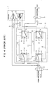
- Fig. 3 is a view for illustrating the occurrence of cross-talk upon connection of a station l to a transmission path 3 through an associated TCU 2.
- each of relays 6, 7 and 8 has terminals a , b , and c , wherein the terminal a is selectively connected to either the terminal b or terminal c for connecting the station l to the transmission path 3 or disconnecting the former from the latter.
- a reference numeral l0 denotes a wiring conductor for establishing a connection between the terminals b of the relays 6 and 7, a numeral ll denotes a wiring conductor for forming connection between the terminals c of the relays 6 and 7, a numeral l2 denotes a wiring conductor for realizing connection between the terminals b of the relays 8 and 9, and a numeral l3 denotes a wiring conductor for the connection between the terminals c of the relays 8 and 9.
- an incoming signal A produced by a transmitter 5 of a preceding station l (not shown) is sent through its associated TCU to a receiver 4 of the illustrated station l through its relays 6 and 8.
- a signal B produced by the transmitter 5 of the station l is sent through the relays 7 and 9 to the transmission path leading to a TCU of a succeeding station (not shown).
- positive cross-talks C(+) of the signal B take place to the terminals c from the terminals b of the relays 6 and 7, respectively, to which the positive polarity of the signal is applied, both cross-talks being added together to be of a magnitude 2C(+) assuming that C(+) also represents the magnitude of each cross-talk.
- negative cross-talks C(-) each having the same magnitude as C(+) and a polarity opposite to that of the latter, take place from the terminals b to the terminals c of the relays 8 and 9, respectively, to which the negative polarity of the signal is applied. Both the negative cross-talks are added together to be 2C(-). In this case, when the signal A becomes quiescent, the cross-talks 2C(+) and 2C(-) of opposite polarities are reproduced by the receiver 4 of the station l, bringing about erroneous operation.
- Fig. 4 is a view for illustrating the occurrence of cross-talk upon disconnection of the station l from the transmission path 3 through the associated TCU l.
- like parts as those shown in Fig. 3 are denoted by like reference symbols.
- a signal D sent out from the transmitter 5 of the station l is fed to the receiver 4 thereof through the relays 7 and 9 and the relays 6 and 8.
- an incoming signal E derived from the TCU of the preceding stage through the incoming transmission path 3 is sent through the relays 6 and 8 and the relays 7 and 9 to the outgoing transmission path leading to the TCU of the succeeding stage.
- positive cross-talks F(+) of the signal E takes place from the terminals c of the relays 6 and 7 to the terminals b thereof, respectively, which are added together to be 2F(+).
- An object of the present invention is to provide a trunk coupling unit of such a structure that the cross-talks taking place in the relay circuits are mutually cancelled.
- the present invention starts from recognition of the fact that a differential Manchester code recommended as a code for transmission in IEEE Standard 802.5 is insusceptible to the polarity of the code and provides no problem upon exchange of signal lines and provides such that the relays are so connected that some of the signals are inverted in the polarity to thereby allow the cross-talks of different polarities to be cancelled out through addition to each other.
- a trunk coupling unit which comprises a relay circuit composed of first and second relays of which respective terminals may suffer from cross-talk signals of positive polarity when a signal of a positive polarity is applied to opposite terminals thereof which are in the make state and in the break state, respectively, and third and fourth relays of which respective terminals may suffer from cross-talk signals of negative polarity when a signal of a negative polarity is applied to opposite terminals thereof, which are in the make state and in the break state, respectively, wherein the terminals of the first and fourth relays at which the cross-talk signal may appear are interconnected, while the terminals of the second and third relays at which the cross-talk signal may appear are interconnected.
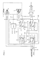
- a TCU 20 shown in Figs. l and 2 corresponds to the TCU 2 described hereinbefore in conjunction with Figs. 3 and 4 except for an improvement on the structure of the relay circuit made according to the invention.
- a driver circuit l6 produces control signals S and to relays 6 to 9 in response to a command l7 produced by the associated station l.
- the signal S is turned on to thereby set the relays 6 and 8 in the break state (i.e. the state in which the contact between the terminals a and c is closed, while the signal S is turned off to set the relays 7 and 9 in the make state (i.e. the state in which the contact between the terminals a and c is opened).
- the command l7 indicates that the station l is to be disconnected from the transmission path
- the signal S is turned off to set the relays 6 and 8 in the make state with the relays 7 and 9 being set in the break state.
- the wiring of the relays shown in Figs. l and 2 differs from the one shown in Figs. 3 and 4 in that the terminals c of the relays 6 and 9 are connected to each other by a wiring conductor l4, while the terminals c of the relays 7 and 8 are connected to each other by a wiring conductor l5.
- an incoming signal A from the TCU of the preceding stage is sent to the receiver 4 of the station l through the relays 6 and 8.
- a signal B generated by the transmitter 5 of the station l is sent to the outgoing transmission path leading to the TCU of the succeeding stage through the relays 7 and 9.
- positive cross-talk C(+) of the signal B is introduced to the terminals c from the terminal b , respectively, of the relays 6 and 7.
- negative cross-talk C(-) of the signal B is introduced from the terminals b to the terminal c , respectively, of the relays 8 and 9.
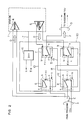
- the signal D generated by the transmitter 5 of the station l is sent to the receiver 4 of the same station by way of the relays 7 and 9 and the relays 6 and 8.
- the incoming signal E from the TCU of the preceding station through the transmission path 3 is transferred onto the outgoing transmission path leading to the TCU of the succeeding station through the relays 6 and 8 and the relays 7 and 9.
- positive cross-talk F(+) is introduced from the terminals c to the terminals b in the relays 6 and 9, respectively.
- negative cross-talk F(-) is introduced from the terminals c to the terminals b in the relays 7 and 8, respectively.
Landscapes
- Engineering & Computer Science (AREA)
- Computer Networks & Wireless Communication (AREA)
- Signal Processing (AREA)
- Cable Transmission Systems, Equalization Of Radio And Reduction Of Echo (AREA)
- Small-Scale Networks (AREA)
Applications Claiming Priority (2)
| Application Number | Priority Date | Filing Date | Title |
|---|---|---|---|
| JP181807/85 | 1985-08-21 | ||
| JP60181807A JPS6243236A (ja) | 1985-08-21 | 1985-08-21 | リレー結線回路 |
Publications (3)
| Publication Number | Publication Date |
|---|---|
| EP0212424A2 true EP0212424A2 (de) | 1987-03-04 |
| EP0212424A3 EP0212424A3 (en) | 1988-07-13 |
| EP0212424B1 EP0212424B1 (de) | 1990-04-25 |
Family
ID=16107185
Family Applications (1)
| Application Number | Title | Priority Date | Filing Date |
|---|---|---|---|
| EP86110809A Expired EP0212424B1 (de) | 1985-08-21 | 1986-08-05 | Verbindungsleitungskopplungseinheit |
Country Status (4)
| Country | Link |
|---|---|
| US (1) | US4697047A (de) |
| EP (1) | EP0212424B1 (de) |
| JP (1) | JPS6243236A (de) |
| DE (1) | DE3670743D1 (de) |
Cited By (4)
| Publication number | Priority date | Publication date | Assignee | Title |
|---|---|---|---|---|
| GB2265069A (en) * | 1992-03-11 | 1993-09-15 | Soundcraft Electronics Ltd | Reducing crosstalk in networks |
| EP0573736A3 (en) * | 1992-06-12 | 1995-08-23 | Univ Res Ass Inc | Switch for serial or parallel communication networks |
| GB2316839A (en) * | 1996-08-26 | 1998-03-04 | Sony Trans Com Inc | Serial data bus segmentation |
| US7526350B2 (en) | 2003-08-06 | 2009-04-28 | Creative Technology Ltd | Method and device to process digital media streams |
Families Citing this family (4)
| Publication number | Priority date | Publication date | Assignee | Title |
|---|---|---|---|---|
| US4803485A (en) * | 1987-03-23 | 1989-02-07 | Amp Incorporated | Lan communication system and medium adapter for use therewith |
| JP2509632B2 (ja) * | 1987-09-07 | 1996-06-26 | 株式会社東芝 | デ―タ入出力装置 |
| US5132832B1 (en) * | 1990-12-18 | 1995-04-18 | Amp Inc | Token ring concentration with global reset capability |
| US5199026A (en) * | 1991-02-27 | 1993-03-30 | Memorex Telex N.V. | Token ring wiring concentrator |
Family Cites Families (1)
| Publication number | Priority date | Publication date | Assignee | Title |
|---|---|---|---|---|
| JPS55102989A (en) * | 1979-01-30 | 1980-08-06 | Nec Corp | Crosstalk reduction circuit |
-
1985
- 1985-08-21 JP JP60181807A patent/JPS6243236A/ja active Granted
-
1986
- 1986-08-01 US US06/891,886 patent/US4697047A/en not_active Expired - Lifetime
- 1986-08-05 DE DE8686110809T patent/DE3670743D1/de not_active Expired - Lifetime
- 1986-08-05 EP EP86110809A patent/EP0212424B1/de not_active Expired
Non-Patent Citations (1)
| Title |
|---|
| IBM TECHNICAL DISCLOSURE BULLETIN, vol. 26, no. 2, July 1983, pages 805-808, New York, US; E.J. ANNUNZIATA et al.: "Automatic port location identification mechanism" * |
Cited By (7)
| Publication number | Priority date | Publication date | Assignee | Title |
|---|---|---|---|---|
| GB2265069A (en) * | 1992-03-11 | 1993-09-15 | Soundcraft Electronics Ltd | Reducing crosstalk in networks |
| GB2265069B (en) * | 1992-03-11 | 1995-10-04 | Soundcraft Electronics Ltd | Improvements in or relating to networks |
| EP0573736A3 (en) * | 1992-06-12 | 1995-08-23 | Univ Res Ass Inc | Switch for serial or parallel communication networks |
| GB2316839A (en) * | 1996-08-26 | 1998-03-04 | Sony Trans Com Inc | Serial data bus segmentation |
| GB2316839B (en) * | 1996-08-26 | 2001-04-04 | Sony Trans Com Inc | Serial data bus segmentation systems |
| US7526350B2 (en) | 2003-08-06 | 2009-04-28 | Creative Technology Ltd | Method and device to process digital media streams |
| US8954174B2 (en) | 2003-08-06 | 2015-02-10 | Creative Technology Ltd | Method and device to process digital media streams |
Also Published As
| Publication number | Publication date |
|---|---|
| JPS6243236A (ja) | 1987-02-25 |
| US4697047A (en) | 1987-09-29 |
| JPH0347789B2 (de) | 1991-07-22 |
| DE3670743D1 (de) | 1990-05-31 |
| EP0212424A3 (en) | 1988-07-13 |
| EP0212424B1 (de) | 1990-04-25 |
Similar Documents
| Publication | Publication Date | Title |
|---|---|---|
| JPH1197124A (ja) | 高速伝送方式及びコネクタ | |
| GB2281476A (en) | Digital switching system connecting buses with incompatible protocols and telephone answering system | |
| US4697047A (en) | Trunk coupling unit | |
| JPS6228904B2 (de) | ||
| US4847611A (en) | Ring configuration of line concentrators | |
| EP0032992B1 (de) | Schaltungsanordnung zum Übergang einer mit Halbduplex arbeitenden, digitale Daten übertragenden, Leitung in eine Simplex-Sende- und eine Simplex-Empfangsleitung und umgekehrt | |
| JPH04247742A (ja) | バス線終端方式 | |
| US4115849A (en) | Data interface bridge | |
| JP3068125B2 (ja) | バス型光伝送路用通信局 | |
| JPS63276151A (ja) | 二重化装置切替方式 | |
| JPS60500233A (ja) | 遠隔通信端末 | |
| JPS58172039A (ja) | 光伝送システム | |
| JPH0247581Y2 (de) | ||
| JPS59218063A (ja) | デ−タ伝送装置 | |
| JP2969748B2 (ja) | インタフェース制御方式 | |
| JPS60170396A (ja) | 中継接続方式 | |
| JPS62256066A (ja) | 端末装置 | |
| JPS577655A (en) | General multiple address transmission system | |
| JPH0131739B2 (de) | ||
| JPH07240759A (ja) | 伝送システム | |
| JPS62221234A (ja) | 回線変換装置 | |
| WO1992000564A1 (en) | Circuit for alternately connecting one of several data lines to a common data read line | |
| JPS61257029A (ja) | 半二重通信用通信機 | |
| JPH0652904B2 (ja) | 信号分岐方式 | |
| JPS5825743A (ja) | デ−タ送受信回路 |
Legal Events
| Date | Code | Title | Description |
|---|---|---|---|
| PUAI | Public reference made under article 153(3) epc to a published international application that has entered the european phase |
Free format text: ORIGINAL CODE: 0009012 |
|
| AK | Designated contracting states |
Kind code of ref document: A2 Designated state(s): CH DE GB LI |
|
| PUAL | Search report despatched |
Free format text: ORIGINAL CODE: 0009013 |
|
| AK | Designated contracting states |
Kind code of ref document: A3 Designated state(s): CH DE GB LI |
|
| 17P | Request for examination filed |
Effective date: 19880720 |
|
| 17Q | First examination report despatched |
Effective date: 19881017 |
|
| RBV | Designated contracting states (corrected) |
Designated state(s): DE GB |
|
| GRAA | (expected) grant |
Free format text: ORIGINAL CODE: 0009210 |
|
| AK | Designated contracting states |
Kind code of ref document: B1 Designated state(s): DE GB |
|
| REF | Corresponds to: |
Ref document number: 3670743 Country of ref document: DE Date of ref document: 19900531 |
|
| PLBE | No opposition filed within time limit |
Free format text: ORIGINAL CODE: 0009261 |
|
| STAA | Information on the status of an ep patent application or granted ep patent |
Free format text: STATUS: NO OPPOSITION FILED WITHIN TIME LIMIT |
|
| 26N | No opposition filed | ||
| PGFP | Annual fee paid to national office [announced via postgrant information from national office to epo] |
Ref country code: GB Payment date: 20010726 Year of fee payment: 16 |
|
| PGFP | Annual fee paid to national office [announced via postgrant information from national office to epo] |
Ref country code: DE Payment date: 20011030 Year of fee payment: 16 |
|
| REG | Reference to a national code |
Ref country code: GB Ref legal event code: IF02 |
|
| PG25 | Lapsed in a contracting state [announced via postgrant information from national office to epo] |
Ref country code: GB Free format text: LAPSE BECAUSE OF NON-PAYMENT OF DUE FEES Effective date: 20020805 |
|
| PG25 | Lapsed in a contracting state [announced via postgrant information from national office to epo] |
Ref country code: DE Free format text: LAPSE BECAUSE OF NON-PAYMENT OF DUE FEES Effective date: 20030301 |
|
| GBPC | Gb: european patent ceased through non-payment of renewal fee |
Effective date: 20020805 |