EP0212657B1 - Kompaktes Lagersystem - Google Patents
Kompaktes Lagersystem Download PDFInfo
- Publication number
- EP0212657B1 EP0212657B1 EP86111783A EP86111783A EP0212657B1 EP 0212657 B1 EP0212657 B1 EP 0212657B1 EP 86111783 A EP86111783 A EP 86111783A EP 86111783 A EP86111783 A EP 86111783A EP 0212657 B1 EP0212657 B1 EP 0212657B1
- Authority
- EP
- European Patent Office
- Prior art keywords
- guide rail
- storage system
- compact storage
- compact
- guide roller
- Prior art date
- Legal status (The legal status is an assumption and is not a legal conclusion. Google has not performed a legal analysis and makes no representation as to the accuracy of the status listed.)
- Expired - Lifetime
Links
- 238000003860 storage Methods 0.000 title claims description 173
- 239000000463 material Substances 0.000 claims description 4
- 238000005452 bending Methods 0.000 claims description 3
- 230000008878 coupling Effects 0.000 description 8
- 238000010168 coupling process Methods 0.000 description 8
- 238000005859 coupling reaction Methods 0.000 description 8
- 238000000429 assembly Methods 0.000 description 4
- 230000000712 assembly Effects 0.000 description 4
- 238000010276 construction Methods 0.000 description 4
- 230000004048 modification Effects 0.000 description 3
- 238000012986 modification Methods 0.000 description 3
- 229920004943 Delrin® Polymers 0.000 description 2
- 239000003831 antifriction material Substances 0.000 description 2
- 230000013011 mating Effects 0.000 description 2
- 239000004677 Nylon Substances 0.000 description 1
- XAGFODPZIPBFFR-UHFFFAOYSA-N aluminium Chemical compound [Al] XAGFODPZIPBFFR-UHFFFAOYSA-N 0.000 description 1
- 229910052782 aluminium Inorganic materials 0.000 description 1
- 230000009286 beneficial effect Effects 0.000 description 1
- 230000015572 biosynthetic process Effects 0.000 description 1
- 239000000356 contaminant Substances 0.000 description 1
- 230000001419 dependent effect Effects 0.000 description 1
- 238000001125 extrusion Methods 0.000 description 1
- 238000003197 gene knockdown Methods 0.000 description 1
- 239000004519 grease Substances 0.000 description 1
- 238000001764 infiltration Methods 0.000 description 1
- 230000008595 infiltration Effects 0.000 description 1
- 230000002452 interceptive effect Effects 0.000 description 1
- 238000005304 joining Methods 0.000 description 1
- 238000007567 mass-production technique Methods 0.000 description 1
- 229920001778 nylon Polymers 0.000 description 1
- 230000002093 peripheral effect Effects 0.000 description 1
- 238000005096 rolling process Methods 0.000 description 1
- 238000007665 sagging Methods 0.000 description 1
Images


Classifications
-
- A—HUMAN NECESSITIES
- A47—FURNITURE; DOMESTIC ARTICLES OR APPLIANCES; COFFEE MILLS; SPICE MILLS; SUCTION CLEANERS IN GENERAL
- A47B—TABLES; DESKS; OFFICE FURNITURE; CABINETS; DRAWERS; GENERAL DETAILS OF FURNITURE
- A47B53/00—Cabinets or racks having several sections one behind the other
- A47B53/02—Cabinet systems, e.g. consisting of cabinets arranged in a row with means to open or close passages between adjacent cabinets
Definitions
- the present invention relates to a compact storage system according to the definition of the species of claim 1 and to a compact storage system according to the definition of the species of claim 16.
- a compact storage system according to claim 1 is known from US-A-1 807 075 and a compact storage system according to claim 16 is known from DE-A-26 14 159.
- means for supporting a movable storage unit for translational movement on a floor of a room comprises means mounted with the movable storage unit, which roller means are guided by related rails being approximately flush with the upper face of the floor of the room.
- guide rail means mounted to span a distance between support means of the system in generally parallel relation to a base platform comprise rails, the profile of which is not defined. These rails guide rollers of movable storage units.
- Means for supporting the movable storage units for translational movement on said base platform comprises roller means mounted with said storage units for rolling movement on said base platform.
- US-A-3,570,683 discloses a movable support panel sample for hanging and supporting articles being of modular construction provided by a number of modules within an outer rectangular frame. Each module has a panel for supporting the articles, and the outer frame has roller supports at the bottom for moving the samply on the floor and guides at the side edges for extending into stationary overhead tracks. The guides may be retracted so that the assembly may be moved to positions which are not under the track. For such movements an outrigger transporter assembly is attached to each end of the screen.
- U.S. Patent No. 3,801,176 (Higbee) relates to a typical storage system of this type, which is also known as an "active aisle" system.
- the storage system shown in the Higbee patent includes a pair of inverted, generally V-shaped rails that are mutually parallel and are securely mounted on a base platform such as a floor.
- a number of storage units or carts are mounted on wheels, each of which has a V-shaped groove formed in its circumference.
- Two wheels on each cart mate with, and are guided on, one of the two V-shaped rails.
- the wheels on each cart are fixed against swiveling movement, which is said to eliminate the need for directly attaching the guide rails to the floor.
- the system shown in the Higbee patent has several notable disadvantages. More particularly, in applications in, for example, the food service and hospital industries, it is difficult to maintain sanitary conditions on and about the rails that are mounted on the floor since they readily collect undesirable foreign matter such as dirt and grease.
- the rails mounted on the floor also may constitute a safety hazard since operators and users of the system may trip or stumble over them. Additionally, users of the system may want to take independent wheeled utility carts into the active aisle to transport items to and from the storage units. However, guide rails mounted on the floor interfer with free movement of such utility carts into the active aisle.
- the object of the present invention is to present a compact storage system of the type defined in the conception of claim 1 which incorporates a novel guide rail and mating guide roller configuration that facilitates ease of operation.
- the compact storage system of the present invention eliminates the disadvantages of the prior art which incorporate floor-mounted guide rails. Moreover, in its preferred embodiment, the present invention also eliminates disadvantages of prior art systems which, while providing guides at the top of each storage unit, are difficult to install and assemble.
- the system of the present invention may also be installed at any location having a generally flat floor without modification of the building or other surrounding structures. That is, this storage system may be completely self contained and need not be permanently attached to any surrounding structure, even though in some applications it may be desirable to do so.
- the compact storage system of the present invention includes at least two end supports positioned in spaced relation on the floor or base platform. At least one guide rail is mounted to span the distance between these supports and is thereby mounted in generally parallel relation to the floor.
- the guide rail has a roof and two legs depending from the roof toward the base platform thereby to define a continuous U-shaped channel that is inverted or open downwardly.
- a number of movable storage units are mounted for translational movement between the supports.
- Each of the storage units is mounted for translational movement on the base platform or floor between the two supports and the total width of all of the movable storage units is less than the distance between the two supports.
- Guide rollers are mounted on each of the movable storage units and are received in the channel of the guide rail.
- each storage unit is confined by the guide rails and any two of the storage units can be moved to positions closely adjacent each other with a space for an access aisle remaining adjacent at least one of the two movable storage units.
- the system of the present invention may be assembled by positioning all storage units on the base platform, mounting the end supports at the outer extremes of the storage units, and then mounting the guide rail in position between the supports and over the guide rollers on each storage unit.
- the storage units need not be lifted to engage guide rollers and guide rails in order to complete the assembly;
- the guide rails need not be positioned under complimentary guide rollers after the storage units are in place; and the guide rollers need not be mounted on the storage units after the guide rails are in place.
- the rails need not be secured in complicated fashion to an existing building structure.
- each guide rail is also quite deep compared to the height of the guide rollers. Therefore, interengagement of the rail and roller can be maintained even if the floor or base platform is not flat or the guide rail deviates from a straight line, for example by sagging.
- the high density or compact storage system makes most efficient use of available floor space by providing storage units that are movable in such a way so as to define a single movable access aisle for all of the units. That is, any two movable storage units may be positioned to be directly adjacent each other at one side of each with access provided by an aisle on an opposite side of one of the units. If access is desired on the other side of that unit, initially directly adjacent the other unit, the first unit is merely moved to a position spaced from the other unit thereby moving the access aisle.
- the present invention has particular utility as a compact storage unit that utilizes, as its basic components, a wire shelving system known as the SUPER ERECTA shelf system made and sold by InterMetro Industries, the assignee of the subject invention.
- a wire shelving system known as the SUPER ERECTA shelf system made and sold by InterMetro Industries, the assignee of the subject invention.
- the novel components of the subject invention may be used equally well in other storage systems in which the storage units are constructed in many different fashions.
- the present invention provides particular advantages in application such as in the food service and hospital industries where sanitation is of prime concern.
- Fig. 1 is a perspective view of a compact storage system constructed and assembled in accordance with a preferred embodiment of the present invention.
- Fig. 2 is a side elevational view taken partly in vertical cross-section of the compact storage system shown in Fig. 1.
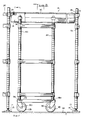
- Fig. 3 is a vertical cross-sectional view taken on plane 3-3 in Fig. 2.
- Fig. 4 is a perspective view of the end of a guide rail of the compact storage system of the present invention and of a coupling member for mounting it with stationary supports above the base platform.
- Fig. 5 is an exploded perspective view of two guide rails and of a link element for joining them together.
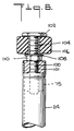
- Fig. 6 is a cross-selemental view of an alternative guide roller construction
- the compact storage system of the present invention is particularly well adapted for use in conjunction with a knock-down shelving system known as the SUPER ERECTA shelf system manufactured and sold by InterMetro Industries Corporation.
- the general principle of the subject invention may readily be incorporated in other systems using storage units of different constructions than the SUPER ERECTA shelf system. Nevertheless, for convenience, the present invention will be described in conjunction with that system.
- U.S. Patent Nos. 3,424,111 (Maslow) and 3,757,705 (Maslow) the disclosures of each of which are incorporated herein by a reference. Details of that system that do not form a part of the subject invention will not be described herein.
- the compact storage system of the present invention includes two spaced stationary support structures 12, each respectively including four corner posts 14 and a number of shelves 16 that are supported on the four corner posts 14.
- Each corner post 14 can be provided with a leveling foot assembly 15 comprising a threaded stem 17 mating with a thread plug (not shown) secured within the bottom end of each post 14.
- the support structures 12 are positioned so that the respective sides of each lie generally in the same plane.
- this storage unit includes four corner posts 24 on which are mounted a number of shelves 26.
- a wheel 28 is mounted, with its axis extending generally perpendicularly to the plane defined by the sides of the support structures, at the bottom of each corner post 24 of the storage unit 22. Accordingly, the storage unit may be freely rolled for translational movement between the support structures.
- the storage unit and support structures utilize shelves having the same dimensions. Accordingly, the corner posts are spaced apart in the direction of the length of both the storage unit and support structures by the same distance L. Therefore, respective pairs of corner posts of the storage unit, on each side thereof, are aligned with one guide rail 18 extending between the support structures.
- Each of the corner posts of the storage unit is provided at its top with a guide roller, to be described below in detail, that is received within one of the guide rails so that movement of the rollers and hence translational movement of the support structure is confined to a path defined by the guide rails.
- the guide rails are mounted above, rather than below, the storage units, it is not necessary to lift the storage units onto floor mounted rails nor, as explained in greater detail below, is it necessary to lift the storage units or otherwise use complex assembly steps to suspend guide rollers from guide rails mounted above the storage unit. Also, as will be described in greater detail below, the design of the guide rails and rollers accommodate irregularities in the base platform and guide rail while reliably guiding the storage unit for movement.
- any two storage units or any one storage unit and a support structure may be positioned closely adjacent each other with a space remaining between the one of those storage units and another thereof. This space is the so-called "active aisle", that can be shifted to provide access to any side of any storage unit while other storage units are moved to their closely adjacent space-saving positions.
- each guide rail 18 has a generally inverted U-shape that defines a continuous elongate, downwardly open channel 31.
- the U-shaped cross-section of the guide rail is defined by a roof 32 and two depending legs each generally indicated at 34, and has substantial height or depth compared to its width.
- each leg 34 comprises by a box beam that includes an inwardly facing vertical wall 40, a bottom wall 42 and an outer wall 44 at least part of which is upwardly inwardly sloped.
- each guide rail 18 may be extruded of, for example, aluminum with the box beam leg structure of the extrusion providing great resistance of bending thereof when mounted between the support structures.
- the external configuration of the guide rail is particularly well suited for applications of the compact storage system such as those that require sanitary conditions. More particularly, the external shape of the guide rail tends to shed foreign material, since there are no external crevices or other irregularities in the outer surface which would tend to trap and collect foreign contaminants.
- each guide rail 18 may be provided with an end cap 46 to enclose the open box beam legs 34 and prevent infiltration of foreign matter thereinto.
- end caps have the same peripheral configuration as the cross section of the guide rail.
- the guide rails are extruded with a small cylindrical channel 33 in the inner surface of the side walls 44 of the legs 34. The end caps can be secured to the rail by screws 35 threaded into these channels.
- the guide rails may also be equipped with coupling members 48 specifically designed to cooperate with corner posts of the InterMetro Industries SUPER ERECTA shelf system. More particularly, as described in U.S. Patents Nos. 3,424,111 (Maslow) and 3,757,705 (Maslow), each corner post is generally cylindrical and has regularly spaced annual grooves 50 in its outer surface. Each corner post cooperates with one or more collars 52 having a cylindrical inner surface and a frusto-conical outer surface. Each collar is adapted to mate with a sleeve 54 mounted at the corners of each shelf and having a complimentary frusto-conical inner surface.
- the inner surface of the collar also is formed with an annular rib that interfits with any one of the annular grooves 50 in the corner post. Accordingly, when a shelf having the frusto-conical sleeves at its corners is mounted with the sleeves telescopically received about the collars mounted on the corner parts, load on the shelf tends to cause the collars to collapse radially inwardly toward the respective corner posts thereby securely mounting the collar, and hence the sleeve, to the post and thereby to support the shelf.
- Each coupling member 48 for the guide rails makes use of this corner post, collar, and sleeve configuration. More particularly, as shown in Fig.
- each coupling member 48 is formed with a sleeve 56 having a frusto-conical inner surface that mates with one collar 52 carried on a corner post.
- An inverted U-shaped arm 58 projects radially away from the sleeve and engages the inner wall 36 of the roof 32 of the guide rail and the inner walls 40 of the legs 34 of that rail as can best be seen in Fig. 3.
- At least one bolt 60 passes through the roof of the guide rail and the arm 58 to secure the two tightly together.
- the coupling member 48 may also include a beam 59 extending from the sleeve 56 in a direction opposite the arm 58 to another corner post of a stationary storage unit 12.
- a similar sleeve 56 is mounted at the end of the beam 59 and is engaged with a collar on the other post in the same manner as described above. Accordingly, with the coupling member 48 mounted with the guide rail, and with the sleeves 56 of the coupling member received about collars mounted on the corner posts of the stationary storage unit, the weight of the guide rail similarly tends to cause the collars to collapse radially about the corner posts to securely mount the two together and thereby support the guide rail.
- end cap 46 for each guide rail is to be provided with a notch 62 that accommodates the arm 58 of the coupling member 48.
- link members 64 may also be provided to join two or more guide rails as shown in Figs. 1, 3 and 5.
- link members have a generally J-shaped cross section comprising a first major leg 66 formed to lie tightly against the inner surface of the inner wall 40 of a leg of the guide rail, a horizontal leg 68 formed to lie tightly against the inner surface of the bottom wall 42 or a leg of the guide rail, and a minor leg 70 formed to lie closely against the inner surface of the outer wall 34 a leg of the guide rail.
- These link members are secured to adjacent guide rails mounted together thereby by suitable bolts 72 passing through the bottom wall 42 and into a threaded insert 73 secured in the horizontal leg 68. It has been found that with guide rails made in eight (8) foot lengths, link members of two (2) foot lengths provide sufficient rigidity at the junction of two guide rails.
- each such guide roller 30 is mounted on a stub shaft 74 threaded into an end cap 75 secured within the upper portion of a corner post 24, for example, by a press fit.
- the axis of this stub shaft extends with the axis of the corner post.
- An antifriction bushing 77 may be provided between the roller 30 and the stub shaft 74 and an antifriction washer 79 can be mounted on either end of the roller all to permit the roller to freely rotate.
- the guide roller is adapted to rotate about the axis of the stub shaft and therefore its circumference can contact the inner surface of either inner wall 40 of the legs of the guide rail.
- the diameter of each guide roller is slightly smaller than the distance between opposing inner walls 40 of the guide rail. Accordingly, movement of each storage unit is confined by engagement of the guide rollers with the guide rails to a path defined by the guide rails.
- a cap nut 76 is mounted on the top of each stub shaft to retain the roller 30 thereof.
- This cap nut is either made of or coated with an antifriction material such as nylon. Accordingly, if there is any irregularity in the base platform or deflection of the guide rail which would cause the top of the cap nut to engage the inner wall 36 of the roof of the guide rail, the cap nut would nevertheless freely slide along that inner wall.
- FIG. 6 An alternative guide roller construction is shown in Fig. 6 and includes an end cap 75 having a thread bore 101 that again is secured in the top of each corner post 24 of each movable storage unit 22, for example, by being crimped therein.
- a threaded bolt 100 having a thin broad hexagonal head 102 is provided with a bushing 104, and a guide roller 106, also preferrably made of DELRIN material, is mounted about the bushing.
- the bushing has a slightly larger axial dimension than does the roller.
- the bushing is clamped between the head 102 of the bolt 100 and a flat washer 108 by a clamp nut 110 threaded onto the bolt 100. Therefore, the roller 106 can freely rotate on the bushing between the head 102 and the washer.
- the bolt 100 is mounted on the corner post by being threaded into the bore 101 of the end cap 75.
- the guide roller assembly including the bolt 100, bushing 104, washer 108, clamp nut 110, and guide roller 106 may be shipped to an end user in assembled form, while the corner posts 24 for the storage units are shipped with the end caps 75 secured in place.
- the end user can assemble the storage units from the bottom up with the shelves 26 mounted with the corner posts.
- the guide roller assemblies may be mounted on top of each corner post as described above and the system assembly can thereafter be completed.
- each wheel may comprise a caster assembly, generally indicated at 78, including the wheel 28, which is mounted on a horizontally extending shaft 80 spanning the distance between two legs 81 of a horn 82.
- the base 84 of the norm is provided with an upwardly projecting pin 86 that is received in a socket 88 fixed in the bottom of each corner post 24 of each storage unit 22.
- the axis of the pin 86 is offset with respect to the axis of the shaft 80, that is, the axes of the pin and shaft are skewed. Accordingly, each wheel is located so that its circumference lies substantially within the lateral extreme of each storage unit. Therefore, adjacent storage units may be rolled to positions abutting one another without their respective wheels interfering.
- the present invention also includes a structure for preventing the caster assembly 78 from swiveling in its socket 58 with respect to the corner posts 24.
- This structure confines the wheels such that the shaft of each extends generally perpendicularly to the plane defined by the sides of the storage unit and support structures.
- this structure comprises an inverted generally U-shaped channel 90 having length approximately equal to the width of a storage unit.
- the base 92 of the channel is formed with two holes 93 near its extremes each of which is concentric respectively with one pin of each caster when mounted in respective corner posts 24 of the storage unit.
- the sides 96 of the channel are spaced by a distance slightly greater than the width of the horn 82, namely the distance between the outer surfaces of the legs of the horn. Accordingly, the caster assemblies and channel are assembled so that the sides of the channel embrace the legs of the horn when the two are attached to the storage unit with the pins 86 of the caster assemblies received through the holes 93 and secured in the sockets 86.
- the channel prevents swiveling movement of each yoke and therefore the entire caster assembly.
- the compact storage system of the present invention provides many advantages. As pointed out above, this system generally is advantageous since it does not incorporate any structure that is required to be secured to a building in which it is assembled.
- the formation of the guide rails as inverted U-shaped channels mounted at the top of the system facilitates assembly of the various components. More particularly, the support structures may be assembled, the storage units may thereafter be assembled, and the guide rails may then be mounted between the support structures, being placed into an engagement with the guide rollers of the storage units. Thus, each individual component of the system may be assembled from the floor up.
- the particular structure of the guide rail is particularly advantageous for use in applications requiring sanitary conditions.
- Each of the components of the invention may be readily manufactured with mass production techniques as a modular system for specific assembly to suit specific needs.
Landscapes
- Warehouses Or Storage Devices (AREA)
- Fittings On The Vehicle Exterior For Carrying Loads, And Devices For Holding Or Mounting Articles (AREA)
Claims (31)
- Kompaktlagersystem, das für einen Betrieb auf einer ebenen Bodenplatte montierbar ist, wobei das Lagersystem aufweist:
zumindest eine Führungsschiene (18), die ein Dach und zwei Schenkel hat, die vom Dach vorragen, wodurch ein im allgemeinen U-förmiger fortlaufender Kanal (31) bestimmt wird;
Mittel (12) zum Befestigen der Führungsschienenmittel (18) in beabstandeter, allgemein gegenseitig paralleler Beziehung zur Bodenplatte, wobei die Schenkel in Richtung auf die Bodenplatte vorragen, so daß sich der Kanal in Richtung darauf öffnet;
zumindest eine bewegbare Lagereinheit (22);
Mittel (28) zum Tragen der Lagereinheit (22) für eine Translationsbewegung auf der Bodenplatte, wobei die Mittel (28) zwei Rollen (78) aufweisen, wobei jede ein Rad (28) und ein Horn (82) aufweist, das eine Basis (84) und herunterhängende Schenkel (81) hat, zwischen denen das Rad (28) für eine Drehbewegung montiert ist;
und Führungsrollenmittel (30), die auf der Lagereinheit montiert sind und im Kanal der Führungsschienenmittel aufgenommen werden, wobei die Führungsrollenmittel so ausgebildet sind, daß sie an irgendeinem der Schenkel der Führungsschienenmittel für eine Relativbewegung dazu anliegen, wodurch eine Translationsbewegung der bewegbaren Lagereinheit (22) auf eine Bahn begrenzt wird, die durch die Führungsschienenmittel bestimmt ist;
dadurch gekennzeichnet, daß
die Rollen (78) Haltebügelmittel aufweisen, die an der bewegbaren Lagereinheit befestigt sind und die Schenkel des Horns (82) umschließen, wobei die Haltebügelmittel ein Kanalelement (90) aufweisen, das gleichzeitig die Hörner der beiden Rollen umschließt. - Kompaktlagersystem nach Anspruch 1, wobei die Führungsrollenmittel (30) eine Führungsrolle (30) aufweisen und wobei das System weiter Mittel (74, 75) aufweist, um die Führungsrolle (30) auf der Lagereinheit (22) für eine Drehbewegung um eine Achse zu montieren, die sich allgemein senkrecht zur Bodenplatte (20) erstreckt.
- Kompaktlagersystem nach Anspruch 1, wobei die Führungsrollenmittel (30) weiter reibungsarme Mittel (76) aufweisen, die am Dach (32) der Führungsschienenmittel (18) für eine Relativbewegung dazu angreifen.
- Kompaktlagersystem nach Anspruch 1, das weiter eine Stummelwelle (74) aufweist, die auf der Lagereinheit (22) montiert ist, und eine Achse hat, die allgemein senkrecht bezüglich der Bodenplatte (20) vorragt, wobei die Führungsrollenmittel (30) eine Führungsrolle (30) aufweisen, die für eine Drehbewegung auf der Stummelwelle (74) montiert ist.
- Kompaktlagersystem nach Anspruch 4, das weiter reibungsarme Mittel (76) aufweist, die am äußersten Ende der Stummelwelle (74) montiert sind, um gleitend am Dach (32) der Führungsschienenmittel (18) anzugreifen.
- Kompaktlagersystem nach Anspruch 5, wobei die reibungsarmen Mittel (76) aus einem Werkstoff bestehen, der eine reibungsarme Oberfläche hat.
- Kompaktlagersystem nach Anspruch 4, wobei die Stummelwelle (74) eine Schraube (100) aufweist, die einen Kopf (102) hat, wobei das System weiter eine Büchse (104) aufweist, die auf der Schraube (100) montiert ist, eine Dichtungsscheibe (108) und eine Mutter (110), die auf der Schraube (100) aufgeschraubt ist, um die Dichtungsscheibe (108) und dadurch die Büchse (104) in Richtung auf den Kopf (102) zu treiben, wobei die Führungsrolle (106) für eine Drehbewegung auf der Büchse (104) montiert ist.
- Kompaktlagersystem nach Anspruch 1, wobei die Führungsschienenmittel (18) zwei allgemein parallele kastenförmige Stäbe (34) aufweisen, wobei jeder einen der Schenkel festlegt und wobei das Dach (32) den Abstand zwischen den Stäben überspannt.
- Kompaktlagersystem nach Anspruch 8, das weiter Verbindungsmittel (64) aufweist, die so ausgebildet sind, daß sie innerhalb der Stäbe (34) benachbarter Führungsschienenmittel (18) aufnehmbar sind, um dadurch die benachbarten Führungsschienenmittel miteinander zu verbinden.
- Kompaktlagersystem nach Anspruch 9, wobei die Verbindungsmittel (64) so ausgebildet sind, daß sie eng benachbart an zumindest zwei aneinander angrenzenden nichtkomplanaren Innenwänden (40, 42) der Stäbe liegen, um dadurch einem Durchbiegen zu widerstehen, das in zwei nichtparallelen Richtungen an der Verbindungsstelle der beiden benachbarten Stäbe ausgeübt wird, die so verbunden sind.
- Kompaktlagersystem nach Anspruch 1, wobei das Dach (32) der Führungsschienenmittel eine allgemein umgekehrt V-förmige äußere Oberfläche (38) aufweist, um Fremdmaterial abzuwerfen.
- Kompaktlagersystem nach Anspruch 1, das weiter zumindest zwei stationäre Lagereinheiten (12a, 12b) aufweist, die auf der Bodenplatte (20) beabstandet montiert sind mit daran befestigten Führungsschienenmitteln, die die Entfernung dazwischen überbrücken, wobei die stationären Lagereinheiten daher die Führungsschienenbefestigungsmittel (48) aufweisen.
- Kompaktlagersystem nach Anspruch 1, bei dem zwei der Führungsschienenmittel (18) sich parallel zueinander zwischen den Führungsschienenbefestigungsmitteln (12) erstrecken.
- Kompaktlagersystem nach Anspruch 13, wobei jede bewegbare Lagereinheit (22) mit zumindest zwei der Führungsrollenmittel (30) ausgerüstet ist, wobei jede von ihnen in einer der Führungsschienenmittel (18) aufgenommen ist.
- Kompaktlagersystem nach Anspruch 1, wobei die Mittel zum Tragen jeder der bewegbaren Lagereinheiten für eine Translationsbewegung eine Rolle (78) und Mittel (90) aufweist, um eine Schwenkbewegung der Rolle zu vermeiden.
- Kompaktlagersystem (10), das für einen Betrieb auf einer ebenen Bodenplatte (20) montierbar ist, wobei das Lagersystem aufweist:
zumindest zwei Tragmittel (12), die voneinander beabstandet auf der Bodenplatte angeordnet sind,
zumindest ein Führungsschienenmittel (18), das so montiert ist, daß es die Entfernung zwischen den Tragmitteln allgemein parallel in Bezug auf die Bodenplatte überbrückt,
mehrere bewegbare Lagereinheiten (22),
Mittel (78) zum Tragen jede der Lagereinheiten für eine Translationsbewegung auf der Bodenplatte (20) zwischen den zwei Tragmitteln (12) und mit zwei Rollen (78), wobei jede ein Rad (28) und ein Horn (82) aufweist, das eine Basis (84) und herunterhängende Schenkel (81) hat, zwischen denen das Rad (28) für eine Drehbewegung montiert ist, wobei die Gesamtabmessung der mehreren bewegbaren Lagereinheiten (22) zwischen den beiden Tragmitteln (12) kleiner ist als die Entfernung zwischen den beiden Tragmitteln (12), wobei irgendwelche zwei der bewegbaren Lagereinheiten (22) in Positionen bewegt werden können, die eng zueinander benachbart sind, wobei ein Zwischenraum benachbart zu wenigstens einer der beiden benachbarten bewegbaren Lagereinheiten verbleibt,
dadurch gekennzeichnet,
daß die Rollen (78) Haltebügelmittel aufweisen, die an der bewegbaren Lagereinheit befestigt sind und die Schenkel des Horns (82) umschließen, wobei die Haltebügelmittel ein Kanalelement (90) aufweisen, das gleichzeitig die Hörner der beiden Rollen umschließt,
daß die Führungsschienenmittel (18) ein Dach (32) und zwei Schenkel (34) haben, die vom Dach (32) in Richtung auf die Bodenplatte (20) herabhängen, um dadurch einen fortlaufenden U-förmigen Kanal (31) festzulegen, und
daß die Führungsrollenmittel (30) auf jeder der bewegbaren Lagereinheiten montiert sind, im Kanal (31) der Führungsschienenmittel (30) aufgenommen sind und so ausgebildet sind, daß sie an irgendeinem der Schenkel (34) der Führungsschienenmittel (30) anliegen für eine Bewegung relativ dazu, wodurch eine Translationsbewegung jeder der Lagereinheiten (22) auf eine Bahn begrenzt wird, die durch die Führungsschienenmittel (18) bestimmt ist. - Kompaktlagersystem nach Anspruch 16, wobei zumindest eines der Tragmittel eine stationäre Lagereinheit (12) aufweist.
- Kompaktlagersystem nach Anspruch 17, bei dem zwei der Führungsschienenmittel (18) sich parallel zueinander zwischen den beiden Tragmitteln (12) erstrecken.
- Kompaktlagersystem nach Anspruch 18, wobei jede bewegbare Lagereinheit (22) mit zumindest zwei der Führungsrollenmittel (30) ausgerüstet ist, wobei jede von ihnen in einer der Führungsschienenmittel (18) aufgenommen ist.
- Kompaktlagersystem nach Anspruch 16, wobei die Mittel (78) zum Tragen jeder der bewegbaren Lagereinheiten für eine Translationsbewegung eine Rolle (78) und Mittel (90) aufweist, um eine Schwenkbewegung der Rolle zu vermeiden.
- Kompaktlagersystem nach Anspruch 16, wobei die Führungsrollenmittel (30) eine Führungsrolle (30) aufweisen und wobei das System weiter Mittel (75, 75) aufweist, um die Führungsrolle (30) auf der Lagereinheit (22) für eine Drehbewegung um eine Achse zu montieren, die sich allgemein senkrecht zur Bodenplatte (20) erstreckt.
- Kompaktlagersystem nach Anspruch 16, wobei die Führungsrollenmittel (30) weiter reibungsarme Mittel (76) aufweisen, die am Dach (32) der Führungsschienenmittel (18) für eine Relativbewegung dazu angreifen.
- Kompaktlagersystem nach Anspruch 16, das weiter eine Stummelwelle (74) aufweist, die auf der Lagereinheit (22) montiert ist, und eine Achse hat, die allgemein senkrecht bezüglich der Bodenplatte (70) vorragt, wobei die Führungsrollenmittel eine Führungsrolle (30) aufweisen, die für eine Drehbewegung auf der Stummelwelle (74) montiert ist.
- Kompaktlagersystem nach Anspruch 23, das weiter reibungsarme Mittel (76) aufweist, die am äußeren Ende der Stummelwelle montiert sind, um gleitend am Dach (32) der Führungsschienenmittel (18) anzugreifen.
- Kompaktlagersystem nach Anspruch 24, wobei die reibungsarmen Mittel (76) aus einem Werkstoff bestehen, der eine reibungsarme Oberfläche hat.
- Kompaktlagersystem nach Anspruch 23, wobei die Stummelwelle (74) eine Schraube (100) aufweist, die einen Kopf (102) hat, wobei das System weiter eine Büchse (104) aufweist, die auf der Schraube (100) montiert ist, eine Dichtungsscheibe (108) und eine Mutter (110), die auf der Schraube (100) aufgeschraubt ist, um die Dichtungsscheibe (108) und dadurch die Büchse (104) in Richtung auf den Kopf (102) zu treiben, wobei die Führungsrolle (106) für eine Drehbewegung auf der Büchse (104) montiert ist.
- Kompaktlagersystem nach Anspruch 16, wobei die Führungsschienenmittel (18) zwei allgemein parallele kastenförmige Stäbe (34) aufweisen, wobei jeder einen der Schenkel festlegt und wobei das Dach (32) den Abstand zwischen den Stäben überspannt.
- Kompaktlagersystem nach Anspruch 27, das weiter Verbindungsmittel (64) aufweist, die so ausgebildet sind, daß sie innerhalb der Stäbe (34) benachbarter Führungsschienenmittel (18) aufnehmbar sind, um dadurch die benachbarten Führungsschienenmittel miteinander zu verbinden.
- Kompaktlagersystem nach Anspruch 28, wobei die Verbindungsmittel (64) so ausgebildet sind, daß sie eng benachbart an zumindest zwei aneinander angrenzenden nichtkomplanaren Innenwänden (40, 42) der Stäbe (34) liegen, um dadurch einem Durchbiegen zu widerstehen, das in zwei nichtparallelen Richtungen an der Verbindungsstelle der beiden benachbarten Stäbe ausgeübt wird, die so verbunden sind.
- Kompaktlagersystem nach Anspruch 16, wobei das Dach (32) der Führungsschienenmittel (18) eine allgemein umgekehrt V-förmige äußere Oberfläche (38) aufweist, um Fremdmaterial abzuwerfen.
- Kompaktlagersystem nach Anspruch 16, das weiter zumindest zwei stationäre Lagereinheiten (12a, 12b) aufweist, die auf der Bodenplatte (20) beabstandet motiert sind mit daran befestigten Führungsschienenmitteln (18), die die Entfernung dazwischen überbrücken, wobei die stationären Lagereinheiten daher die Führungsschienenbefestigungsmittel aufweisen.
Applications Claiming Priority (2)
| Application Number | Priority Date | Filing Date | Title |
|---|---|---|---|
| US06/770,798 US4991725A (en) | 1985-08-29 | 1985-08-29 | Compact storage system |
| US770798 | 1991-10-03 |
Publications (3)
| Publication Number | Publication Date |
|---|---|
| EP0212657A2 EP0212657A2 (de) | 1987-03-04 |
| EP0212657A3 EP0212657A3 (en) | 1987-09-09 |
| EP0212657B1 true EP0212657B1 (de) | 1994-01-12 |
Family
ID=25089711
Family Applications (1)
| Application Number | Title | Priority Date | Filing Date |
|---|---|---|---|
| EP86111783A Expired - Lifetime EP0212657B1 (de) | 1985-08-29 | 1986-08-26 | Kompaktes Lagersystem |
Country Status (7)
| Country | Link |
|---|---|
| US (1) | US4991725A (de) |
| EP (1) | EP0212657B1 (de) |
| JP (2) | JPS62148612A (de) |
| AU (1) | AU575731B2 (de) |
| CA (1) | CA1260876A (de) |
| DE (1) | DE3689528T2 (de) |
| ES (1) | ES2001900A6 (de) |
Families Citing this family (38)
| Publication number | Priority date | Publication date | Assignee | Title |
|---|---|---|---|---|
| JPH01177931U (de) * | 1988-05-31 | 1989-12-20 | ||
| AU641431B2 (en) * | 1989-10-06 | 1993-09-23 | Mantova Marketing Pty Limited | Mobile storage system |
| JPH0568922U (ja) * | 1991-04-25 | 1993-09-17 | 株式会社ファイルド | 物品保管棚 |
| USD377428S (en) * | 1995-01-20 | 1997-01-21 | Performa Plus World Inc. | File trolley |
| US5680942A (en) * | 1995-05-18 | 1997-10-28 | Metal Masters Foodservice Equipment Co., Inc. | Overhead track high density storage system with center and side guide rollers and caster lock alignment clip |
| DE59605500D1 (de) * | 1996-04-18 | 2000-08-03 | Nedcon Magazijninrichting Bv | Schieberegalanlage |
| US5924779A (en) * | 1996-11-01 | 1999-07-20 | Wenger Corporation | Music library system |
| US5871108A (en) * | 1996-11-29 | 1999-02-16 | The Coca-Cola Company | Rear loading merchandise shelving arrangement |
| US5732834A (en) * | 1997-02-18 | 1998-03-31 | Felbro, Inc. | Front end merchandiser with check-out lane blocker |
| US5967346A (en) * | 1997-04-18 | 1999-10-19 | Engineered Data Products, Incorporated | Supplemental storage rack system for expansion of storage capacity of high density storage rack system |
| US6241106B1 (en) * | 1999-04-19 | 2001-06-05 | Erecta International Corporation | Movable shelf |
| AUPQ297399A0 (en) * | 1999-09-20 | 1999-10-14 | Rapini Pty Ltd | Storage unit |
| US6669314B1 (en) * | 2001-06-08 | 2003-12-30 | Spacesaver Corporation | Modular mobile storage system |
| US6681702B1 (en) | 2002-04-12 | 2004-01-27 | Charles W. Nicely | Skate for use with a floor track storage system |
| US7143474B2 (en) * | 2003-06-17 | 2006-12-05 | Metro Industries, Inc. | Compact, modular storage system |
| US6971528B2 (en) | 2003-09-15 | 2005-12-06 | Protrend Co., Ltd. | Connecting structure for sectional rack |
| US7484631B2 (en) * | 2003-11-17 | 2009-02-03 | Nenger Corporation | Modular storage system for logistical management of operational units |
| US7963533B2 (en) * | 2003-11-17 | 2011-06-21 | Wenger Corporation | All-terrain retail merchandising unit |
| US20060231517A1 (en) * | 2003-11-17 | 2006-10-19 | Bothun Richard A | Modular storage system for logistical management of operational units |
| US7413091B2 (en) * | 2004-04-15 | 2008-08-19 | Big O Tires, Inc. | Rolling storage rack system |
| US7770259B2 (en) * | 2005-05-04 | 2010-08-10 | Spacesaver Corporation | Suspension-type storage unit |
| US20070158286A1 (en) * | 2005-12-22 | 2007-07-12 | Rmr, Creative Storage Systems, Inc. | Storage system |
| US8246126B1 (en) * | 2007-10-19 | 2012-08-21 | Ralph Johnannes Weber | Cabinet with sliding closure panel |
| US20090120886A1 (en) * | 2007-11-08 | 2009-05-14 | Weiss Paul M | Mobile storage systems and racks for wine |
| DE202010000875U1 (de) * | 2010-01-12 | 2011-05-26 | Paul Hettich GmbH & Co. KG, 32278 | Vorrichtung zum Transport von Gegenständen |
| CA2746912C (en) * | 2011-07-20 | 2018-01-16 | The Raymond Corporation | Cart carrier with clamping device |
| US9051779B2 (en) | 2012-03-23 | 2015-06-09 | Material Control, Inc. | Dual track ladder for use with mobile shelving |
| US9408461B2 (en) | 2012-11-15 | 2016-08-09 | Target Brands, Inc. | Storage system |
| US9290293B2 (en) * | 2013-01-03 | 2016-03-22 | Samuel A. Tilton | Storage systems and related methods |
| US9999300B2 (en) | 2015-10-19 | 2018-06-19 | Frazier Industrial Company | Storage system and article retrieving method |
| US9826833B2 (en) * | 2015-11-27 | 2017-11-28 | Ijang Industrial Co., Ltd. | Rack assembly and sub-rack thereof |
| US9999301B2 (en) * | 2016-05-20 | 2018-06-19 | 560 Holdings, LLC | Modular pallet racking system |
| USD839526S1 (en) | 2017-01-27 | 2019-01-29 | 560 Holdings, LLC | Modular pallet racking system |
| US10918208B2 (en) * | 2018-05-18 | 2021-02-16 | Intermetro Industries Corporation | Compact storage rack system |
| US20200163470A1 (en) * | 2018-11-28 | 2020-05-28 | I Jang Industrial Co., Ltd. | Rack assembly |
| KR102016101B1 (ko) * | 2019-02-15 | 2019-10-23 | (주)대원모빌랙 | 무궤도 이동형 안전 모빌랙 |
| KR102115897B1 (ko) * | 2019-06-05 | 2020-06-08 | 주식회사 금강모빌랙 | 전도방지부를 포함하는 모빌랙 |
| US12240513B2 (en) * | 2023-02-08 | 2025-03-04 | Presence From Innovation, Llc | Shelf-stocking unit |
Family Cites Families (12)
| Publication number | Priority date | Publication date | Assignee | Title |
|---|---|---|---|---|
| US766660A (en) * | 1903-01-05 | 1904-08-02 | Reeve A Silk | Storage system. |
| US1530211A (en) * | 1924-08-09 | 1925-03-17 | Adolph J Siemnash | Combination skate |
| US1807075A (en) * | 1929-03-12 | 1931-05-26 | Art Metal Construction Co | Storage system |
| DE1144064B (de) * | 1956-10-12 | 1963-02-21 | Schulte Soehne Kg A | Lenkrolle fuer fahrbare Moebel oder Geraete |
| US3570683A (en) * | 1969-01-28 | 1971-03-16 | Robert C Dickgiesser | Movable screen assembly |
| US3671062A (en) * | 1971-05-13 | 1972-06-20 | United States Steel Corp | Internal coupling for connecting u-shaped rails |
| JPS5326180B2 (de) * | 1973-09-11 | 1978-07-31 | ||
| DE2614159A1 (de) * | 1976-04-02 | 1977-10-13 | Degenhardt Heinrich | Mehretagen-regal mit fahrbaren regalschraenken |
| US4061379A (en) * | 1977-01-03 | 1977-12-06 | Randall Lee S | Locker system |
| JPS5649244A (en) * | 1979-09-28 | 1981-05-02 | C S C:Kk | Method for removal of useless matter such as burr |
| GB2085284B (en) * | 1980-10-15 | 1985-08-21 | Moresecure Ltd | Mutually mobile shelving structures |
| CA1201685A (en) * | 1983-05-04 | 1986-03-11 | Hanichiro Naito | Apparatus for preventing a movable rack from falling down |
-
1985
- 1985-08-29 US US06/770,798 patent/US4991725A/en not_active Expired - Fee Related
-
1986
- 1986-02-12 CA CA000501642A patent/CA1260876A/en not_active Expired
- 1986-08-13 AU AU61111/86A patent/AU575731B2/en not_active Ceased
- 1986-08-26 EP EP86111783A patent/EP0212657B1/de not_active Expired - Lifetime
- 1986-08-26 DE DE3689528T patent/DE3689528T2/de not_active Expired - Fee Related
- 1986-08-28 ES ES8601434A patent/ES2001900A6/es not_active Expired
- 1986-08-29 JP JP61203590A patent/JPS62148612A/ja active Pending
-
1995
- 1995-12-04 JP JP012789U patent/JPH081136U/ja active Pending
Also Published As
| Publication number | Publication date |
|---|---|
| AU575731B2 (en) | 1988-08-04 |
| AU6111186A (en) | 1987-03-05 |
| EP0212657A3 (en) | 1987-09-09 |
| JPH081136U (ja) | 1996-07-30 |
| EP0212657A2 (de) | 1987-03-04 |
| JPS62148612A (ja) | 1987-07-02 |
| US4991725A (en) | 1991-02-12 |
| DE3689528D1 (de) | 1994-02-24 |
| DE3689528T2 (de) | 1994-08-11 |
| ES2001900A6 (es) | 1988-07-01 |
| CA1260876A (en) | 1989-09-26 |
Similar Documents
| Publication | Publication Date | Title |
|---|---|---|
| EP0212657B1 (de) | Kompaktes Lagersystem | |
| US5680942A (en) | Overhead track high density storage system with center and side guide rollers and caster lock alignment clip | |
| US7735190B2 (en) | Compact, modular storage system | |
| US3181274A (en) | Versatile display apparatus | |
| US6471309B1 (en) | Storage unit | |
| EP0260739B1 (de) | Tragestruktur für Büro- und Schreibtische, einschliesslich solcher mit mehreren Stützebenen | |
| CA1302955C (en) | High density storage system | |
| CA2332781C (en) | Stabilizing and enclosure system for mobile storage units | |
| CA1178421A (en) | Work surface support system | |
| US20070277350A1 (en) | Leveling caster system and method of using same | |
| CA2745744C (en) | Suspension-type storage unit | |
| CA2127231C (en) | Storage system | |
| US5005848A (en) | Modular cabinet support | |
| CA1282036C (en) | Mobile shelving carriage | |
| JP2004285820A (ja) | 引き出し体の片持ち支持機構 | |
| JPH07408Y2 (ja) | 移動棚の台枠構造 | |
| AU771427B2 (en) | Storage unit | |
| JP3641804B2 (ja) | 移動間仕切装置における交差部走行装置 | |
| EP1021641B1 (de) | Mobiles strom- und daten kabelübertragungssystem | |
| JPS5841340Y2 (ja) | 可動間仕切壁の吊金具 | |
| EP0504499A1 (de) | Ausbreitbarer Transportwagen und dazu passende Spuranordnung | |
| JPH0426043Y2 (de) | ||
| JPH0568340U (ja) | 衣服吊持回転装置 | |
| JPH04208603A (ja) | キャスタ装置 | |
| JPS6359542U (de) |
Legal Events
| Date | Code | Title | Description |
|---|---|---|---|
| PUAI | Public reference made under article 153(3) epc to a published international application that has entered the european phase |
Free format text: ORIGINAL CODE: 0009012 |
|
| AK | Designated contracting states |
Kind code of ref document: A2 Designated state(s): DE FR GB NL |
|
| PUAL | Search report despatched |
Free format text: ORIGINAL CODE: 0009013 |
|
| AK | Designated contracting states |
Kind code of ref document: A3 Designated state(s): DE FR GB NL |
|
| 17P | Request for examination filed |
Effective date: 19880217 |
|
| 17Q | First examination report despatched |
Effective date: 19891004 |
|
| GRAA | (expected) grant |
Free format text: ORIGINAL CODE: 0009210 |
|
| AK | Designated contracting states |
Kind code of ref document: B1 Designated state(s): DE FR GB NL |
|
| REF | Corresponds to: |
Ref document number: 3689528 Country of ref document: DE Date of ref document: 19940224 |
|
| ET | Fr: translation filed | ||
| ET1 | Fr: translation filed ** revision of the translation of the patent or the claims | ||
| PLBE | No opposition filed within time limit |
Free format text: ORIGINAL CODE: 0009261 |
|
| STAA | Information on the status of an ep patent application or granted ep patent |
Free format text: STATUS: NO OPPOSITION FILED WITHIN TIME LIMIT |
|
| 26N | No opposition filed | ||
| PGFP | Annual fee paid to national office [announced via postgrant information from national office to epo] |
Ref country code: GB Payment date: 19990809 Year of fee payment: 14 |
|
| PGFP | Annual fee paid to national office [announced via postgrant information from national office to epo] |
Ref country code: FR Payment date: 19990817 Year of fee payment: 14 |
|
| PGFP | Annual fee paid to national office [announced via postgrant information from national office to epo] |
Ref country code: NL Payment date: 19990823 Year of fee payment: 14 |
|
| PGFP | Annual fee paid to national office [announced via postgrant information from national office to epo] |
Ref country code: DE Payment date: 19991029 Year of fee payment: 14 |
|
| PG25 | Lapsed in a contracting state [announced via postgrant information from national office to epo] |
Ref country code: GB Free format text: LAPSE BECAUSE OF NON-PAYMENT OF DUE FEES Effective date: 20000826 |
|
| PG25 | Lapsed in a contracting state [announced via postgrant information from national office to epo] |
Ref country code: NL Free format text: LAPSE BECAUSE OF NON-PAYMENT OF DUE FEES Effective date: 20010301 |
|
| GBPC | Gb: european patent ceased through non-payment of renewal fee |
Effective date: 20000826 |
|
| PG25 | Lapsed in a contracting state [announced via postgrant information from national office to epo] |
Ref country code: FR Free format text: LAPSE BECAUSE OF NON-PAYMENT OF DUE FEES Effective date: 20010430 |
|
| NLV4 | Nl: lapsed or anulled due to non-payment of the annual fee |
Effective date: 20010301 |
|
| PG25 | Lapsed in a contracting state [announced via postgrant information from national office to epo] |
Ref country code: DE Free format text: LAPSE BECAUSE OF NON-PAYMENT OF DUE FEES Effective date: 20010501 |
|
| REG | Reference to a national code |
Ref country code: FR Ref legal event code: ST |