EP0212679A1 - Untergestell für Schreibtisch oder Tischplatte - Google Patents
Untergestell für Schreibtisch oder Tischplatte Download PDFInfo
- Publication number
- EP0212679A1 EP0212679A1 EP86200033A EP86200033A EP0212679A1 EP 0212679 A1 EP0212679 A1 EP 0212679A1 EP 86200033 A EP86200033 A EP 86200033A EP 86200033 A EP86200033 A EP 86200033A EP 0212679 A1 EP0212679 A1 EP 0212679A1
- Authority
- EP
- European Patent Office
- Prior art keywords
- longitudinal beam
- support construction
- foot
- screw
- construction according
- Prior art date
- Legal status (The legal status is an assumption and is not a legal conclusion. Google has not performed a legal analysis and makes no representation as to the accuracy of the status listed.)
- Granted
Links
- 238000010276 construction Methods 0.000 title claims abstract description 18
- 238000001125 extrusion Methods 0.000 claims description 2
- 230000006378 damage Effects 0.000 description 2
- 208000027418 Wounds and injury Diseases 0.000 description 1
- 238000005266 casting Methods 0.000 description 1
- 208000014674 injury Diseases 0.000 description 1
- 238000003780 insertion Methods 0.000 description 1
- 230000037431 insertion Effects 0.000 description 1
Images

Classifications
-
- A—HUMAN NECESSITIES
- A47—FURNITURE; DOMESTIC ARTICLES OR APPLIANCES; COFFEE MILLS; SPICE MILLS; SUCTION CLEANERS IN GENERAL
- A47B—TABLES; DESKS; OFFICE FURNITURE; CABINETS; DRAWERS; GENERAL DETAILS OF FURNITURE
- A47B21/00—Tables or desks for office equipment, e.g. typewriters, keyboards
- A47B21/06—Tables or desks for office equipment, e.g. typewriters, keyboards characterised by means for holding, fastening or concealing cables
-
- A—HUMAN NECESSITIES
- A44—HABERDASHERY; JEWELLERY
- A44B—BUTTONS, PINS, BUCKLES, SLIDE FASTENERS, OR THE LIKE
- A44B19/00—Slide fasteners
- A44B19/24—Details
- A44B19/26—Sliders
- A44B19/30—Sliders with means for locking in position
- A44B19/306—Sliders with means for locking in position in the form of a locking spring member actuated by the pull member
-
- A—HUMAN NECESSITIES
- A47—FURNITURE; DOMESTIC ARTICLES OR APPLIANCES; COFFEE MILLS; SPICE MILLS; SUCTION CLEANERS IN GENERAL
- A47B—TABLES; DESKS; OFFICE FURNITURE; CABINETS; DRAWERS; GENERAL DETAILS OF FURNITURE
- A47B2200/00—General construction of tables or desks
- A47B2200/0011—Underframes
- A47B2200/002—Legs
- A47B2200/0027—Desks with I-shaped leg
Definitions
- the invention relates to a support construction for a desk- or table-top, in particular for use in office buildings and the like.
- the electric cables should be concealed as much as possible and this not solely from an aesthetical point of view, but also in connection with the possibility of damage to the wiring, such as by objects, which are caught behind them while being transported through the relevant room. There is also the risk of personal injury by tripping over loose cables.
- the invention now intends to provide a support constructon by which this disadvantage is removed to a large extent.
- the support construction comprises at least one foot to be positioned near one side of a top and consisting of an upper and a lower horizontal beam and one vertical post connecting these beams and being provided with at least one longitudinally extending channel which is open to the outside and can be closed by a lid for inserting therein electric cables or the like.
- the electric cables extend from a point that is near to the table-top to the apparatus positioned on the table-top, so that it can be prevented that electric cables extend near to or on the floor.
- the vertical post is connected to the horizontal beams mainly by force fit.
- the three parts may then be manufactured separate from each other and be assembled to a unit in a fast and simple manner.
- the desk- or table-top to be supported can be executed such rigid that two feet according to the invention can be fixed to it directly, the upper beam of a foot preferably will be made such that it may be connected, substantially in its centre, to a longitudinal beam extending as well in horizontal direction and square thereto, which may then interconnect two feet.
- the longitudinal beam in particular will be obtained by extrusion and in cross-section will have a profiled shape and at least at the ends will be provided with parts with screw-thread. Thereby a connection may be made between a foot and the longitudinal beam by means of some screws.
- the longitudinal beam will comprise a continuous cavity with at each end thereof a sleeve which is externally provided with screw-thread for mounting it in the longitudinal beam and which is internally provided with screw-thread for accepting a screw by which the connection between longitudinal beam and foot may be realized.
- the thickness of the wall of the longitudinal beam may be limited, while the stiffness thereof is still adequate.
- the cavity of the longitudinal beam then, however, has such a large dimension, that a screw should not be placed directly in it, so that said sleeve is provided.
- the profilation of the longitudinal beam will be carried out such that a snapping connection with a cable gutter can be realized.
- the cable gutter may extend over the full length or over only a part of the length of the longitudinal beam and will serve for the support of the cables which leave the vertical post at the upper end thereof and are running to the apparatus positioned on the working top.
- the lid is connected with the post by a snap connection.
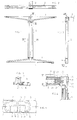
- the support construction represented in the drawing and in particular in the Figs. 1-3 thereof, comprises two feet 1, which are interconnected by means of the longitudinal beam 2.
- Each foot 1 is composed of an upper horizontal beam 3, a lower horizontal beam 4 and a post 5.
- the post 5 comprises a wall 6 with such a shape that two cavities 7 are formed, closed off in transverse direction, and three cavities 8, which are open sideways.
- cables or wires may be positioned, whereafter closing off of the cavities 8 may take place by means of the lid 9.
- the lid 9 consists of the plate 10 of which one of the longitudinal edges is shaped in such a manner that an edge section 11 is obtained, which may be properly positioned into a cavity 12 in the wall 6 of the post 5, while the plate 10 is further provided with a part 13 in an about square position thereto and shaped in such a manner that it may snap behind a part of a wall 14, limiting a cavity 8. In this way the lid 9 may be fixed on the post 5 in a simple but firm manner and can easily be removed therefrom again.
- the horizontal beams 3 and 4 will be manufactured as castings whereby the vertical parts 16 connect with the substantially horizontal part 15 thereof.
- the parts 16 have in cross-section a substantially square shape, such that when mounting the post 5 they may be received force fitted into the cavities 7 of the post which are indicated in Fig. 6. In this manner a very stable foot 1 is obtained.
- Fig. 4 shows the connection between the upper horizontal beam 3 and the longitudinal beam 2. It will be obvious that also the other end of the longitudinal beam 2 is connected with a foot 1 in the manner shown in Fig. 4. A working top 17 may then be positioned on the structure obtained.
- the cross-section of the longitudinal beam 2 is represented in Fig. 5.
- the profile is such, that a cable gutter 18 may be affixed thereon in a simple manner, to which purpose the cable gutter is provided with parts 19 and 20 which are about square to each other.
- the part 19 is inserted into a cavity, not specifically indicated, of the longitudinal beam 2 and the edge 20 snaps over an extending part, not further indicated, of the longitudinal beam 2.
- a cavity 21 is present in the longitudinal beam.
- an internal screw-thread has been applied at the end of the longitudinal beam 2, into which a sleeve 23 can be screwed which is provided with the internal screw-thread 24, for screwing therein a screw 25.
- the screw 25 extends further through a closing block 26, which closes the V-shaped groove 27, provided in the side wall 28 of the horizontal beam 3.
- a closing block 26 which closes the V-shaped groove 27, provided in the side wall 28 of the horizontal beam 3.
Landscapes
- Tables And Desks Characterized By Structural Shape (AREA)
- Details Of Indoor Wiring (AREA)
- Laminated Bodies (AREA)
- Bakery Products And Manufacturing Methods Therefor (AREA)
Priority Applications (1)
| Application Number | Priority Date | Filing Date | Title |
|---|---|---|---|
| AT86200033T ATE52012T1 (de) | 1985-08-13 | 1986-01-09 | Untergestell fuer schreibtisch oder tischplatte. |
Applications Claiming Priority (2)
| Application Number | Priority Date | Filing Date | Title |
|---|---|---|---|
| NL8502235 | 1985-08-13 | ||
| NL8502235A NL8502235A (nl) | 1985-08-13 | 1985-08-13 | Ondersteuningsconstructie voor bureau- of tafelblad. |
Publications (2)
| Publication Number | Publication Date |
|---|---|
| EP0212679A1 true EP0212679A1 (de) | 1987-03-04 |
| EP0212679B1 EP0212679B1 (de) | 1990-04-18 |
Family
ID=19846416
Family Applications (1)
| Application Number | Title | Priority Date | Filing Date |
|---|---|---|---|
| EP86200033A Expired - Lifetime EP0212679B1 (de) | 1985-08-13 | 1986-01-09 | Untergestell für Schreibtisch oder Tischplatte |
Country Status (7)
| Country | Link |
|---|---|
| US (1) | US4688748A (de) |
| EP (1) | EP0212679B1 (de) |
| JP (1) | JPS6241608A (de) |
| AT (1) | ATE52012T1 (de) |
| CA (1) | CA1278331C (de) |
| DE (1) | DE3670431D1 (de) |
| NL (1) | NL8502235A (de) |
Cited By (6)
| Publication number | Priority date | Publication date | Assignee | Title |
|---|---|---|---|---|
| GB2247613A (en) * | 1990-09-07 | 1992-03-11 | Martina Limited | A frame for a desk |
| EP0501000A1 (de) * | 1991-03-01 | 1992-09-02 | Walter Waibel | Höhenverstellbarer Tisch mit einer Linear- oder Geradführung |
| GB2266232A (en) * | 1992-04-23 | 1993-10-27 | Ashfield Eng Co | "A support device for a chair seat and armrests" |
| FR2725883A1 (fr) * | 1994-10-19 | 1996-04-26 | Narbur Sa | Pietement rigide pour bureau a plateau reversible |
| EP0736272A1 (de) * | 1995-04-06 | 1996-10-09 | Christmann & Pfeifer GmbH & Co. KG | Einrichtungssystem |
| US7463251B2 (en) | 2003-04-01 | 2008-12-09 | Tpo Displays Corp. | Display device having a sparkling effect and method for driving the same |
Families Citing this family (12)
| Publication number | Priority date | Publication date | Assignee | Title |
|---|---|---|---|---|
| US5289784A (en) * | 1991-03-01 | 1994-03-01 | Walter Waibel | Table base |
| US5195221A (en) * | 1991-04-26 | 1993-03-23 | Yoshida Kogyo K.K. | Slider with yoke for slide fastener and its joining method |
| JPH07275015A (ja) * | 1994-04-05 | 1995-10-24 | Ykk Kk | 自動停止機構付きスライドファスナー用スライダー |
| USD409419S (en) | 1997-07-30 | 1999-05-11 | Steelcase Inc. | Workstation |
| US6119989A (en) | 1997-12-29 | 2000-09-19 | Herman Miller, Inc. | Support assembly with a storable foot support |
| US6189268B1 (en) | 1999-06-04 | 2001-02-20 | Paoli, Inc. | Modular office furniture system |
| JP3935819B2 (ja) | 2002-10-29 | 2007-06-27 | Ykk株式会社 | 自動停止装置付スライドファスナー用スライダー |
| US20050189851A1 (en) * | 2004-02-27 | 2005-09-01 | Kirt Martin | Freestanding workstation |
| CN102018366B (zh) * | 2010-12-14 | 2012-05-09 | 高军 | 一种折叠式电脑桌 |
| ES2624302T3 (es) | 2011-03-31 | 2017-07-13 | Ykk Corporation | Cursor para cierre de cremallera con un dispositivo de retén automático y procedimiento para su fabricación |
| WO2018081415A1 (en) | 2016-10-27 | 2018-05-03 | Steelcase Inc. | Flip top table |
| USD932548S1 (en) * | 2019-01-23 | 2021-10-05 | P&P Imports LLC | Table game |
Citations (4)
| Publication number | Priority date | Publication date | Assignee | Title |
|---|---|---|---|---|
| US3559592A (en) * | 1968-02-07 | 1971-02-02 | Aurora Corp | Extensible typewriter stand |
| US3883202A (en) * | 1973-11-01 | 1975-05-13 | Voko Franz & Co | Desk having electrical supply lines which are laid in the table |
| FR2490941A1 (fr) * | 1980-09-29 | 1982-04-02 | Miller Ag Herman | Systeme de mobilier de bureau |
| EP0125869A2 (de) * | 1983-05-11 | 1984-11-21 | Mines And West Limited | Arbeitstisch, z.B. Schreibtisch |
Family Cites Families (3)
| Publication number | Priority date | Publication date | Assignee | Title |
|---|---|---|---|---|
| US3635174A (en) * | 1970-09-14 | 1972-01-18 | Massey Ferguson Ind Ltd | Desk with hidden wiring |
| US4117784A (en) * | 1971-09-14 | 1978-10-03 | Societa Anonima Castelli s.a.s. Di C. Castelli & C. | Disassemblable table |
| DE7831543U1 (de) * | 1978-10-23 | 1979-02-15 | Vario-Werke Dichmann Ag, 6233 Kelkheim | Seitengestell fuer bueromoebel |
-
1985
- 1985-08-13 NL NL8502235A patent/NL8502235A/nl not_active Application Discontinuation
-
1986
- 1986-01-09 EP EP86200033A patent/EP0212679B1/de not_active Expired - Lifetime
- 1986-01-09 DE DE8686200033T patent/DE3670431D1/de not_active Expired - Lifetime
- 1986-01-09 AT AT86200033T patent/ATE52012T1/de not_active IP Right Cessation
- 1986-02-18 JP JP61033683A patent/JPS6241608A/ja active Pending
- 1986-03-19 US US06/841,288 patent/US4688748A/en not_active Expired - Lifetime
- 1986-04-04 CA CA000505871A patent/CA1278331C/en not_active Expired - Fee Related
Patent Citations (4)
| Publication number | Priority date | Publication date | Assignee | Title |
|---|---|---|---|---|
| US3559592A (en) * | 1968-02-07 | 1971-02-02 | Aurora Corp | Extensible typewriter stand |
| US3883202A (en) * | 1973-11-01 | 1975-05-13 | Voko Franz & Co | Desk having electrical supply lines which are laid in the table |
| FR2490941A1 (fr) * | 1980-09-29 | 1982-04-02 | Miller Ag Herman | Systeme de mobilier de bureau |
| EP0125869A2 (de) * | 1983-05-11 | 1984-11-21 | Mines And West Limited | Arbeitstisch, z.B. Schreibtisch |
Cited By (8)
| Publication number | Priority date | Publication date | Assignee | Title |
|---|---|---|---|---|
| GB2247613A (en) * | 1990-09-07 | 1992-03-11 | Martina Limited | A frame for a desk |
| EP0501000A1 (de) * | 1991-03-01 | 1992-09-02 | Walter Waibel | Höhenverstellbarer Tisch mit einer Linear- oder Geradführung |
| GB2266232A (en) * | 1992-04-23 | 1993-10-27 | Ashfield Eng Co | "A support device for a chair seat and armrests" |
| GB2266232B (en) * | 1992-04-23 | 1995-11-15 | Ashfield Eng Co Wexford Ltd | A support device for a chair |
| FR2725883A1 (fr) * | 1994-10-19 | 1996-04-26 | Narbur Sa | Pietement rigide pour bureau a plateau reversible |
| WO1996012422A1 (fr) * | 1994-10-19 | 1996-05-02 | Narbur S.A. | Pietement rigide pour bureau a plateau reversible |
| EP0736272A1 (de) * | 1995-04-06 | 1996-10-09 | Christmann & Pfeifer GmbH & Co. KG | Einrichtungssystem |
| US7463251B2 (en) | 2003-04-01 | 2008-12-09 | Tpo Displays Corp. | Display device having a sparkling effect and method for driving the same |
Also Published As
| Publication number | Publication date |
|---|---|
| DE3670431D1 (de) | 1990-05-23 |
| JPS6241608A (ja) | 1987-02-23 |
| US4688748A (en) | 1987-08-25 |
| ATE52012T1 (de) | 1990-05-15 |
| NL8502235A (nl) | 1987-03-02 |
| CA1278331C (en) | 1990-12-27 |
| EP0212679B1 (de) | 1990-04-18 |
Similar Documents
| Publication | Publication Date | Title |
|---|---|---|
| US4688748A (en) | Support construction for desk- or table-top | |
| US4800695A (en) | Electrical raceway floor track | |
| US5715761A (en) | Article of furniture including a leg having wire management capabilities | |
| US4639049A (en) | Modular furniture | |
| US5994644A (en) | Modular furniture raceway component | |
| EP0458487A1 (de) | Raumunterteilungssystem mit Leitungsführungskanal | |
| US6557311B1 (en) | Retromolding extender | |
| CA2115787A1 (en) | Frame system for power and signal cable management | |
| US4257203A (en) | Under the wall wiring system with improved cover members | |
| EP0123972B1 (de) | Bausatzmöbelsystem | |
| GB2254966A (en) | Trunking assembly. | |
| US4577751A (en) | Retainer for soap dish | |
| EP0125869A2 (de) | Arbeitstisch, z.B. Schreibtisch | |
| JPH0247848Y2 (de) | ||
| USD478871S1 (en) | Electrical cable box | |
| CN213367331U (zh) | 一种多联保护螺丝孔位的电工底盒 | |
| KR0119952Y1 (ko) | 책상용 전선배선 덕트 | |
| JPH036122Y2 (de) | ||
| FR2751793B1 (fr) | Borne electrique femelle d'une seule piece | |
| JPH0214251Y2 (de) | ||
| GB2180276A (en) | A panel for partitioning a room | |
| JPS6138328Y2 (de) | ||
| JPS6347204Y2 (de) | ||
| JP3471481B2 (ja) | 間仕切り用パネルにおける幅木取付け構造 | |
| JPS6325845Y2 (de) |
Legal Events
| Date | Code | Title | Description |
|---|---|---|---|
| PUAI | Public reference made under article 153(3) epc to a published international application that has entered the european phase |
Free format text: ORIGINAL CODE: 0009012 |
|
| AK | Designated contracting states |
Kind code of ref document: A1 Designated state(s): AT BE CH DE FR GB IT LI LU NL SE |
|
| 17P | Request for examination filed |
Effective date: 19870515 |
|
| 17Q | First examination report despatched |
Effective date: 19880812 |
|
| GRAA | (expected) grant |
Free format text: ORIGINAL CODE: 0009210 |
|
| AK | Designated contracting states |
Kind code of ref document: B1 Designated state(s): AT BE CH DE FR GB IT LI LU NL SE |
|
| PG25 | Lapsed in a contracting state [announced via postgrant information from national office to epo] |
Ref country code: SE Effective date: 19900418 Ref country code: LI Effective date: 19900418 Ref country code: CH Effective date: 19900418 Ref country code: AT Effective date: 19900418 |
|
| REF | Corresponds to: |
Ref document number: 52012 Country of ref document: AT Date of ref document: 19900515 Kind code of ref document: T |
|
| REF | Corresponds to: |
Ref document number: 3670431 Country of ref document: DE Date of ref document: 19900523 |
|
| ITF | It: translation for a ep patent filed | ||
| REG | Reference to a national code |
Ref country code: CH Ref legal event code: PL |
|
| ET | Fr: translation filed | ||
| ITTA | It: last paid annual fee | ||
| PG25 | Lapsed in a contracting state [announced via postgrant information from national office to epo] |
Ref country code: LU Free format text: LAPSE BECAUSE OF NON-PAYMENT OF DUE FEES Effective date: 19910131 |
|
| PLBE | No opposition filed within time limit |
Free format text: ORIGINAL CODE: 0009261 |
|
| STAA | Information on the status of an ep patent application or granted ep patent |
Free format text: STATUS: NO OPPOSITION FILED WITHIN TIME LIMIT |
|
| 26N | No opposition filed | ||
| PGFP | Annual fee paid to national office [announced via postgrant information from national office to epo] |
Ref country code: BE Payment date: 19911210 Year of fee payment: 7 |
|
| PG25 | Lapsed in a contracting state [announced via postgrant information from national office to epo] |
Ref country code: BE Effective date: 19930131 |
|
| BERE | Be: lapsed |
Owner name: AHREND GROEP B.V. Effective date: 19930131 |
|
| REG | Reference to a national code |
Ref country code: GB Ref legal event code: IF02 |
|
| PG25 | Lapsed in a contracting state [announced via postgrant information from national office to epo] |
Ref country code: IT Free format text: LAPSE BECAUSE OF NON-PAYMENT OF DUE FEES Effective date: 20050109 |
|
| PGFP | Annual fee paid to national office [announced via postgrant information from national office to epo] |
Ref country code: GB Payment date: 20050112 Year of fee payment: 20 |
|
| PGFP | Annual fee paid to national office [announced via postgrant information from national office to epo] |
Ref country code: FR Payment date: 20050127 Year of fee payment: 20 |
|
| PGFP | Annual fee paid to national office [announced via postgrant information from national office to epo] |
Ref country code: DE Payment date: 20050331 Year of fee payment: 20 |
|
| PGFP | Annual fee paid to national office [announced via postgrant information from national office to epo] |
Ref country code: NL Payment date: 20050615 Year of fee payment: 20 |
|
| PG25 | Lapsed in a contracting state [announced via postgrant information from national office to epo] |
Ref country code: GB Free format text: LAPSE BECAUSE OF EXPIRATION OF PROTECTION Effective date: 20060108 |
|
| PG25 | Lapsed in a contracting state [announced via postgrant information from national office to epo] |
Ref country code: NL Free format text: LAPSE BECAUSE OF EXPIRATION OF PROTECTION Effective date: 20060109 |
|
| REG | Reference to a national code |
Ref country code: GB Ref legal event code: PE20 |
|
| NLV7 | Nl: ceased due to reaching the maximum lifetime of a patent |
Effective date: 20060109 |