EP0212724A2 - FVK-Blatt, insbesondere für einen Mehrblattpropeller mit Blattverstellung und einzeln abnehmbaren Blättern und Fertigungsverfahren - Google Patents
FVK-Blatt, insbesondere für einen Mehrblattpropeller mit Blattverstellung und einzeln abnehmbaren Blättern und Fertigungsverfahren Download PDFInfo
- Publication number
- EP0212724A2 EP0212724A2 EP86201325A EP86201325A EP0212724A2 EP 0212724 A2 EP0212724 A2 EP 0212724A2 EP 86201325 A EP86201325 A EP 86201325A EP 86201325 A EP86201325 A EP 86201325A EP 0212724 A2 EP0212724 A2 EP 0212724A2
- Authority
- EP
- European Patent Office
- Prior art keywords
- blade
- spar
- shell
- mold
- hull
- Prior art date
- Legal status (The legal status is an assumption and is not a legal conclusion. Google has not performed a legal analysis and makes no representation as to the accuracy of the status listed.)
- Granted
Links
- 238000004519 manufacturing process Methods 0.000 title claims description 11
- 239000002131 composite material Substances 0.000 title 1
- 239000004744 fabric Substances 0.000 claims abstract description 44
- 239000000835 fiber Substances 0.000 claims abstract description 22
- 229920005989 resin Polymers 0.000 claims abstract description 11
- 239000011347 resin Substances 0.000 claims abstract description 11
- 239000006260 foam Substances 0.000 claims abstract description 9
- 230000001413 cellular effect Effects 0.000 claims abstract description 8
- 229920003002 synthetic resin Polymers 0.000 claims description 21
- 239000000057 synthetic resin Substances 0.000 claims description 21
- 229910052751 metal Inorganic materials 0.000 claims description 12
- 239000002184 metal Substances 0.000 claims description 12
- 229920000049 Carbon (fiber) Polymers 0.000 claims description 11
- 239000004917 carbon fiber Substances 0.000 claims description 11
- 239000003365 glass fiber Substances 0.000 claims description 11
- VNWKTOKETHGBQD-UHFFFAOYSA-N methane Chemical compound C VNWKTOKETHGBQD-UHFFFAOYSA-N 0.000 claims description 10
- 229920000271 Kevlar® Polymers 0.000 claims description 8
- 239000004761 kevlar Substances 0.000 claims description 8
- 238000000034 method Methods 0.000 claims description 7
- 229920002994 synthetic fiber Polymers 0.000 claims description 7
- 229920001187 thermosetting polymer Polymers 0.000 claims description 7
- 230000002787 reinforcement Effects 0.000 claims description 5
- 230000000295 complement effect Effects 0.000 claims description 4
- 238000010438 heat treatment Methods 0.000 claims description 4
- 239000012783 reinforcing fiber Substances 0.000 claims description 4
- 230000007704 transition Effects 0.000 claims description 4
- 238000004026 adhesive bonding Methods 0.000 claims description 2
- 238000000151 deposition Methods 0.000 claims description 2
- 238000005470 impregnation Methods 0.000 claims description 2
- 238000009434 installation Methods 0.000 claims description 2
- 238000006116 polymerization reaction Methods 0.000 claims description 2
- 235000005921 Cynara humilis Nutrition 0.000 description 10
- 240000002228 Cynara humilis Species 0.000 description 10
- 235000008429 bread Nutrition 0.000 description 9
- 210000003462 vein Anatomy 0.000 description 7
- 208000031968 Cadaver Diseases 0.000 description 5
- 238000012423 maintenance Methods 0.000 description 5
- 238000005452 bending Methods 0.000 description 4
- 230000008901 benefit Effects 0.000 description 4
- 230000005540 biological transmission Effects 0.000 description 3
- 239000000463 material Substances 0.000 description 3
- 230000008569 process Effects 0.000 description 3
- 239000010935 stainless steel Substances 0.000 description 3
- 229910001220 stainless steel Inorganic materials 0.000 description 3
- 229910001200 Ferrotitanium Inorganic materials 0.000 description 2
- 241000940835 Pales Species 0.000 description 2
- 206010033546 Pallor Diseases 0.000 description 2
- 229920005830 Polyurethane Foam Polymers 0.000 description 2
- RTAQQCXQSZGOHL-UHFFFAOYSA-N Titanium Chemical compound [Ti] RTAQQCXQSZGOHL-UHFFFAOYSA-N 0.000 description 2
- 238000010276 construction Methods 0.000 description 2
- 238000005260 corrosion Methods 0.000 description 2
- 230000007797 corrosion Effects 0.000 description 2
- 230000000694 effects Effects 0.000 description 2
- 230000003628 erosive effect Effects 0.000 description 2
- 239000011496 polyurethane foam Substances 0.000 description 2
- 230000000717 retained effect Effects 0.000 description 2
- 239000007787 solid Substances 0.000 description 2
- 239000010936 titanium Substances 0.000 description 2
- 229910000838 Al alloy Inorganic materials 0.000 description 1
- 241000195940 Bryophyta Species 0.000 description 1
- OKTJSMMVPCPJKN-UHFFFAOYSA-N Carbon Chemical compound [C] OKTJSMMVPCPJKN-UHFFFAOYSA-N 0.000 description 1
- 229910000831 Steel Inorganic materials 0.000 description 1
- 238000005299 abrasion Methods 0.000 description 1
- 239000000853 adhesive Substances 0.000 description 1
- 230000001070 adhesive effect Effects 0.000 description 1
- 238000004378 air conditioning Methods 0.000 description 1
- 238000002048 anodisation reaction Methods 0.000 description 1
- 238000007743 anodising Methods 0.000 description 1
- 230000000712 assembly Effects 0.000 description 1
- 238000000429 assembly Methods 0.000 description 1
- 230000008859 change Effects 0.000 description 1
- 239000011248 coating agent Substances 0.000 description 1
- 238000000576 coating method Methods 0.000 description 1
- 238000001816 cooling Methods 0.000 description 1
- 230000003247 decreasing effect Effects 0.000 description 1
- 230000006866 deterioration Effects 0.000 description 1
- 238000006073 displacement reaction Methods 0.000 description 1
- 238000009826 distribution Methods 0.000 description 1
- 230000009977 dual effect Effects 0.000 description 1
- 239000000428 dust Substances 0.000 description 1
- 230000007613 environmental effect Effects 0.000 description 1
- 230000002349 favourable effect Effects 0.000 description 1
- 239000011152 fibreglass Substances 0.000 description 1
- 239000011521 glass Substances 0.000 description 1
- 229910002804 graphite Inorganic materials 0.000 description 1
- 239000010439 graphite Substances 0.000 description 1
- 230000010354 integration Effects 0.000 description 1
- 239000000314 lubricant Substances 0.000 description 1
- 238000003754 machining Methods 0.000 description 1
- 239000002991 molded plastic Substances 0.000 description 1
- 235000011929 mousse Nutrition 0.000 description 1
- 210000000056 organ Anatomy 0.000 description 1
- 238000007747 plating Methods 0.000 description 1
- 230000000379 polymerizing effect Effects 0.000 description 1
- 230000036316 preload Effects 0.000 description 1
- 230000002829 reductive effect Effects 0.000 description 1
- 230000003014 reinforcing effect Effects 0.000 description 1
- 230000008439 repair process Effects 0.000 description 1
- 230000000284 resting effect Effects 0.000 description 1
- 239000010959 steel Substances 0.000 description 1
Images
Classifications
-
- B—PERFORMING OPERATIONS; TRANSPORTING
- B29—WORKING OF PLASTICS; WORKING OF SUBSTANCES IN A PLASTIC STATE IN GENERAL
- B29D—PRODUCING PARTICULAR ARTICLES FROM PLASTICS OR FROM SUBSTANCES IN A PLASTIC STATE
- B29D99/00—Subject matter not provided for in other groups of this subclass
- B29D99/0025—Producing blades or the like, e.g. blades for turbines, propellers, or wings
-
- B—PERFORMING OPERATIONS; TRANSPORTING
- B64—AIRCRAFT; AVIATION; COSMONAUTICS
- B64C—AEROPLANES; HELICOPTERS
- B64C11/00—Propellers, e.g. of ducted type; Features common to propellers and rotors for rotorcraft
- B64C11/16—Blades
- B64C11/20—Constructional features
- B64C11/26—Fabricated blades
-
- B—PERFORMING OPERATIONS; TRANSPORTING
- B64—AIRCRAFT; AVIATION; COSMONAUTICS
- B64C—AEROPLANES; HELICOPTERS
- B64C27/00—Rotorcraft; Rotors peculiar thereto
- B64C27/32—Rotors
- B64C27/46—Blades
- B64C27/473—Constructional features
-
- B—PERFORMING OPERATIONS; TRANSPORTING
- B64—AIRCRAFT; AVIATION; COSMONAUTICS
- B64C—AEROPLANES; HELICOPTERS
- B64C27/00—Rotorcraft; Rotors peculiar thereto
- B64C27/82—Rotorcraft; Rotors peculiar thereto characterised by the provision of an auxiliary rotor or fluid-jet device for counter-balancing lifting rotor torque or changing direction of rotorcraft
-
- F—MECHANICAL ENGINEERING; LIGHTING; HEATING; WEAPONS; BLASTING
- F01—MACHINES OR ENGINES IN GENERAL; ENGINE PLANTS IN GENERAL; STEAM ENGINES
- F01D—NON-POSITIVE DISPLACEMENT MACHINES OR ENGINES, e.g. STEAM TURBINES
- F01D5/00—Blades; Blade-carrying members; Heating, heat-insulating, cooling or antivibration means on the blades or the members
- F01D5/12—Blades
- F01D5/28—Selecting particular materials; Particular measures relating thereto; Measures against erosion or corrosion
- F01D5/282—Selecting composite materials, e.g. blades with reinforcing filaments
-
- B—PERFORMING OPERATIONS; TRANSPORTING
- B64—AIRCRAFT; AVIATION; COSMONAUTICS
- B64C—AEROPLANES; HELICOPTERS
- B64C27/00—Rotorcraft; Rotors peculiar thereto
- B64C27/32—Rotors
- B64C27/46—Blades
- B64C27/473—Constructional features
- B64C2027/4733—Rotor blades substantially made from particular materials
- B64C2027/4736—Rotor blades substantially made from particular materials from composite materials
-
- B—PERFORMING OPERATIONS; TRANSPORTING
- B64—AIRCRAFT; AVIATION; COSMONAUTICS
- B64C—AEROPLANES; HELICOPTERS
- B64C27/00—Rotorcraft; Rotors peculiar thereto
- B64C27/82—Rotorcraft; Rotors peculiar thereto characterised by the provision of an auxiliary rotor or fluid-jet device for counter-balancing lifting rotor torque or changing direction of rotorcraft
- B64C2027/8254—Shrouded tail rotors, e.g. "Fenestron" fans
-
- F—MECHANICAL ENGINEERING; LIGHTING; HEATING; WEAPONS; BLASTING
- F05—INDEXING SCHEMES RELATING TO ENGINES OR PUMPS IN VARIOUS SUBCLASSES OF CLASSES F01-F04
- F05D—INDEXING SCHEME FOR ASPECTS RELATING TO NON-POSITIVE-DISPLACEMENT MACHINES OR ENGINES, GAS-TURBINES OR JET-PROPULSION PLANTS
- F05D2200/00—Mathematical features
- F05D2200/30—Mathematical features miscellaneous
- F05D2200/31—Mathematical features miscellaneous odd
-
- Y—GENERAL TAGGING OF NEW TECHNOLOGICAL DEVELOPMENTS; GENERAL TAGGING OF CROSS-SECTIONAL TECHNOLOGIES SPANNING OVER SEVERAL SECTIONS OF THE IPC; TECHNICAL SUBJECTS COVERED BY FORMER USPC CROSS-REFERENCE ART COLLECTIONS [XRACs] AND DIGESTS
- Y02—TECHNOLOGIES OR APPLICATIONS FOR MITIGATION OR ADAPTATION AGAINST CLIMATE CHANGE
- Y02T—CLIMATE CHANGE MITIGATION TECHNOLOGIES RELATED TO TRANSPORTATION
- Y02T50/00—Aeronautics or air transport
- Y02T50/60—Efficient propulsion technologies, e.g. for aircraft
-
- Y—GENERAL TAGGING OF NEW TECHNOLOGICAL DEVELOPMENTS; GENERAL TAGGING OF CROSS-SECTIONAL TECHNOLOGIES SPANNING OVER SEVERAL SECTIONS OF THE IPC; TECHNICAL SUBJECTS COVERED BY FORMER USPC CROSS-REFERENCE ART COLLECTIONS [XRACs] AND DIGESTS
- Y10—TECHNICAL SUBJECTS COVERED BY FORMER USPC
- Y10T—TECHNICAL SUBJECTS COVERED BY FORMER US CLASSIFICATION
- Y10T156/00—Adhesive bonding and miscellaneous chemical manufacture
- Y10T156/10—Methods of surface bonding and/or assembly therefor
- Y10T156/1002—Methods of surface bonding and/or assembly therefor with permanent bending or reshaping or surface deformation of self sustaining lamina
- Y10T156/1028—Methods of surface bonding and/or assembly therefor with permanent bending or reshaping or surface deformation of self sustaining lamina by bending, drawing or stretch forming sheet to assume shape of configured lamina while in contact therewith
- Y10T156/103—Encasing or enveloping the configured lamina
-
- Y—GENERAL TAGGING OF NEW TECHNOLOGICAL DEVELOPMENTS; GENERAL TAGGING OF CROSS-SECTIONAL TECHNOLOGIES SPANNING OVER SEVERAL SECTIONS OF THE IPC; TECHNICAL SUBJECTS COVERED BY FORMER USPC CROSS-REFERENCE ART COLLECTIONS [XRACs] AND DIGESTS
- Y10—TECHNICAL SUBJECTS COVERED BY FORMER USPC
- Y10T—TECHNICAL SUBJECTS COVERED BY FORMER US CLASSIFICATION
- Y10T156/00—Adhesive bonding and miscellaneous chemical manufacture
- Y10T156/10—Methods of surface bonding and/or assembly therefor
- Y10T156/1002—Methods of surface bonding and/or assembly therefor with permanent bending or reshaping or surface deformation of self sustaining lamina
- Y10T156/1043—Subsequent to assembly
Definitions
- the present invention relates to a blade and to a method of manufacturing this blade, which is particularly intended for equipping a multi-blade propeller.
- Multipale propellers with variable pitch usable as tail rotors of the faired type for helicopters are described in French patent 1,593,008 and in French patent application No. 2,430,354 in the name of the Applicant.
- each of the blades of the multi-blade propeller is connected by an elongated radial element, twistable about its longitudinal axis, to a hub driven in rotation by a rotor shaft around the axis of the propeller, and an interlocking of the foot of each blade in the hub allows both the rotation of the blade around its longitudinal axis and a slight angular movement of the blade in flap and in drag, while, for the control of the incidence, the foot of each blade comprises a crankpin connected, by a ball joint, to a plate perpendicular to the axis of the propeller and axially movable.
- Such a propeller mounted as a rear rotor, compensating for the driving torque of a helicopter, in a window or vein delimited vertically in the rear part of the fuselage or in the vertical tail of the helicopter by a fairing, is very advantageous insofar as it provides great safety when the helicopter is evolving close to the ground, and because of the fairing inside which the propeller rotates, the blades of the latter are subjected to lower stresses than those of a conventional tail rotor, not faired, which increases their lifespan.
- such a multi-blade propeller has a number of drawbacks.
- its blades are made of light metal. They are therefore subject to corrosion, erosion, and fatigue due to alternating stresses.
- the machining of the blades is long and delicate and therefore costly, all the more so since not only the solid part of the blade subjected to aerodynamic forces must be produced with a profile and a precise twisting law, exactly reproducible from one blade to another, while being protected at the leading edge by the use of a surface hardening process such as hard anodization, but that the blade root is also delicate and costly to achieve.
- the blade root comprises on the one hand, a hollow intermediate part, in which an axial recess is machined intended to receive the external radial end equipped with a sleeve, of the elongated element connecting the blade to the hub, and a transverse bore opening into the axial recess and intended to receive an axis passing through the bush and ensuring the attachment of the blade root to the elongated element, and on the other hand, a cylindrical end bearing, the outer surface is superficially hardened by chromium-plating or anodizing and the central part of which is thinned, and which is intended to allow the rotation of the blade, around its longitudinal axis, for controlling the pitch.
- such a blade is a member whose manufacturing and maintenance cost is relatively high.
- two diametrically opposite blades consist essentially on the one hand of a common spar, produced by a single elongated blade made of fibers a high mechanical resistance agglomerated by a synthetic resin, the blade being subject by its middle to a hub and, on the other hand, by two shells with aerodynamic profile fixed to the blade on either side of the hub, the inner end of each shell being integral with a member for controlling the incidence of the corresponding blade, which is arranged so as to exert on the shell a torsional torque centered on the longitudinal axis of the elongated blade.
- the latter is formed by two flat bundles of fibers, which are arranged so as to provide an opening in the middle of the blade allowing the free passage of a collective control axis of the incidence of all the blades, this axis being, as this is the case in the embodiment described in French patent 1,593,008, mounted to slide axially in the shaft of the rotor which is tubular.
- the shell of each blade is joined over its entire length to the corresponding part of the blade by a mass of cellular or foam adhesive synthetic material, of low density and possibly having a certain residual elasticity.
- Each shell is essentially formed by layers of glass fiber fabrics and by a leading edge made of stainless steel sheet, the whole being agglomerated by a synthetic resin polymerized so as to integrate the leading edge into the layers. of fabrics.
- the incidence control member is constituted by a molded plastic sleeve loaded with glass fibers and which is secured to the foot of each blade.
- a bearing surface constituted by a metallic circular ring, is embedded in or glued to the internal cylindrical end of the sleeve, coaxial with the longitudinal axis of the blade, and a metallic pitch control finger is embedded in a lateral arm carried by the inner end of the sleeve.
- the end of the axis of collective control of L'incidence des pays, which passes through the hub, carries a plate substantially perpendicular to this axis and to which are fixed pairs of lugs provided with holes intended for the engagement of the control fingers sleeves of two neighboring blades.
- This embodiment has the advantages that the structure of the incidence control device is very simple, and that each blade is also of a simple, robust and light structure, practically insensitive to the phenomena of erosion and to the "effect of 'nicks', so their lifespan is virtually unlimited.
- the multi-blade propeller thus produced has a much lower cost price and is much lighter than propellers with metal blades, and its maintenance costs are much lower.
- the propeller hub is formed by a glued stack comprising, in superposition, the middle parts of all the elongated blades as well as two outer layers of glass fiber fabrics impregnated with a polymerized synthetic resin, the whole of the stack being embedded in a synthetic filling material, and the hub thus formed being fixed to the tubular drive shaft of the rotor by pairs of bolts which pass through the periphery of the glued stack, and on the other side of the middle part of each elongated blade.
- this embodiment must necessarily include an even number of blades, since the latter are secured two by two by common beams, which is disadvantageous, since the multi-blade propellers used as a faired-type tail rotor have a lower noise level when they have an odd number of blades.
- a blade intended for equipping a multi-blade propeller, and in particular a propeller usable as the rear rotor of a rotorcraft, is also described in the patents of the United States of America Nos. 3,647,317 and 4,306,837 .
- the first of these two patents describes an impeller of axial flow, for cooling towers and heat exchangers in general, and this propeller is equipped with glass fiber blades.
- Each blade is essentially made up of a profiled shell made of glass fiber fabrics filled with high density polyurethane foam and in which is placed a steel spar having an H section and embedded in the filling foam to which the spar is chemically linked.
- the advantage of such a blade is that its fiberglass skin offers exceptional resistance to corrosion and abrasion under severe environmental conditions.
- the high density polyurethane foam strengthens the profile over the entire span and efficiently transfers the loads applied to the skin to the spar, increasing the torsional stability and the impact resistance of the blade.
- this blade has a major drawback, linked to the nature and shape of its spar, which is costly and bulky, so that this solution cannot be used to make blades of small thickness and reduced weight.
- each blade has a skin surrounding a honeycomb filling body preformed, the spar being constituted by a thin and flat strip of unidirectional fibers with high mechanical resistance, for example of Kevlar glass or graphite, common to the two opposite blades and extending over their entire span, and which has a middle part relatively thick, forming the hub, to which are adjacent two thinner, flexible and flexible parts, each of which is extended by two end parts, each divided into two half-beams, one of which is a half-beam of the upper surface and the other of which is a half lower side member each extending just under the part of the corresponding skin of the blade, between this skin and the filling body.
- the spar being constituted by a thin and flat strip of unidirectional fibers with high mechanical resistance, for example of Kevlar glass or graphite, common to the two opposite blades and extending over their entire span, and which has a middle part relatively thick, forming the hub, to which are adjacent two thinner, flexible and flexible parts, each of which is extended by two end
- the major drawback resides in the structure of the spar, common to the two opposite blades and in the form of an elongated and lying H, therefore of complex and costly construction.
- this assembled structure consisting of the shell, the filling body and the spar, lies in the direct connection of one face of the spar, over the entire length of the latter which is included in the shell, with the covering fabrics.
- of the upper surface which provides a connection between the spar and the coating of better quality by direct bonding of an element on the other by a large surface, which results in better resistance to centrifugal force, bending moments and torque.
- the shell is formed by a stack, from the outside towards the inside, of at least one layer of glass fiber or Kevlar fabrics, but preferably two layers which are crossed and inclined at 45 ° on the longitudinal axis of the blade, and at least one layer of carbon fiber fabrics, but preferably two layers also crossed and inclined in a similar manner .
- the junction, at the trailing edge, of the upper and lower surfaces forming the shell is reinforced by an internal stirrup made of carbon fiber fabrics, bonded by its external faces to the internal faces of the tissues of the shell.
- the root portion of the spar arranged in a loop surrounded by a coil for attaching the blade by its end opposite to the portion of spar fixed in the hull.
- the elongated blade forming the longero.n is constituted by a single bundle of rovings which is folded back on itself in two equal halves whose internal parts close to the folding zone, constitute the part d 'root of the spar and the external parts of which, distant from the folding zone, are joined to one another and constitute the part of the spar received in the hull.
- the foot of the blade which is crossed by the root portion of the spar, is preferably made with extensions of the layer or layers of fiber fabrics constituting the shell and covering a stack of layers of fabric of reinforcing fibers.
- This blade root is for example constituted by a hollow cylinder connected by its outer end to the current part of the blade by a transition zone and whose inner end has a frustoconical shape, which facilitates the connection of the blade by his foot to an incidence control member coming to cap the blade root.
- the invention also relates to a method of manufacturing such a blade, by means of a lower half-mold and an upper half-mold, the complementary impressions of which respectively have the shape of the lower surface and the upper surface of the blade.
- the method according to the invention consisting in depositing in the lower half-mold a flap of at least one layer of fabrics of fibers with high mechanical resistance, impregnated with a polymerizable synthetic resin and intended to form the lower surface part of the blade shell, is characterized in that it further consists in placing, over this or these layers of tissue, a filling body preformed from a cellular synthetic material or from foam having, along its entire length, a cutout which opens in the face of the body facing the upper surface, to cover the rear edge of this filling body with a stirrup preformed in carbon-free fabrics, to be placed in the cutout a part intended to be fixed in the hull of a single elongated blade of rovings of fibers with high mechanical resistance agglomerated by a synthetic polymerizable resin and intended to constitute the spar of the blade, and of which an end part , intended to form a root portion of the spar, is disposed beyond a corresponding end of the filling body, to have on the assembly thus formed in the lower
- the method according to the invention consists in using a single thermosetting synthetic resin to impregnate the flaps of each of the layers of fiber fabrics of the shell and of the trailing edge stirrup and to agglomerate the rovings of the single elongated blade of the spar, respectively after having cut each layer in the form of an elongated layer comprising two adjacent flaps on either side of a longitudinal median axis corresponding to the leading edge of the hull and intended to respectively form the part d '' lower surface and the upper surface part of the hull, and after having spread a single bundle of rovings folded back on itself in two equal halves, in order to form the single blade of the spar, and the pro assigned according to the invention also consists in leaving the shutter of the upper surface part of each layer outside the
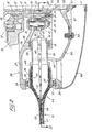
- the multi-blade rotor used as an anti-torque rear rotor, compensating for the engine torque transmitted to at least one main rotor by a main gearbox, and generally designated by 1,. is mounted and rotated in a vertical vein or window 2, of slightly frustoconical shape, delimited in the rear part of the fuselage or tail 3 of a helicopter by a fairing 4.
- the rotor 1 is supported and driven by an auxiliary gearbox 5 housed in a double-walled casing, of generally cylindrical shape, held in the center of the stream 2 by a support comprising several faired radial arms 6.
- the auxiliary gearbox 5 which is for example such as that described and shown in French patent 1,593,008. to which one will advantageously refer for more details, contains a bevel gear, the primary pinion of which is driven by a drive shaft 7 connecting the main gearbox to the auxiliary gearbox 5, and passing through a hollow arm 8_binding the fairing 4 to the casing of the auxiliary transmission box 5.
- the latter also contains a bevel gear 9, urged by a rod for collective control of the incidence 10 in order to move a collective control shaft parallel to the axis of the vein 2 incidence described below.
- the angular gear 9 and the connecting rod 10 have been shown diagrammatically as in FIG. 1 of the aforementioned patent, for the sake of clarity, but the connecting rod 10 may possibly also pass through the hollow arm 8.
- the rotor 1 comprises a tubular central shaft 11 coaxial with the vein 2, and mounted in rotation around the axis A of the vein 2 by bearings housed in the auxiliary transmission box 5.
- L shaft 11 is rotated by axial splines 12 of a shaft portion passing through the casing 13 of the auxiliary gearbox 5, and which are engaged with corresponding splines of the secondary bevel gear 14 of the bevel gear housed in the auxiliary gearbox 5, this secondary pinion 14 being itself rotatably mounted in the casing 13 by a roller bearing 15.
- the shaft 11 By its grooves 12 the shaft 11 is also engaged with corresponding grooves of the internal axial end (that is to say facing the auxiliary gearbox 5) of a drive sleeve 17 which is in axial support by this internal axial end against a seal carrier 16, tightened against the secondary pinion 14.
- This sleeve 17, integral in rotation with the shaft 11, is coaxial with the latter thanks to two internal cylindrical bearing surfaces 18 and 19 offset axially and such that the external threaded axial end 20 of the shaft 11 is projecting by relative to the external axial cylindrical bearing surface 19 of the sleeve 17.
- this sleeve 17 has an external radial annular flange 21, by which the sleeve 17 is fixed to a hub described below and to which the sleeve 17 transmits the engine torque received from the shaft 11, which receives it from the bevel gear 14, and the sleeve 17 resumes also part of the thrust forces developed by the rotation of the blades described below.
- the sleeve 17 is held axially in place, by exerting a predetermined axial bearing force against the seal carrier 16, by a threaded ring 22, screwed onto the threaded end 20 of the shaft 11, and which is crossed by four axial bores regularly distributed over the ring 22 and in each of which is screwed a setting screw 23 whose end of the rod, in the form of a support stud 24, is applied against a support surface of the bottom of a notch 25 formed in the external axial end face of the sleeve 17.
- the hub is substantially in the form of a circular cake pan with a central chimney. More specifically, the hub comprises a hub body 26, of pressed sheet metal or of an injected and optionally reinforced synthetic material, having the shape of a cup, the bottom of which consists of a planar external radial part 27 connected by an intermediate part.
- the hub body 26 also consists of two cylindrical walls coaxial with one another, one of which 30 in an external radial position and is connected by its internal axial end to the external radial end of the bottom part 27 is of a height greater than that of the other cylindrical wall 31, in the internal radial position and is connected by its internal axial end to the frustoconical part 28 of the bottom.
- these two walls 30 and 31 are pierced, for each of the blades which the rotor must include, two circular openings 32 and 33 coaxial centered on a radial axis, and such that the opening 32 in the external wall 30 is of a diameter greater than the diameter of the opening 33 in the internal wall 31.
- Two self-lubricating rings 34 and 35 are housed respectively in annular grooves formed in the wall of the openings 32 and 33, the internal diameter of the ring 34 being greater than that of the ring 35.
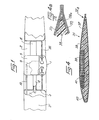
- the rotor also comprises eleven blades 36 each having substantially 40 cm in length, 7.7 cm in width and a twist law of approximately 7 °, and the structure of these blades 36 is described below with reference not only to the figures. 2 and 3 but also in Figures 4 and 4a.
- Each blade 36 consists essentially of, in its main part, of a hull 37 having the shape of the desired aerodynamic profile, of a filling bread preform 3 8, a bracket trailing edge 72, a beam 39 and a leading edge cap made of titanium or stainless steel 40.
- the shell 37 is produced by a stack made up, from the outside towards the inside, of two superimposed layers of glass fiber or Kevlar (registered trademark) fabrics arranged so that, for example, their son of chain are crossed at right angles and inclined at 45 ° on the longitudinal axis of the blade, and two layers of carbon fiber fabrics, preferably also crossed and inclined at 45 °, and all of these four layers are agglomerated by a synthetic resin polymerized by thermosetting so as to form a hollow box ensuring the torsional rigidity of the entire blade, in which the filling bar 38 does not have any shear strength.
- Kevlar registered trademark
- This filling bar 38 is an element of foam or cellular synthetic material, whose external shape corresponds to the internal volume of the shell 37 in which it is enclosed, and which has a cutout 41 of substantially rectangular section extending over its entire length and opening in the face of the bread 38 which faces the upper surface of the blade 36.
- This stirrup 72 is bonded by its external faces to the fabrics constituting the shell 37 of the blade and by its internal faces, to the filling bar 38.
- This stirrup 72 is essentially intended to ensure the holding of the shell 37 to the torsional cut and to the moments of drag requesting it.
- the spar 39 is an elongated solid blade made of Kevlar rovings agglomerated by a thermoset synthetic resin and having, on about two thirds of its length which are received in the current part of the blade 36, a section which corresponds to that of the housing delimited by the cut 41 of the filling bread 38 and by the underside of the part facing the upper surface of the shell 37.
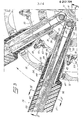
- the spar 39 intended to take up the centrifugal forces urging the blade 36 in service constitutes, by its third third which leaves the current part of the blade by crossing the blade root described below, a root portion 42 in the form of loop (see Figure 3) and increasing thickness (see Figure 2) of the part of the spar 39 received in the current part of the blade 36 towards the free end of the loop, which surrounds a metal coil 43 forming the fastener of the blade 36, by being wound in a groove around this coil 43.
- the particularity of the assembly of the shell 37, the filling bar 38 and the spar 39 lies in the direct connection of the face of the spar 39 which is not opposite the one of the faces of the cutout 41 of the filling roll 38 with the inner face of the inner layer of the covering fabrics of the upper surface part of the shell 37, over the entire length of the spar 39 which is received in the current part of the blade 36, that is to say over the outer two thirds of the length of the beam 39.
- This structural feature of the blade 36 has the dual advantage of providing an excellent quality connection between the spar 39 and the hull 37 by direct bonding of one element on the other over a large area, which generates better resistance to centrifugal force, to bending moments and to torsional torque which act on the blade, and to facilitate the manufacture of the blade 36 according to a process which will be described later.
- Each blade 36 further comprises a blade root 44, produced with the layers of fiber fabrics of the covering or of the shell 37 and with layers of fabric of reinforcing fibers 45, in order to give the blade root 44 a sufficient thickness.
- This blade root 44 comprises a hollow cylinder 46, the internal radial end of which tapers into a truncated cone, and which is connected by its external radial end to the current part of the blade 36 by a transition zone 47 extending along a length close to the blade of the blade 36.
- the blade root 44 is mounted by its hollow cylinder 46 in a bearing constituted by a metal sleeve 48 made of aluminum alloy.
- This sleeve 48 comprises two tubular parts 49 and 50 coaxial, of circular section having different internal and external diameters, and whose cylindrical bores are connected by a frustoconical part.
- the hollow cylinder 46 of the blade root 44 and its frustoconical internal radial end are respectively capped by the tubular part of larger internal and external diameter 49 and by the frustoconical part of the sleeve 48, and are fixed respectively to these two parts by gluing.
- This shape of the sleeve 48 promotes the support of the latter against the hollow cylinder 46 of the blade root 44 under the effect of centrifugal force.
- the part with the smallest internal and external diameter 50 of the sleeve 48 has a collar 52 of spheroid shape, the maximum external diameter of which corresponds to the internal diameter of the self-supporting ring.
- lubricant 35 housed in the opening 33 of the inner wall 31 of the hub 26. From similarly, a collar 51, also.
- the latter also comprises a lateral boss 53, attached to the frustoconical part of the sleeve 48, between the two flanges 51 and 52, and extending in a direction substantially perpendicular to the axis of the sleeve 48 as well as to the axis A rotor rotation.
- the dimensions and size of the sleeve 48 and its lateral boss 53 are such that by suitably tilting a blade 36 and its sleeve 48 after having introduced the internal radial end of the loop of the root portion 42 and the coil metallic 43 as well as the part 50 of the sleeve 48 in an opening 32 of the external wall 30 of the hub, it is possible to pass the lateral boss 53 in this opening 32, then to engage the part 50 of the sleeve 48 in the corresponding opening 33 and position the parts 49 and 50 so that the flanges 51 and 52 come respectively to bear inside the rings 34 and 35 of the openings 32 and 33.
- the boss 53 is opposite one of several axial lugs 54, in number equal to the number of blades 36 of the rotor, and the external axial end of which is secured to a control plate 55 annular and domed.
- a crown of screw-nut assemblies 56 the internal radial edge of the control plate 55 is superimposed and secured to the external radial edge of a flange 57 of frustoconical shape, in order to have excellent rigidity, and which is mounted by fitting tapered from its central part on a tapered spindle 58 of a collective pitch control shaft 59 slidably mounted axially in the tubular rotor shaft 11, the flange 57 being retained on the actuator of pitch 59 by a support flange nut 60 screwed onto the threaded external axial end of the spindle 58.
- Each of the axial tabs 54 of the plate 55 is pierced with a bore equipped with a ring 61 in which is received a ball joint 62 retained by a transverse pin on the rod and against the head of a head stud 63, the threaded end of the rod passes through a bore in the boss 53 and receives a nut 64 pinned on the rod in the screwed position.
- Each boss 53 constitutes, with the stud 63, nut 64, the ball joint 62 and the tab 54 which correspond to it, a lever for controlling the pitch of the blade 36, the foot 44 of which is integral with the corresponding sleeve 48.
- the different pitch control levers thus formed, the control plate 55, the flange 57 and the collective pitch control shaft 59 constitute a collective control assembly for the pitch of the blades 36 of the rotor, such that any axial displacement of the 'shaft 59 in the tubular shaft 11 controls, via the pitch control levers, the application of a torque on the sleeves 48, and therefore also on the blade feet 44 and the blades 36 around longitudinal axes of the latter.
- Each pitch control lever is located between the two flanges 51 and 52 of the corresponding bearing sleeve, which are spaced apart as much as possible from each other, which allows better support for each blade 36 and reduces the radial forces exerted by the flanges 51 and 52 on the corresponding self-lubricating rings 34 and 35.
- a domed cover 69 fixed, for example by screws, by its external radial edge on the periphery of the external radial wall 30 of the hub body 26, covers the collective pitch control assembly of the blades 36 and protects the hub against the ingress of dust, stones, etc.
- the central part 29 of the hub body 26 works little and only serves for the transmission of the engine torque from the drive sleeve 17 to the blades 36, in order to rotate the latter.
- the hub body 26 takes up part of the bending forces. This is obtained thanks to the favorable arrangement of the support flanges 51 and 52 of the bearing sleeves 48.
- the rings 65 and 66 for distributing the centrifugal forces avoid any significant stress on the drive sleeve 17 and prevent working. the fixing studs 67 in bending.
- This embodiment allows easy assembly and disassembly of the various components of the multi-blade rotor, which considerably facilitates maintenance operations and reduces the cost of maintenance.
- it is easy to change a damaged blade 36 without having to dismantle other elements, since it suffices to decouple the corresponding boss 53 from the stud 63 by unscrewing the nut 64 and uncoupling the coil 43 corresponding to the stud 67 by unscrewing the nut 68.
- the flange 57 can be perforated to allow access to the nut 68 without having to dismantle the flange 57 (and the plate 55 of the shaft 59, after removing the bosses 53 from all the blades 36.
- a method of manufacturing a blade such as 36 the structure of which has been described with reference to Figures 2 to 4, and which is intended not only for the equipment of a multi-blade propeller such as that described above and used as the rear rotor of a helicopter, but also for equipping fans or blowers, in particular for blowers and air conditioning or gaseous heat exchange devices.
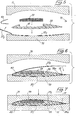
- This process is implemented using two complementary half-molds, one of which 70 below has an internal imprint whose shape corresponds transversely and longitudinally to the shape of the lower surface of the blade 36, and the other of which 71 upper has an internal imprint whose shape corresponds under the same conditions to that of the upper surface of the blade.
- two elongated layers of glass fiber or Kevlar fabrics are cut, then two elongated layers of carbon fiber fabrics, each layer comprising two adjacent flaps 37 I and 37 E, on either side of a longitudinal median axis corresponding to the leading edge of the shell 37 and intended respectively to form the lower surface part and the upper surface part of the shell 37.
- These fabric layers are pre-impregnated with a synthetic resin which can be polymerized by thermosetting example.
- the flaps 37 1 of the two layers of glass fiber or Kevlar fabric layers are then deposited in the imprint of the lower half-mold 70, leaving the flaps 37 E of these two layers outside the lower half-mold 70, on the leading edge side, then the two layers of carbon fiber fabrics are deposited in the same way on these two layers, so that all the flaps 37 1 of the four layers of fiber fabrics forming the shell 37 are stacked in the lower half-mold 70, as shown in FIG. 5. Then placed on this stack of flaps 37 1 the preformed bread 38 of cellular material or filling foam, the cut 41 opens up. The manufacture of this loaf 38 in the suitable shape in a second mold fitted for this purpose poses no difficulty and does not deserve further explanation.
- the reinforcement stirrup 72 consisting of carbon fiber fabrics prepreg of synthetic resin and preformed in V in a separate tool. Then, in the cutout 41 of the preformed bread 38 and in position in the lower half-mold 70, the spar 39 is formed, consisting of an elongated blade, one end portion of which is shaped as a loop.
- blades of this kind intended in particular to constitute the webs of rotorcraft rotor blades is well known, so that it is not necessary to describe it in detail; suffice it to say that blades of this kind can be formed not only with rovings in Kevlar fibers, but also with rovings in glass fibers or in carbon fibers. All these rovings can be agglomerated for example by impregnating the bundle they form with a polymerizable resin, in particular thermosetting.
- This known method makes it possible in particular to produce thin and relatively narrow elongated blades which have mechanical properties which are particularly advantageous for producing the webs of the blades of rotorcraft rotors: they indeed combine great mechanical resistance in the longitudinal direction, allowing them to '' absorb the centrifugal forces applied to the blades of which they constitute the longitudinal members, without excessive stress or fatigue, with relative flexibility, in particular in torsion around their longitudinal axis, which makes it possible to control the respective impacts of the blades by exerting on the elongated blades of torques centered on their longitudinal axis, and of relatively low value.
- the spar 39 is constituted by a single elongated bundle of rovings which is folded in on itself in the middle of its length and the two end parts of which extend over approximately two thirds of each half of the beam are joined in order to constitute the portion of the spar intended to extend in the current part of the blade 38, while the middle part of the beam, extending over approximately one third of each half on either side from the middle of the length of the bundle is intended to constitute the root portion 42 in the form of a twistable and flexible loop, after folding of the bundle into two equal halves on itself.
- the bundle of rovings impregnated with thermosetting resin is therefore spread in this way in the cutout 41 of the filling bread 38, then the flaps 37 E of the layers of fabric of covering fibers are folded over the bread 38 and the bundle of rovings, and the cap 40 made of titanium or stainless steel sheet is then installed on the leading edge, as shown in FIG. 6. Then, as shown in FIG.
- the upper half-mold 71 is placed on the lower half-mold 70 and all of their content is polymerized by heat treatment, which ensures the integration of the leading edge cap 40 to the tissues of the stiffened shell and which adheres through its entire internal surface, either to the bread 38, or at the flaps 37 E of the upper surface part directly on the spar 39, whose rovings are agglomerated.
- the transition zone 47 and the hollow cylinder 46 of the blade root 44 can be produced simultaneously by means of longitudinal recesses of complementary shape made in the part of the half-molds corresponding to the blade root and in which a hollow mandrel, crossed by the portion of the roving bundle constituting the root 42 in the form of a loop.
- This mandrel, surrounded by the layers of reinforcing fiber fabrics 45 is disposed in the recess of the lower half-mold 70 over the parts. layers of covering fabrics extending the flaps 37 1 previously disposed in the cavity of this half-mold 70.
- the flaps 37 E are folded down, parts of the covering layers extending these latter are folded over the mandrel and the reinforcing layers 45.
- This gives the current part of the blade 36, the corresponding portion of the spar 39, the blade root 44 and the root portion 42 in the form of a twisted and flexible loop of the spar, are molded and polymerized in a single mold and by a single heat treatment.
- the lower half-mold 70 In order to facilitate the arrangement in a loop of the central part of the bundle of rovings folded back on itself, it is possible to provide in the lower half-mold 70 a wedge-shaped element, around which the bundle of rovings is spread. In its central part, the latter has a progressively increasing thickness towards the middle of its length, as shown in FIG. 2. Similarly, it may have a slightly and progressively decreasing width from each of its two ends towards its central part, so that the portion of the spar 39 housed in the current part of the blade 36 widens towards its external radial end, and thus opposes the tearing off by the centrifugal force of the filling roll 38 and of the shell 37.
Landscapes
- Engineering & Computer Science (AREA)
- Mechanical Engineering (AREA)
- Aviation & Aerospace Engineering (AREA)
- Materials Engineering (AREA)
- Chemical & Material Sciences (AREA)
- General Engineering & Computer Science (AREA)
- Composite Materials (AREA)
- Structures Of Non-Positive Displacement Pumps (AREA)
- Laminated Bodies (AREA)
- Moulding By Coating Moulds (AREA)
- Pharmaceuticals Containing Other Organic And Inorganic Compounds (AREA)
- Control Of Turbines (AREA)
- Casting Or Compression Moulding Of Plastics Or The Like (AREA)
Applications Claiming Priority (2)
| Application Number | Priority Date | Filing Date | Title |
|---|---|---|---|
| FR8304448 | 1983-03-18 | ||
| FR838304448A FR2542695B1 (fr) | 1983-03-18 | 1983-03-18 | Helice multipale a pas variable a pale s en materiaux composites demontables individuellement, procede de fabrication de telles pales et pales ainsi realisees |
Related Parent Applications (1)
| Application Number | Title | Priority Date | Filing Date |
|---|---|---|---|
| EP84400535.5 Division | 1984-03-15 |
Publications (3)
| Publication Number | Publication Date |
|---|---|
| EP0212724A2 true EP0212724A2 (de) | 1987-03-04 |
| EP0212724A3 EP0212724A3 (en) | 1987-05-13 |
| EP0212724B1 EP0212724B1 (de) | 1988-10-26 |
Family
ID=9286991
Family Applications (2)
| Application Number | Title | Priority Date | Filing Date |
|---|---|---|---|
| EP86201325A Expired EP0212724B1 (de) | 1983-03-18 | 1984-03-15 | FVK-Blatt, insbesondere für einen Mehrblattpropeller mit Blattverstellung und einzeln abnehmbaren Blättern und Fertigungsverfahren |
| EP84400535A Expired EP0121462B1 (de) | 1983-03-18 | 1984-03-15 | Mehrflügeliger verstellbarer Propeller mit einzeln zu befestigenden Flügeln aus Schichtwerkstoffen |
Family Applications After (1)
| Application Number | Title | Priority Date | Filing Date |
|---|---|---|---|
| EP84400535A Expired EP0121462B1 (de) | 1983-03-18 | 1984-03-15 | Mehrflügeliger verstellbarer Propeller mit einzeln zu befestigenden Flügeln aus Schichtwerkstoffen |
Country Status (8)
| Country | Link |
|---|---|
| US (3) | US4626173A (de) |
| EP (2) | EP0212724B1 (de) |
| JP (4) | JPS59199397A (de) |
| BR (1) | BR8401221A (de) |
| CA (2) | CA1264313A (de) |
| DE (1) | DE3467138D1 (de) |
| FR (1) | FR2542695B1 (de) |
| IN (1) | IN163642B (de) |
Cited By (9)
| Publication number | Priority date | Publication date | Assignee | Title |
|---|---|---|---|---|
| WO1993002918A1 (en) * | 1991-08-02 | 1993-02-18 | The Boeing Company | Ducted tail rotor for rotary wing aircraft providing torque reaction and yaw attitude control |
| WO1993002916A1 (en) * | 1991-08-02 | 1993-02-18 | The Boeing Company | Ducted fan and pitch controls for tail rotor of rotary wing aircraft |
| FR2699499A1 (fr) * | 1992-12-23 | 1994-06-24 | Eurocopter France | Pale en composite thermoplastique, notamment pour rotor arrière caréné d'hélicoptère, et son procédé de fabrication avec étape d'injection. |
| FR2699498A1 (fr) * | 1992-12-23 | 1994-06-24 | Eurocopter France | Pale en composite thermoplastique, notamment pour rotor arrière caréné d'hélicoptère, et son procédé de fabrication. |
| FR2699497A1 (fr) * | 1992-12-23 | 1994-06-24 | Eurocopter France | Dispositif de liaison pale-moyeu à attache feuilletée, pale de rotor munie d'une telle attache, et rotor équipé de telles pales. |
| FR2706528A1 (fr) * | 1993-06-10 | 1994-12-23 | Snecma | Plate-forme séparée inter-aube de disque ailette de rotor de turbomachine. |
| EP0680876A1 (de) * | 1994-05-04 | 1995-11-08 | Eurocopter France | Eingelassender Gegendrehmomentrotor mit Schaufeln mit eingebautem Spiel |
| EP1798418A3 (de) * | 2005-12-13 | 2011-01-19 | Dynamic Compounds GmbH & Co. KG | Lüfterrad und Verfahren zu dessen Herstellung |
| US9945389B2 (en) | 2014-05-05 | 2018-04-17 | Horton, Inc. | Composite fan |
Families Citing this family (112)
| Publication number | Priority date | Publication date | Assignee | Title |
|---|---|---|---|---|
| US5346367A (en) * | 1984-12-21 | 1994-09-13 | United Technologies Corporation | Advanced composite rotor blade |
| GB8522270D0 (en) * | 1985-09-09 | 1985-10-16 | Wajnikonis K J | Velocity hydrofoils |
| DE3710321C1 (de) * | 1987-03-28 | 1988-06-01 | Mtu Muenchen Gmbh | Geblaeseschaufel,insbesondere fuer Prop-Fan-Triebwerke |
| FR2616409B1 (fr) | 1987-06-09 | 1989-09-15 | Aerospatiale | Pale en materiaux composites et son procede de fabrication |
| FR2617119B1 (fr) * | 1987-06-26 | 1989-12-01 | Aerospatiale | Pale en materiaux composites, a noyau structural et revetement d'habillage profile, et son procede de fabrication |
| FR2626841B1 (fr) * | 1988-02-05 | 1995-07-28 | Onera (Off Nat Aerospatiale) | Profils pour pale d'helice aerienne carenee |
| US5074753A (en) * | 1989-10-16 | 1991-12-24 | Bell Helicopter Textron Inc. | Rotor blade |
| US5042968A (en) * | 1989-11-02 | 1991-08-27 | United Technologies Corporation | Propeller blade subassembly and method for making a propeller blade subassembly |
| US5145320A (en) * | 1990-08-28 | 1992-09-08 | The United States Of America As Represented By The Secretary Of The Navy | Mass loaded composite rotor for vibro-acoustic application |
| US5252165A (en) * | 1990-09-20 | 1993-10-12 | United Technologies Corporation | Method of making contoured fiber reinforced body |
| US5297934A (en) * | 1991-08-02 | 1994-03-29 | The Boeing Company | Compensation for kinematic foreshortening effect in pitch control system for rotary wing aircraft |
| US5340280A (en) * | 1991-09-30 | 1994-08-23 | General Electric Company | Dovetail attachment for composite blade and method for making |
| FR2682663B1 (fr) * | 1991-10-16 | 1994-01-07 | Aerospatiale Ste Nationale Indle | Rotor multipale, notamment pour helice arriere anticouple d'helicoptere et procede pour sa realisation. |
| FR2684351B1 (fr) * | 1991-12-02 | 1994-02-04 | Aerospatiale Ste Nationale Indle | Rotor multipale a pas variable, notamment pour systeme arriere anticouple d'aeronef a voilure tournante. |
| DE4203205C2 (de) * | 1992-02-05 | 1995-12-07 | Muehlbauer Luftfahrttechn Gmbh | Propellerblattlagerung |
| JP2662838B2 (ja) * | 1992-03-24 | 1997-10-15 | 川崎重工業株式会社 | 回転翼航空機の尾部回転翼 |
| US5273401A (en) * | 1992-07-01 | 1993-12-28 | The United States Of America As Represented By The Secretary Of The Air Force | Wrapped paired blade rotor |
| FR2719551B1 (fr) * | 1994-05-04 | 1996-07-12 | Eurocopter France | Dispositif anti-couple à rotor et stator redresseur carénés, et à aubes redresseuses inclinées. |
| FR2719550B1 (fr) * | 1994-05-04 | 1996-07-26 | Eurocopter France | Dispositif anti-couple à rotor et stator redresseur carénés, et modulation de phase des pales du rotor, pour hélicoptère. |
| FR2719549B1 (fr) * | 1994-05-04 | 1996-07-26 | Eurocopter France | Dispositif anti-couple à rotor caréné et modulation de phase des pales, pour hélicoptère. |
| FR2719552B1 (fr) * | 1994-05-04 | 1996-07-26 | Eurocopter France | Aube de redresseur pour dispositif anti-couple à rotor et stator redresseur carénés d'hélicoptère. |
| FR2719553B1 (fr) * | 1994-05-04 | 1996-07-26 | Eurocopter France | Dispositif anti-couple à rotor arrière et stator redresseur carénés pour hélicoptère. |
| FR2721000B1 (fr) * | 1994-06-10 | 1996-08-23 | Eurocopter France | Aube de redresseur en composite, redresseur la comportant, pour dispositif anti-couple à rotor et stator redresseur carénés, et leur procédé de fabrication. |
| FR2725420B1 (fr) * | 1994-10-11 | 1996-12-13 | Eurocopter France | Dispositif de commande de pas pour rotor sans articulation |
| FR2728540A1 (fr) * | 1994-12-22 | 1996-06-28 | Eurocopter France | Rotor sans articulation a anneaux intermediaires de commande de pas |
| US5939006A (en) * | 1995-06-28 | 1999-08-17 | General Electric Company | Method for forming a composite airfoil structure |
| FR2740378B1 (fr) * | 1995-10-30 | 1998-01-02 | Eurocopter France | Procede de fabrication d'une pale a pas variable en materiau composite pour rotor d'helicoptere, et pale a pas variable pouvant etre obtenue par un tel procede |
| FR2740379B1 (fr) * | 1995-10-30 | 1998-01-02 | Eurocopter France | Procede de fabrication d'une pale en materiau composite pour rotor d'helicoptere, et pale pouvant etre obtenue par un tel procede |
| US5714179A (en) | 1995-10-30 | 1998-02-03 | The Boeing Company | Rigid tooling with compliant forming surface for forming parts from composite materials |
| FR2740380B1 (fr) * | 1995-10-30 | 1998-01-02 | Eurocopter France | Procede de fabrication d'une pale a pas variable en materiau composite pour rotor d'helicoptere |
| US5868351A (en) * | 1996-05-23 | 1999-02-09 | Bell Helicopter Textron Inc. | Rotor blade stowing system |
| FR2776264B1 (fr) * | 1998-03-23 | 2000-06-02 | Eurocopter France | Pale a pas variable en materiau composite pour rotor d'helicoptere et procede de fabrication d'une telle pale |
| DK176335B1 (da) * | 2001-11-13 | 2007-08-20 | Siemens Wind Power As | Fremgangsmåde til fremstilling af vindmöllevinger |
| GB2418459B (en) * | 2004-09-22 | 2009-04-29 | Rolls Royce Plc | A method of manufacturing an aerofoil |
| FR2879496B1 (fr) * | 2004-12-16 | 2008-12-12 | Eurocopter France | Procede et dispositif de fabrication d'une carene de rotor d'helicoptere, et carene obtenue |
| ES2375623T3 (es) * | 2005-03-23 | 2012-03-02 | 3A Technology & Management Ag | Pala de hélice de ventilador y procedimiento para su fabricación. |
| CN100415602C (zh) * | 2005-06-29 | 2008-09-03 | 上海大学 | 非对称桨叶变距装置 |
| FR2893001B1 (fr) * | 2005-11-04 | 2009-04-24 | Eurocopter France | Amelioration aux rotors de giravions a pales torsibles. |
| US7665967B1 (en) * | 2006-01-20 | 2010-02-23 | University Of Central Florida Research Foundation, Inc. | Efficient traditionally appearing ceiling fan blades with aerodynamical upper surfaces |
| ES2409405T3 (es) * | 2006-03-03 | 2013-06-26 | David Posva | Aeronave capaz de realizar vuelo estacionario, volar rápidamente hacia adelante, planear, despegar en cortas distancias, aterrizar en cortas distancias, despegar y aterrizar verticalmente |
| US7749421B2 (en) * | 2006-12-27 | 2010-07-06 | Hexcel Corporation | Helicopter blade mandrel |
| FR2912990B1 (fr) * | 2007-02-23 | 2009-04-24 | Eurocopter France | Pale de giravion pourvue d'un troncon radial et d'au moins un troncon en fleche avant et/ou arriere |
| FR2918347B1 (fr) * | 2007-07-02 | 2010-05-07 | Eurocopter France | Pale munie d'un longeron a enroulement horizontal et procede de fabrication d'un tel longeron |
| US8066504B2 (en) * | 2008-01-25 | 2011-11-29 | Hexcel Corporation | Helicopter blade mandrel with roller assembly |
| FR2926786B1 (fr) * | 2008-01-30 | 2010-02-19 | Eurocopter France | Procede d'optimisation d'un rotor anti-couple carene a gene acoustique minimale pour un giravion, notamment un helicoptere, et rotor anti-couple carene ainsi obtenu |
| US8221084B2 (en) * | 2008-02-28 | 2012-07-17 | Textron Innovations Inc. | Single-piece propeller and method of making |
| DE602008006532D1 (de) * | 2008-05-22 | 2011-06-09 | Agusta Spa | Drehmomentausgleichs-Heckrotorblatt für Hubschrauber |
| FI20085570A0 (fi) * | 2008-06-10 | 2008-06-10 | Deep Sea Engineering | Menetelmä teknisten komposiittituotteiden valmistamiseksi käsittäen epoksihartsit ja hiilinanoputket |
| US20100122459A1 (en) * | 2008-11-17 | 2010-05-20 | General Electric Company | Method of making wind turbine blade |
| EP2246259B1 (de) * | 2009-04-29 | 2012-12-12 | Eurocopter Deutschland GmbH | Rotorflügel mit integriertem Element zur Spannungs- und Drehmomentsübertragung und Herstellungsverfahren dafür |
| US8262358B1 (en) * | 2009-05-26 | 2012-09-11 | The Boeing Company | Ultra-light weight self-lubricating propeller hub |
| WO2011026009A1 (en) | 2009-08-28 | 2011-03-03 | Polystrand, Inc | Thermoplastic rotor blade |
| BR112012017122B1 (pt) | 2010-01-14 | 2021-09-28 | Senvion Gmbh | Feixe compósito para uma pá de turbina eólica |
| US10137542B2 (en) | 2010-01-14 | 2018-11-27 | Senvion Gmbh | Wind turbine rotor blade components and machine for making same |
| CN101844387B (zh) * | 2010-05-28 | 2013-04-10 | 无锡韦伯风能技术有限公司 | 泡沫夹芯复合材料叶片及其制造工艺 |
| DE102011079240B4 (de) | 2011-07-15 | 2018-09-06 | Carbon Rotec Gmbh & Co. Kg | Einrichtung und Verfahren zur Fertigung eines Bauteils |
| US8506250B2 (en) * | 2011-10-19 | 2013-08-13 | General Electric Company | Wind turbine rotor blade with trailing edge extension and method of attachment |
| FR2984848B1 (fr) * | 2011-12-23 | 2016-01-15 | Ratier Figeac Soc | Pale d'helice avec caissons et longerons de renfort et helice comprenant au moins une telle pale |
| FR2988075B1 (fr) * | 2012-03-19 | 2014-04-25 | Eurocopter France | Dispositif de surveillance du comportement en battement et/ou en trainee d'une pale de rotor d'un giravion |
| EP2660145A1 (de) * | 2012-04-30 | 2013-11-06 | Ratier-Figeac | Propellerblatt mit leichtgewichtigem Einsatz |
| EP2660143B1 (de) * | 2012-04-30 | 2021-07-07 | Ratier-Figeac | Propellerblatt mit leichtgewichtigem Einsatz und Schotten |
| EP2669192B8 (de) * | 2012-05-29 | 2017-03-01 | Ratier-Figeac SAS | Propellerblatt |
| US9458821B2 (en) | 2012-09-11 | 2016-10-04 | General Electric Company | Attachment system for a wind turbine rotor blade accessory |
| US10336445B2 (en) | 2013-03-12 | 2019-07-02 | Bell Helicopter Textron Inc. | High flapping yoke hub assembly using a cylindrical elastomeric attachment to avoid holes |
| US9505489B2 (en) | 2013-03-13 | 2016-11-29 | Bell Helicopter Textron Inc. | Flexing clevis arrangement bolted joint attachment for flexible rotor hub with high offset and high flapping |
| US9505490B2 (en) | 2013-03-13 | 2016-11-29 | Bell Helicopter Textron Inc. | Composite rotor system using two race track style cantilevered yokes |
| US9556849B2 (en) | 2013-05-02 | 2017-01-31 | General Electric Company | Attachment system and method for wind turbine vortex generators |
| EP2913271A1 (de) | 2014-02-28 | 2015-09-02 | AIRBUS HELICOPTERS DEUTSCHLAND GmbH | Drehflügler mit mindestens einem Hauptrotor und mindestens einem rotor zum Drehmomentausgleich |
| EP2913270B1 (de) | 2014-02-28 | 2016-02-24 | AIRBUS HELICOPTERS DEUTSCHLAND GmbH | Drehflügler mit mindestens einem hauptrotor und mindestens einem rotor zum drehmomentausgleich |
| EP2913269B1 (de) | 2014-02-28 | 2019-01-16 | AIRBUS HELICOPTERS DEUTSCHLAND GmbH | Drehflügler mit mindestens einem Hauptrotor und mindestens einem Rotor zum Drehmomentausgleich |
| FR3021030B1 (fr) * | 2014-05-14 | 2018-01-05 | Ratier Figeac | Pale a ancrage securise en translation radiale, helice, turbomachine et aeronef |
| WO2015183658A1 (en) * | 2014-05-30 | 2015-12-03 | Sikorsky Aircraft Corporation | Structurally efficient pin wrap |
| WO2015200757A1 (en) * | 2014-06-27 | 2015-12-30 | Sikorsky Aircraft Corporation | Flex beam clamp for rotor assembly |
| FR3028838B1 (fr) * | 2014-11-20 | 2016-11-18 | Airbus Helicopters | Aeronef a voilure tournante muni d'un rotor arriere non carene comprenant au moins cinq pales |
| US10654567B2 (en) | 2015-03-26 | 2020-05-19 | Bell Helicopter Textron Inc. | Composite yoke fitting for bearing attachment to rotorcraft blade |
| US9869297B2 (en) | 2015-05-07 | 2018-01-16 | General Electric Company | Attachment method and system to install components, such as vortex generators, to a wind turbine blade |
| US9869295B2 (en) | 2015-05-07 | 2018-01-16 | General Electric Company | Attachment method to install components, such as tip extensions and winglets, to a wind turbine blade, as well as the wind turbine blade and component |
| US9869296B2 (en) | 2015-05-07 | 2018-01-16 | General Electric Company | Attachment method and system to install components, such as tip extensions and winglets, to a wind turbine blade |
| FR3041684B1 (fr) * | 2015-09-28 | 2021-12-10 | Snecma | Aube comprenant un bouclier de bord d'attaque et procede de fabrication de l'aube |
| US10100805B2 (en) | 2015-10-12 | 2018-10-16 | General Electric Compant | Tip extension assembly for a wind turbine rotor blade |
| JP2017129091A (ja) * | 2016-01-22 | 2017-07-27 | 株式会社日立製作所 | 風力発電装置またはブレードの製造方法 |
| US20190211801A1 (en) * | 2016-06-24 | 2019-07-11 | Lm Wind Power Us Technology Aps | Wind turbine blade and method of manufacturing a wind turbine blade |
| US10487796B2 (en) | 2016-10-13 | 2019-11-26 | General Electric Company | Attachment methods for surface features of wind turbine rotor blades |
| US10443579B2 (en) | 2016-11-15 | 2019-10-15 | General Electric Company | Tip extensions for wind turbine rotor blades and methods of installing same |
| US10830206B2 (en) | 2017-02-03 | 2020-11-10 | General Electric Company | Methods for manufacturing wind turbine rotor blades and components thereof |
| US11098691B2 (en) | 2017-02-03 | 2021-08-24 | General Electric Company | Methods for manufacturing wind turbine rotor blades and components thereof |
| EP3366584B1 (de) | 2017-02-27 | 2019-04-17 | AIRBUS HELICOPTERS DEUTSCHLAND GmbH | Anstellwinkelsteuerungsvorrichtung für einen heckrotor eines drehflüglers |
| GB2561851A (en) * | 2017-04-25 | 2018-10-31 | Airbus Operations Ltd | Fibre reinforced composite aerofoil structures |
| EP3424818B1 (de) | 2017-07-06 | 2020-12-30 | AIRBUS HELICOPTERS DEUTSCHLAND GmbH | Rotornabe für einen heckrotor eines drehflügelflugzeugs |
| EP3424817B1 (de) | 2017-07-06 | 2020-09-02 | AIRBUS HELICOPTERS DEUTSCHLAND GmbH | Rotornabe für einen heckrotor eines drehflügelflugzeugs |
| EP3434590B1 (de) | 2017-07-27 | 2019-11-27 | AIRBUS HELICOPTERS DEUTSCHLAND GmbH | Steuerungsübertragungselement für eine anstellwinkelsteuerungsvorrichtung für einen heckrotor eines drehflüglers |
| US11390013B2 (en) | 2017-11-21 | 2022-07-19 | General Electric Company | Vacuum forming mold assembly and associated methods |
| US10913216B2 (en) | 2017-11-21 | 2021-02-09 | General Electric Company | Methods for manufacturing wind turbine rotor blade panels having printed grid structures |
| US10821652B2 (en) | 2017-11-21 | 2020-11-03 | General Electric Company | Vacuum forming mold assembly and method for creating a vacuum forming mold assembly |
| US10773464B2 (en) | 2017-11-21 | 2020-09-15 | General Electric Company | Method for manufacturing composite airfoils |
| US10865769B2 (en) | 2017-11-21 | 2020-12-15 | General Electric Company | Methods for manufacturing wind turbine rotor blade panels having printed grid structures |
| US11040503B2 (en) | 2017-11-21 | 2021-06-22 | General Electric Company | Apparatus for manufacturing composite airfoils |
| US10920745B2 (en) | 2017-11-21 | 2021-02-16 | General Electric Company | Wind turbine rotor blade components and methods of manufacturing the same |
| US11668275B2 (en) | 2017-11-21 | 2023-06-06 | General Electric Company | Methods for manufacturing an outer skin of a rotor blade |
| US11248582B2 (en) | 2017-11-21 | 2022-02-15 | General Electric Company | Multiple material combinations for printed reinforcement structures of rotor blades |
| JP7213936B2 (ja) * | 2017-12-27 | 2023-01-27 | 株式会社イノアックコーポレーション | 回転翼及び物品 |
| US11644046B2 (en) * | 2018-01-05 | 2023-05-09 | Aurora Flight Sciences Corporation | Composite fan blades with integral attachment mechanism |
| US11035339B2 (en) | 2018-03-26 | 2021-06-15 | General Electric Company | Shear web assembly interconnected with additive manufactured components |
| US10821696B2 (en) | 2018-03-26 | 2020-11-03 | General Electric Company | Methods for manufacturing flatback airfoils for wind turbine rotor blades |
| US10889366B2 (en) | 2018-09-21 | 2021-01-12 | Textron Innovations Inc. | Ducted thrusters |
| KR101930467B1 (ko) | 2018-09-21 | 2018-12-18 | 김영수 | 블레이드 제조 방법 및 이에 따라 제조되는 블레이드 |
| US11572162B2 (en) * | 2019-05-29 | 2023-02-07 | Lockheed Martin Corporation | Securing assembly for a rotor blade |
| CN112297470B (zh) * | 2020-10-10 | 2022-03-29 | 江西洪都航空工业集团有限责任公司 | 一种复材垂直安定面成型模具 |
| EP4071350B1 (de) * | 2021-04-09 | 2026-07-29 | LM Wind Power A/S | Windturbinenschaufel mit verkleidung |
| JP7894718B2 (ja) * | 2022-03-31 | 2026-07-24 | 株式会社イノアックコーポレーション | めがねフレーム、及び繊維強化成形体 |
| FR3134744B1 (fr) | 2022-04-21 | 2024-11-08 | Safran | Procede de fabrication d’une aube en materiau composite |
| FR3171790A1 (fr) * | 2025-02-03 | 2026-08-07 | Safran Aircraft Engines | Procédé de fabrication d’une aube ou d’une hélice en matériau composite intégrant une pièce de conformation en mousse et aube ou hélice résultante |
Family Cites Families (26)
| Publication number | Priority date | Publication date | Assignee | Title |
|---|---|---|---|---|
| CH299479A (de) * | 1943-03-16 | 1954-06-15 | Escher Wyss Maschinenfabrik Gm | Einrichtung zum Verstellen der umlaufenden Schaufeln von axialen Strömungsmaschinen. |
| US2961053A (en) * | 1953-01-07 | 1960-11-22 | Prewitt Aircraft Company | Airfoil structure and assembly |
| US3002567A (en) * | 1953-10-21 | 1961-10-03 | Parsons Corp | Spar for sustaining rotors |
| US3112797A (en) * | 1959-07-13 | 1963-12-03 | Propellerbau Ges Haw & Co Deut | Propeller blades |
| US3103977A (en) * | 1960-11-30 | 1963-09-17 | Sud Aviation | Aerodynamic surfaces, and particularly helicopter blades |
| US3303889A (en) * | 1966-02-15 | 1967-02-14 | Curtiss Wright Corp | Propeller blade and hub assembly |
| FR1593008A (de) * | 1968-07-11 | 1970-05-25 | ||
| GB1302857A (de) * | 1969-02-17 | 1973-01-10 | ||
| US3765267A (en) * | 1969-05-20 | 1973-10-16 | Aerospatiale | Connecting element between two members enabling them to rotate in relation to one another in three axes |
| US3647317A (en) * | 1970-03-19 | 1972-03-07 | Fluor Prod Co Inc | Fiberglass fan assembly |
| DE2150741C3 (de) * | 1971-10-12 | 1973-11-22 | Messerschmitt Boelkow Blohm | Schlag- und schwenkgelenklose Aufhaengung der Rotorblaetter eines Drehfluegelflugzeuges am Rotorkopf |
| US3754840A (en) * | 1972-05-31 | 1973-08-28 | United Aircraft Corp | Composite helicopter rotor and blade |
| DE2307656C3 (de) * | 1973-02-16 | 1979-01-04 | Motoren- Und Turbinen-Union Muenchen Gmbh, 8000 Muenchen | Vorrichtung zur Verstellung der Gebläselaufschaufeln eines Laufrades für Turbinenstrahltriebwerke |
| FR2252916B1 (de) * | 1973-11-30 | 1978-02-24 | Aerospatiale | |
| US3937425A (en) * | 1974-04-19 | 1976-02-10 | Harvey William B | Airplane wing and method of forming same |
| US3962506A (en) * | 1974-04-29 | 1976-06-08 | Fiber Science, Inc. | Multi-chambered cellular structure and method for manufacture |
| US3923422A (en) * | 1974-10-17 | 1975-12-02 | United Technologies Corp | Taper lining for composite blade root attachment |
| DE2541998C2 (de) * | 1975-09-20 | 1981-10-15 | Messerschmitt-Bölkow-Blohm GmbH, 8000 München | Hubschrauberrotornabe mit schlag- und schwenkgelenklosem Blattanschluß |
| GB1529870A (en) * | 1975-10-13 | 1978-10-25 | Westland Aircraft Ltd | Helicopter rotors |
| US4091068A (en) * | 1976-05-13 | 1978-05-23 | Motorola Inc. | Method of immobilizing a printed circuit board |
| FR2430354A1 (fr) * | 1978-07-07 | 1980-02-01 | Aerospatiale | Helice multipale a pas variable d'un type simplifie |
| US4302155A (en) * | 1979-01-08 | 1981-11-24 | Hartzell Propeller, Inc. | Air craft propeller assembly with composite blades |
| IT1164936B (it) * | 1979-02-27 | 1987-04-15 | Giovanni Agusta Costruzioni Ae | Albero rotore a comandi interni per elicotteri |
| US4306837A (en) * | 1979-04-24 | 1981-12-22 | Textron, Inc. | Bearingless tail rotor for helicopters |
| DE2919684C3 (de) * | 1979-05-16 | 1981-12-24 | Messerschmitt-Bölkow-Blohm GmbH, 8000 München | Schlag-, schwenk-und blattverstellgelenkloser Rotor |
| US4332525A (en) * | 1979-12-03 | 1982-06-01 | United Technologies Corporation | Matched stiffness rotor flexbeam and blade system |
-
1983
- 1983-03-18 FR FR838304448A patent/FR2542695B1/fr not_active Expired
-
1984
- 1984-03-08 US US06/587,649 patent/US4626173A/en not_active Expired - Lifetime
- 1984-03-09 CA CA000449257A patent/CA1264313A/en not_active Expired - Fee Related
- 1984-03-12 IN IN223/DEL/84A patent/IN163642B/en unknown
- 1984-03-15 DE DE8484400535T patent/DE3467138D1/de not_active Expired
- 1984-03-15 EP EP86201325A patent/EP0212724B1/de not_active Expired
- 1984-03-15 EP EP84400535A patent/EP0121462B1/de not_active Expired
- 1984-03-16 BR BR8401221A patent/BR8401221A/pt not_active IP Right Cessation
- 1984-03-17 JP JP59052068A patent/JPS59199397A/ja active Pending
- 1984-07-31 JP JP59161491A patent/JPS60236897A/ja active Pending
-
1985
- 1985-01-04 US US06/688,896 patent/US4639284A/en not_active Expired - Lifetime
- 1985-04-24 US US06/726,640 patent/US4626172A/en not_active Expired - Lifetime
-
1989
- 1989-10-13 CA CA000615524A patent/CA1278287C/en not_active Expired - Fee Related
-
1991
- 1991-10-11 JP JP1991091565U patent/JP2525083Y2/ja not_active Expired - Lifetime
- 1991-12-02 JP JP1991107208U patent/JP2520442Y2/ja not_active Expired - Lifetime
Cited By (22)
| Publication number | Priority date | Publication date | Assignee | Title |
|---|---|---|---|---|
| WO1993002918A1 (en) * | 1991-08-02 | 1993-02-18 | The Boeing Company | Ducted tail rotor for rotary wing aircraft providing torque reaction and yaw attitude control |
| WO1993002916A1 (en) * | 1991-08-02 | 1993-02-18 | The Boeing Company | Ducted fan and pitch controls for tail rotor of rotary wing aircraft |
| US5478204A (en) * | 1991-08-02 | 1995-12-26 | The Boeing Company | Ducted fan and pitch controls for tail rotor of rotary wing aircraft |
| US5415525A (en) * | 1991-08-02 | 1995-05-16 | The Boeing Company | Ducted tail rotor providing torque reaction and yaw attitude control |
| EP0604297A1 (de) * | 1992-12-23 | 1994-06-29 | Eurocopter France | Faserverstärkes thermoplastisches Blatt, insbesondere eines eingelassenen Heckrotors und sein Herstellungsverfahren mit Spritzstufe |
| US5462408A (en) * | 1992-12-23 | 1995-10-31 | Europcopter France | Blade made of thermoplastic composite, in particular for ducted tail rotor of a helicopter, and its method of manufacture |
| EP0604298A1 (de) * | 1992-12-23 | 1994-06-29 | Eurocopter France | Faserverstärktes thermoplastisches Blatt, insbesondere eines eingelassenen Heckrotors und sein Herstellungsverfahren |
| EP0604299A1 (de) * | 1992-12-23 | 1994-06-29 | Eurocopter France | Blatt-Nabe geschichtete Verbindungsvorrichtung, Rotorblatt und damit ausgerüsteter Rotor |
| FR2699499A1 (fr) * | 1992-12-23 | 1994-06-24 | Eurocopter France | Pale en composite thermoplastique, notamment pour rotor arrière caréné d'hélicoptère, et son procédé de fabrication avec étape d'injection. |
| US5383767A (en) * | 1992-12-23 | 1995-01-24 | Eurocopter France | Blade-hub linkage device with a laminate attachment |
| FR2699498A1 (fr) * | 1992-12-23 | 1994-06-24 | Eurocopter France | Pale en composite thermoplastique, notamment pour rotor arrière caréné d'hélicoptère, et son procédé de fabrication. |
| FR2699497A1 (fr) * | 1992-12-23 | 1994-06-24 | Eurocopter France | Dispositif de liaison pale-moyeu à attache feuilletée, pale de rotor munie d'une telle attache, et rotor équipé de telles pales. |
| US5454693A (en) * | 1992-12-23 | 1995-10-03 | Eurocopter France | Blade made of thermoplastic composite, in particular for ducted tail rotor of a helicopter, and its method of manufacture with injection step |
| US5421704A (en) * | 1993-06-10 | 1995-06-06 | Societe Nationale D'etude Et De Construction De Moteurs D'aviation "Snecma" | Inter-blade platform for a bladed disc of a turbomachine rotor |
| FR2706528A1 (fr) * | 1993-06-10 | 1994-12-23 | Snecma | Plate-forme séparée inter-aube de disque ailette de rotor de turbomachine. |
| EP0680876A1 (de) * | 1994-05-04 | 1995-11-08 | Eurocopter France | Eingelassender Gegendrehmomentrotor mit Schaufeln mit eingebautem Spiel |
| FR2719554A1 (fr) * | 1994-05-04 | 1995-11-10 | Eurocopter France | Rotor anti-couple caréné à pales flottantes. |
| CN1062225C (zh) * | 1994-05-04 | 2001-02-21 | 法兰西欧洲科普特公司 | 直升飞机上管道反扭装置用的可变桨距的多桨叶旋翼 |
| EP1798418A3 (de) * | 2005-12-13 | 2011-01-19 | Dynamic Compounds GmbH & Co. KG | Lüfterrad und Verfahren zu dessen Herstellung |
| US9945389B2 (en) | 2014-05-05 | 2018-04-17 | Horton, Inc. | Composite fan |
| US10415587B2 (en) | 2014-05-05 | 2019-09-17 | Horton, Inc. | Composite fan and method of manufacture |
| US10914314B2 (en) | 2014-05-05 | 2021-02-09 | Horton, Inc. | Modular fan assembly |
Also Published As
| Publication number | Publication date |
|---|---|
| BR8401221A (pt) | 1984-10-23 |
| EP0121462A1 (de) | 1984-10-10 |
| US4626172A (en) | 1986-12-02 |
| JPH066197U (ja) | 1994-01-25 |
| DE3467138D1 (en) | 1987-12-10 |
| EP0212724A3 (en) | 1987-05-13 |
| JP2525083Y2 (ja) | 1997-02-05 |
| CA1278287C (en) | 1990-12-27 |
| US4639284A (en) | 1987-01-27 |
| EP0212724B1 (de) | 1988-10-26 |
| JPH04113300U (ja) | 1992-10-02 |
| JP2520442Y2 (ja) | 1996-12-18 |
| IN163642B (de) | 1988-10-22 |
| FR2542695A1 (fr) | 1984-09-21 |
| CA1264313A (en) | 1990-01-09 |
| FR2542695B1 (fr) | 1985-07-26 |
| EP0121462B1 (de) | 1987-11-04 |
| JPS60236897A (ja) | 1985-11-25 |
| JPS59199397A (ja) | 1984-11-12 |
| US4626173A (en) | 1986-12-02 |
Similar Documents
| Publication | Publication Date | Title |
|---|---|---|
| EP0212724B1 (de) | FVK-Blatt, insbesondere für einen Mehrblattpropeller mit Blattverstellung und einzeln abnehmbaren Blättern und Fertigungsverfahren | |
| EP0604299B1 (de) | Blatt-Nabe geschichtete Verbindungsvorrichtung, Rotorblatt und damit ausgerüsteter Rotor | |
| EP0296014B1 (de) | FVK-Blatt und sein Herstellungsverfahren | |
| EP0080920B1 (de) | Rotor für Hubschrauber mit in der Blattwurzel eingebauten Gelenken | |
| CA2055953C (fr) | Corps de moyeu de rotor de giravion | |
| EP0021901B1 (de) | Kompakt-Gelenkrotor für Drehflüger | |
| CA2028023C (fr) | Dispositif visco-elastique rotatif de rappel elastique et d'amortissement en trainee pour pale de rotor de giravion, et tete de rotor le comportant | |
| EP0213016B1 (de) | Mast-Nabeneinheit und Drehflügerrotorkopf mit einer solchen Einheit | |
| EP2070819B1 (de) | Blatt eines Drehflügelflugzeugs, mit einem solchen Blatt ausgestatteter Rotor eines Drehflügelflugzeugs und Herstellungsverfahren dieses Blatts | |
| CA1333276C (fr) | Dispositif de butees de battement pour pales de rotors de giravions, et tete de rotor le comportant | |
| EP0521792B1 (de) | Rotorkopf eines Drehflügelflugzeuges, ohne Schwenkgelenke und mit Blattverstell- und Schlaggelenken | |
| EP0099294A2 (de) | Rotorkopfplatten für Drehflügelflugzeuge und ein Verfahren zu dessen Herstellung | |
| EP0538088B1 (de) | Mehrblätterrotor, insbesondere eines Hubschrauberdrehmomentausgleichsheckrotor, und sein Herstellungsverfahren | |
| EP0211740B1 (de) | Mast-Nabeneinheit und Drehflügerrotorkopf mit einer solchen Einheit | |
| FR2855811A1 (fr) | Pale de rotor a pas variable, pour rotors carenes, notamment d'helicopteres | |
| EP0402236B1 (de) | Einfahrbare Anschlagsvorrichtung für die Rotorblätter eines Drehflügelflugzeuges und Rotorkopf, damit ausgerüstet | |
| FR2764578A1 (fr) | Rotor de giravion a moyeu bi-plateau et commande de pas partiellement externe | |
| FR2898581A1 (fr) | Pale comportant une manchette integree et rotor de giravion pourvu d'une telle pale. | |
| EP0493195B1 (de) | Gelenkrotorkopf eines Drehflügelflugzeuges mit einem Blatturwurzelanschlussstück |
Legal Events
| Date | Code | Title | Description |
|---|---|---|---|
| PUAI | Public reference made under article 153(3) epc to a published international application that has entered the european phase |
Free format text: ORIGINAL CODE: 0009012 |
|
| AC | Divisional application: reference to earlier application |
Ref document number: 121462 Country of ref document: EP |
|
| AK | Designated contracting states |
Kind code of ref document: A2 Designated state(s): DE GB IT |
|
| PUAL | Search report despatched |
Free format text: ORIGINAL CODE: 0009013 |
|
| RAP1 | Party data changed (applicant data changed or rights of an application transferred) |
Owner name: AEROSPATIALE SOCIETE NATIONALE INDUSTRIELLE |
|
| RIN1 | Information on inventor provided before grant (corrected) |
Inventor name: JAUGEY, BERNARD Inventor name: JALAGUIER, JEAN-PIERRE Inventor name: DECLERCQ, MARC Inventor name: MOUILLE, RENE LOUIS |
|
| AK | Designated contracting states |
Kind code of ref document: A3 Designated state(s): DE GB IT |
|
| 17P | Request for examination filed |
Effective date: 19870610 |
|
| 17Q | First examination report despatched |
Effective date: 19880128 |
|
| GRAA | (expected) grant |
Free format text: ORIGINAL CODE: 0009210 |
|
| AC | Divisional application: reference to earlier application |
Ref document number: 121462 Country of ref document: EP |
|
| AK | Designated contracting states |
Kind code of ref document: B1 Designated state(s): DE GB IT |
|
| ITF | It: translation for a ep patent filed | ||
| REF | Corresponds to: |
Ref document number: 3474799 Country of ref document: DE Date of ref document: 19881201 |
|
| GBT | Gb: translation of ep patent filed (gb section 77(6)(a)/1977) | ||
| PLBE | No opposition filed within time limit |
Free format text: ORIGINAL CODE: 0009261 |
|
| STAA | Information on the status of an ep patent application or granted ep patent |
Free format text: STATUS: NO OPPOSITION FILED WITHIN TIME LIMIT |
|
| 26N | No opposition filed | ||
| ITTA | It: last paid annual fee | ||
| PGFP | Annual fee paid to national office [announced via postgrant information from national office to epo] |
Ref country code: DE Payment date: 20010323 Year of fee payment: 18 |
|
| REG | Reference to a national code |
Ref country code: GB Ref legal event code: IF02 |
|
| PGFP | Annual fee paid to national office [announced via postgrant information from national office to epo] |
Ref country code: GB Payment date: 20020313 Year of fee payment: 19 |
|
| PG25 | Lapsed in a contracting state [announced via postgrant information from national office to epo] |
Ref country code: DE Free format text: LAPSE BECAUSE OF NON-PAYMENT OF DUE FEES Effective date: 20021001 |
|
| PG25 | Lapsed in a contracting state [announced via postgrant information from national office to epo] |
Ref country code: GB Free format text: LAPSE BECAUSE OF NON-PAYMENT OF DUE FEES Effective date: 20030315 |
|
| GBPC | Gb: european patent ceased through non-payment of renewal fee |
Effective date: 20030315 |