EP0212872A2 - Verfahren und Vorrichtung zur Herstellung von geformten isolierenden Gegenständen - Google Patents
Verfahren und Vorrichtung zur Herstellung von geformten isolierenden Gegenständen Download PDFInfo
- Publication number
- EP0212872A2 EP0212872A2 EP86305805A EP86305805A EP0212872A2 EP 0212872 A2 EP0212872 A2 EP 0212872A2 EP 86305805 A EP86305805 A EP 86305805A EP 86305805 A EP86305805 A EP 86305805A EP 0212872 A2 EP0212872 A2 EP 0212872A2
- Authority
- EP
- European Patent Office
- Prior art keywords
- insulation
- die
- plunger
- portions
- shaped piece
- Prior art date
- Legal status (The legal status is an assumption and is not a legal conclusion. Google has not performed a legal analysis and makes no representation as to the accuracy of the status listed.)
- Granted
Links
- 238000009413 insulation Methods 0.000 title claims abstract description 55
- 238000000034 method Methods 0.000 title claims description 24
- 239000012774 insulation material Substances 0.000 claims abstract description 27
- 238000005056 compaction Methods 0.000 claims abstract description 21
- 239000000463 material Substances 0.000 claims description 21
- VYPSYNLAJGMNEJ-UHFFFAOYSA-N Silicium dioxide Chemical compound O=[Si]=O VYPSYNLAJGMNEJ-UHFFFAOYSA-N 0.000 claims description 14
- 239000000835 fiber Substances 0.000 claims description 11
- 239000003605 opacifier Substances 0.000 claims description 9
- 230000005855 radiation Effects 0.000 claims description 9
- 239000000919 ceramic Substances 0.000 claims description 8
- 239000000843 powder Substances 0.000 claims description 8
- UQSXHKLRYXJYBZ-UHFFFAOYSA-N Iron oxide Chemical compound [Fe]=O UQSXHKLRYXJYBZ-UHFFFAOYSA-N 0.000 claims description 6
- GWEVSGVZZGPLCZ-UHFFFAOYSA-N Titan oxide Chemical compound O=[Ti]=O GWEVSGVZZGPLCZ-UHFFFAOYSA-N 0.000 claims description 6
- MCMNRKCIXSYSNV-UHFFFAOYSA-N Zirconium dioxide Chemical compound O=[Zr]=O MCMNRKCIXSYSNV-UHFFFAOYSA-N 0.000 claims description 6
- 230000003014 reinforcing effect Effects 0.000 claims description 5
- 239000000377 silicon dioxide Substances 0.000 claims description 5
- 239000004965 Silica aerogel Substances 0.000 claims description 3
- 239000011358 absorbing material Substances 0.000 claims description 3
- PNEYBMLMFCGWSK-UHFFFAOYSA-N aluminium oxide Inorganic materials [O-2].[O-2].[O-2].[Al+3].[Al+3] PNEYBMLMFCGWSK-UHFFFAOYSA-N 0.000 claims description 3
- 239000006229 carbon black Substances 0.000 claims description 3
- QDOXWKRWXJOMAK-UHFFFAOYSA-N dichromium trioxide Chemical compound O=[Cr]O[Cr]=O QDOXWKRWXJOMAK-UHFFFAOYSA-N 0.000 claims description 3
- 229910021485 fumed silica Inorganic materials 0.000 claims description 3
- 239000002184 metal Substances 0.000 claims description 3
- 229910052751 metal Inorganic materials 0.000 claims description 3
- 230000006835 compression Effects 0.000 claims description 2
- 238000007906 compression Methods 0.000 claims description 2
- 230000001419 dependent effect Effects 0.000 claims description 2
- 239000011152 fibreglass Substances 0.000 claims 1
- 239000000203 mixture Substances 0.000 description 32
- 238000003825 pressing Methods 0.000 description 5
- 238000004519 manufacturing process Methods 0.000 description 4
- 239000012528 membrane Substances 0.000 description 4
- 239000012467 final product Substances 0.000 description 3
- 230000013011 mating Effects 0.000 description 3
- 239000000047 product Substances 0.000 description 3
- 238000005336 cracking Methods 0.000 description 2
- 239000012530 fluid Substances 0.000 description 2
- 239000003365 glass fiber Substances 0.000 description 2
- 238000000465 moulding Methods 0.000 description 2
- 239000011230 binding agent Substances 0.000 description 1
- 239000003054 catalyst Substances 0.000 description 1
- 239000000470 constituent Substances 0.000 description 1
- 230000000694 effects Effects 0.000 description 1
- 238000010304 firing Methods 0.000 description 1
- 239000011872 intimate mixture Substances 0.000 description 1
- 238000000462 isostatic pressing Methods 0.000 description 1
- 238000002156 mixing Methods 0.000 description 1
- 239000007787 solid Substances 0.000 description 1
Images


Classifications
-
- B—PERFORMING OPERATIONS; TRANSPORTING
- B28—WORKING CEMENT, CLAY, OR STONE
- B28B—SHAPING CLAY OR OTHER CERAMIC COMPOSITIONS; SHAPING SLAG; SHAPING MIXTURES CONTAINING CEMENTITIOUS MATERIAL, e.g. PLASTER
- B28B3/00—Producing shaped articles from the material by using presses; Presses specially adapted therefor
- B28B3/02—Producing shaped articles from the material by using presses; Presses specially adapted therefor wherein a ram exerts pressure on the material in a moulding space; Ram heads of special form
- B28B3/08—Producing shaped articles from the material by using presses; Presses specially adapted therefor wherein a ram exerts pressure on the material in a moulding space; Ram heads of special form with two or more rams per mould
- B28B3/083—The juxtaposed rams working in the same direction
-
- B—PERFORMING OPERATIONS; TRANSPORTING
- B28—WORKING CEMENT, CLAY, OR STONE
- B28B—SHAPING CLAY OR OTHER CERAMIC COMPOSITIONS; SHAPING SLAG; SHAPING MIXTURES CONTAINING CEMENTITIOUS MATERIAL, e.g. PLASTER
- B28B7/00—Moulds; Cores; Mandrels
- B28B7/16—Moulds for making shaped articles with cavities or holes open to the surface, e.g. with blind holes
- B28B7/162—Moulds for making shaped articles with cavities or holes open to the surface, e.g. with blind holes for building blocks or similar block-shaped articles
-
- C—CHEMISTRY; METALLURGY
- C04—CEMENTS; CONCRETE; ARTIFICIAL STONE; CERAMICS; REFRACTORIES
- C04B—LIME, MAGNESIA; SLAG; CEMENTS; COMPOSITIONS THEREOF, e.g. MORTARS, CONCRETE OR LIKE BUILDING MATERIALS; ARTIFICIAL STONE; CERAMICS; REFRACTORIES; TREATMENT OF NATURAL STONE
- C04B30/00—Compositions for artificial stone, not containing binders
- C04B30/02—Compositions for artificial stone, not containing binders containing fibrous materials
Definitions
- the present invention relates to a method of, and to an apparatus for, forming shaped pieces of thermal insulation material and more particularly, but not exclusively, is concerned with forming shaped pieces of insulation to be applied to-pipes, the shape of each piece of insulation being substantially one half of a tube so that two shaped pieces will together enclose a length of pipe.
- the present invention applies to materials, or to mixtures of materials, which may be formed into a consolidated solid by application of pressure which causes the materials to be compacted.
- materials known to form very high performance low thermal conductivity products which are known as microporous thermal insulation materials.
- Blocks of microporous thermal insulation may be formed by intimately mixing a finely divided silica powder with an infra-red opacifier and reinforcing fibre and then applying pressure to the mixture to compact and consolidate the materials and in so doing to create between adjacent silica particles a bond of sufficient strength to provide a handleable block of material.
- Simple shapes such as rectangular slabs may readily be formed in this manner and slabs with a non-uniform thickness may be formed so that the final product has a profile.
- profiled shapes problems can occur because of the nature of the insulation material.
- the flow characteristics of the unconsolidated insulation material are similar to a fluid, the material quickly loses its ability to flow with even a small amount of compaction so that a profiled shape has a non-uniform density.
- the profile is such that some portions of the slab have a thickness of example one half the thickness of other portions of the slab there may be a difference in density between the portions of different thickness such that the density of the relatively thin portions is approximately double the density of the relatively thick portions.
- This may mean that the relatively thick portions are soft, whereas the relatively thin portions are particularly hard and this can give rise to difficulties in handling the final product. Cracking of the profiled slab at points where there is a change in thickness is common.
- Isostatic compaction is used very successfully for producing green body ceramic components.
- a typical example of such isostatic pressing is the manufacture of a ceramic tube in which a central former is contained within a larger diameter flexible rubber membrane. The space between the former and the membrane is filled with ceramic powder, which may be vibrated to release trapped air, and the annular spaces between the ends of the former and the surrounding rubber membrane are plugged and the assembly enclosed within a pressure vessel. Air pressure outside the rubber membrane is raised to cause compaction of the ceramic powder against the central former and when the air pressure is released the ceramic powder remains in its compacted condition and may be removed from the former as a handleable tube of uniform thickness ready for firing.
- a more successful method of producing tubular or half-tubular shapes of microporous insulation material has been the application of compacting pressure in the axial direction of the tube.
- a tubular die is filled with the insulation mixture and a punch tool slowly applies pressure in the axial direction to compact the insulation.
- the compacted material is removed from the die after releasing the pressure it is of good circular shape and is a satisfactory short piece of tube insulation.
- the tube is necessarily short because, if a large amount of mixture is introduced into the die, the longer tube length produced has a relatively high density at the end in contact with the punch tool and a relatively low density at the end remote from the punch tool and the resulting tube is unsatisfactory.
- a commercially viable method would however require to be capable of forming half pipe sections in lengths of about one metre at high speed.
- the die was first charged with the insulation mixture and then the punch tool was slowly pressed to its closed position.
- a method of forming shaped pieces of insulation having non-uniform thickness but substantially uniform density which method comprises the steps of:
- an apparatus for forming shaped pieces of insulation having a non-uniform thickness but substantially uniform density which apparatus comprises:
- the particulate insulation material may be a microporous insulation material, for example finely divided silica such as pyrogenic silica or silica aerogel.
- the microporous insulation material may include up to 40 per cent by weight of an infra-red opacifier which may be a radiation scattering material having a high refractive index such as titania, alumina, zirconia, iron oxide or chrome oxide, a radiation absorbing material such as carbon black or a radiation reflecting material such as a metal.
- the opacifier may be in the form of a powder, short fibres or flakes.
- the microporous insulation material may include up to 50 per cent by weight of a reinforcing fibre such as ceramic fibre, glass fibre or other inorganic or organic fibre.
- the stroke cycle of the plungers may be such that the stroke of the first and second plungers is dependent on the density change to be achieved and on the final thickness of the respective portion.
- the first and second portions may be compacted at different rates by operating the first plunger at a different speed to the second plunger. However, it is preferable that the first and second plungers are operated so that the first and second portions attain their final thickness substantially simultaneously.
- the first plunger may transmit pressure applied thereto to the second plunger by way of a resilient separating member which may be, for example, a compressible rubber material or a spring.
- the shaped piece of insulation may be removed from the die by dismantling the die or by ejecting the insulation from the die.
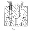
- the die shown in Figure 1 comprises opposing side walls 1, a base 2 and end walls (not shown) which may be made of any suitable material.
- the punch comprises a pair of elongate outer plungers 3 and a central plunger 4. Holes 5, 6 and 7 are shown in the base the outer plungers and the central plunger respectively, but it is not essential that holes should be formed in all of these components.
- the base 2 is shaped to correspond to the desired shape of the outer surface of the half pipe section
- the central plunger is shaped to correspond to the desired internal shape of the half pipe section
- the outer plungers are formed to determine the shape of the mating surfaces of the half pipe section.
- the mating faces are stepped, but any suitable shape may be adopted and the mating faces may be flat if desired.
- the female part of the die is first assembled by locating together the side walls 1, the base 2 and the end walls.
- Microporous insulation mixture 8 is then poured into the mould and the outer plungers 3 and the central plunger 4 are located into the top of the mould. Downwards pressure is applied to the plungers 3 and 4 so that the microporous insulation mixture is compacted with excess air escaping by way of the holes 5, 6 and 7.
- the pressure applied to the plunger 4 is controlled so that the rate of movement of the plunger 4 is different to the rate of movement of the plungers 3. Ideally, the plungers 3 will reach their final compaction point at the moment that the plunger 4 reaches the end of its travel, although the plungers 3 will travel further than the plunger 4.
- the vertical thickness of the final half pipe section in region 9 is less than the vertical thickness of region 10.
- the thickness of region 9 is substantially 25 mm whereas the thickness of region 10 is approximately 50 mm.
- the mixture behaves at first like a fluid and occupies the space beneath the plungers 3 and 4 with substantially an even density.
- the density of the mixture is increased by compaction from its original free flow density of typically 40 Kg/m 3 to about 100 Kg/m 3 the mixture readily flows, but at densities above about 100 Kg/m 3 the mixture does not readily flow so that as the mixture is further compacted the mixture in a column 11 will constitute region 9 and the mixture in a column 12 will constitute region 10.
- the degree of compaction of column 11 must be the same as the degree of compaction of column 12.
- the height of column 11 at a density of 100 Kg/m 3 must be substantially 75 mm and the height of column 12 at the same density must be substantially 150 mm. It follows that the travel or stroke cycle of the plunger 4 from a point equivalent to substantially 100Kg/m 3 density to final compaction is substantially 50 mm, whereas the travel or stroke cycle of the plungers 3 from a point equivalent to substantially 100 Kg/m 3 density to final compaction is substantially 100 mm.
- the time taken for the outer plungers 3 to travel the 100 mm is the same as the time taken for the central plunger 4 to travel its 50 mm in order that the plungers 3 and 4 should reach the full extent of their travel substantially simultaneously.
- Such an arrangement results in a half pipe section moulding which has a uniform texture and is free from cracks, and which may be removed from the mould by simple ejection techniques or by dismantling the mould.
- composition of the microporous insulation mixture used to produce the final shaped article may consist of an intimate mixture of about 40 to 90 per cent by weight finely divided silica (pyrogenic silica or silica aerogel), up to 40 per cent by weight of an infra-red opacifier and up to 50 per cent by weight of a reinforcing fibre.
- finely divided silica pyrogenic silica or silica aerogel
- infra-red opacifier up to 50 per cent by weight of a reinforcing fibre.
- the opacifier may be a radiation scattering material having a high refractive index such as titania, alumina, zirconia, iron oxide or chrome oxide, a radiation absorbing material such as carbon black or a radiation reflecting material such as a metal.
- the opacifier may be in the form of a powder, short fibres or flakes.
- the reinforcing fibre may be, for example, ceramic fibre, glass fibre or other inorganic or organic fibre.
- a binding agent or a binding catalyst may be incorporated into the mixture.
- the density at which the microporous insulation mixture ceases to flow readily depends upon the relative proportions of the constituents used. However, the most effective distances of travel of the plungers 3 and 4 can readily be determined by simple tests which require no inventive capability.
- the movements of the plungers 3 and 4 may be controlled in a number of ways, but we have devised a particularly simple method which makes it possible to use the most inexpensive of presses, that is a single ram or platen press.
- a ram 13 of a press is arranged to be urged against a connecting portion 14 which interconnects the two outer plungers 3.
- a spring means 15 which acts between the connecting portion 14 and the central plunger 4.
- the spring means 15 may be, for example, a coil spring or, preferably, a block of compressible rubber.
- the properties of the spring means for example the thickness and the hardness of the compressible rubber, may be chosen to give good control of the relative movements of the plungers 3 and 4.
Landscapes
- Engineering & Computer Science (AREA)
- Chemical & Material Sciences (AREA)
- Ceramic Engineering (AREA)
- Manufacturing & Machinery (AREA)
- Mechanical Engineering (AREA)
- Materials Engineering (AREA)
- Structural Engineering (AREA)
- Organic Chemistry (AREA)
- Press-Shaping Or Shaping Using Conveyers (AREA)
- Processing And Handling Of Plastics And Other Materials For Molding In General (AREA)
- Thermal Insulation (AREA)
- Insulating Bodies (AREA)
- Powder Metallurgy (AREA)
- Fish Paste Products (AREA)
- Glass Melting And Manufacturing (AREA)
- Insulating Of Coils (AREA)
- Insulation, Fastening Of Motor, Generator Windings (AREA)
Priority Applications (1)
| Application Number | Priority Date | Filing Date | Title |
|---|---|---|---|
| AT86305805T ATE87287T1 (de) | 1985-08-16 | 1986-07-29 | Verfahren und vorrichtung zur herstellung von geformten isolierenden gegenstaenden. |
Applications Claiming Priority (2)
| Application Number | Priority Date | Filing Date | Title |
|---|---|---|---|
| GB858520564A GB8520564D0 (en) | 1985-08-16 | 1985-08-16 | Forming shaped pieces of insulation |
| GB8520564 | 1985-08-16 |
Publications (3)
| Publication Number | Publication Date |
|---|---|
| EP0212872A2 true EP0212872A2 (de) | 1987-03-04 |
| EP0212872A3 EP0212872A3 (en) | 1988-06-08 |
| EP0212872B1 EP0212872B1 (de) | 1993-03-24 |
Family
ID=10583873
Family Applications (1)
| Application Number | Title | Priority Date | Filing Date |
|---|---|---|---|
| EP86305805A Expired - Lifetime EP0212872B1 (de) | 1985-08-16 | 1986-07-29 | Verfahren und Vorrichtung zur Herstellung von geformten isolierenden Gegenständen |
Country Status (11)
| Country | Link |
|---|---|
| US (2) | US4801415A (de) |
| EP (1) | EP0212872B1 (de) |
| JP (1) | JP2573484B2 (de) |
| AT (1) | ATE87287T1 (de) |
| AU (1) | AU599040B2 (de) |
| CA (1) | CA1288208C (de) |
| DE (1) | DE3688112T2 (de) |
| ES (1) | ES2001230A6 (de) |
| GB (1) | GB8520564D0 (de) |
| NZ (1) | NZ216932A (de) |
| ZA (1) | ZA866174B (de) |
Cited By (1)
| Publication number | Priority date | Publication date | Assignee | Title |
|---|---|---|---|---|
| FR2662381A1 (fr) * | 1990-05-22 | 1991-11-29 | Alsetex | Procede pour l'obtention de revetement pour charges creuses en materiau fritte. |
Families Citing this family (11)
| Publication number | Priority date | Publication date | Assignee | Title |
|---|---|---|---|---|
| JPS63134603A (ja) * | 1986-11-25 | 1988-06-07 | Kato Hatsujo Kaisha Ltd | プ−リ−の製造方法 |
| US5192560A (en) * | 1989-03-07 | 1993-03-09 | Canon Kabushiki Kaisha | Variable mold apparatus |
| US5030402A (en) * | 1989-03-17 | 1991-07-09 | Zachariades Anagnostis E | Process for producing a new class of ultra-high-molecular-weight polyethylene orthopaedic prostheses with enhanced mechanical properties |
| US5380482A (en) * | 1991-10-18 | 1995-01-10 | Aspen Research, Inc. | Method of manufacturing ingots for use in making objects having high heat, thermal shock, corrosion and wear resistance |
| JP3687492B2 (ja) * | 2000-06-21 | 2005-08-24 | 株式会社村田製作所 | 誘電体ブロックのプレス成形方法 |
| US20030090042A1 (en) * | 2002-11-13 | 2003-05-15 | Sevigny Robert S | Self adjustable variable shape forming plug assist assembly |
| US7108823B2 (en) * | 2003-09-25 | 2006-09-19 | Berry Plastics Corporation | Staged compression molding process |
| US20070023965A1 (en) * | 2004-09-23 | 2007-02-01 | Berry Plastics Corporation | Staged compression molding process |
| DE102006009953A1 (de) * | 2006-03-03 | 2007-09-06 | Wacker Chemie Ag | Verfahren zur Wiederverwertung von hochsiedenden Verbindungen innerhalb eines Chlorsilanverbundes |
| US20080241490A1 (en) * | 2007-04-02 | 2008-10-02 | Physical Sciences, Inc. | Sprayable Aerogel Insulation |
| FR3157830A1 (fr) * | 2024-01-02 | 2025-07-04 | Cerib | Procédé de fabrication d’un bloc de maçonnerie en béton calibré à une hauteur déterminée, et dispositif de compactage assurant l’obtention d’un tel bloc de maçonnerie |
Family Cites Families (18)
| Publication number | Priority date | Publication date | Assignee | Title |
|---|---|---|---|---|
| CA692421A (en) * | 1964-08-11 | Formwood Limited | Method of and pressing tool for the manufacture of chip mouldings with unequal wall thicknesses | |
| GB912847A (de) * | ||||
| US937105A (en) * | 1908-10-10 | 1909-10-19 | Claudius Brissell Jenkins | Mold for drain-pipe sections. |
| US1807443A (en) * | 1928-11-22 | 1931-05-26 | Vesta M Senn | Pressure equalizing mechanism for multiple dies |
| US2033411A (en) * | 1932-09-06 | 1936-03-10 | Pacific Lumber Co | Manufacture of artificial lumber and pressed and molded products |
| US2181619A (en) * | 1935-12-16 | 1939-11-28 | Standard Pyrometric Cone Compa | Press for producing pyrometric cones |
| US2306443A (en) * | 1939-04-19 | 1942-12-29 | Quaker Mfg Company | Pilot ring for oil burners |
| US2360443A (en) * | 1941-07-12 | 1944-10-17 | Onions John Henry | Apparatus for manufacturing grinding tools |
| GB809672A (en) * | 1954-07-02 | 1959-03-04 | Coal Industry Patents Ltd | Improvements in and relating to moulding presses |
| US2888715A (en) * | 1957-03-21 | 1959-06-02 | Stokes F J Corp | Proportional pressing |
| US3166617A (en) * | 1961-05-01 | 1965-01-19 | Werz Furnier Sperrholz | Method and apparatus for producing articles of molded particle board |
| US3647332A (en) * | 1969-08-29 | 1972-03-07 | Parker Hannifin Corp | Hydraulic press |
| US4073851A (en) * | 1970-07-15 | 1978-02-14 | Werzalit Pressholzwerk J.F. Werz K.G. | Method of making molded bodies from ligno-cellulose particles |
| DE2438836B2 (de) * | 1974-08-13 | 1977-09-01 | D. Swarovski & Co, Glasschleiferei, Wattens, Tirol (Österreich) | Verfahren zur herstellung von formkoerpern aus plastisch formbaren massen, insbesondere glas, und dafuer geeignete vorrichtung |
| GB1580909A (en) * | 1977-02-10 | 1980-12-10 | Micropore Internatioonal Ltd | Thermal insulation material |
| DE3038142C2 (de) * | 1980-10-09 | 1983-12-01 | Brown, Boveri & Cie Ag, 6800 Mannheim | Thermische Isolierung |
| DE3339487A1 (de) * | 1983-10-31 | 1985-05-15 | Bühler, Eugen, Dipl.-Ing., 8877 Burtenbach | Verfahren zur herstellung eines trockengepressten formlings aus trockener, rieselfaehiger formmasse, insbesondere keramischer formmasse |
| JPH0230252Y2 (de) * | 1985-04-12 | 1990-08-15 |
-
1985
- 1985-08-16 GB GB858520564A patent/GB8520564D0/en active Pending
-
1986
- 1986-07-22 NZ NZ216932A patent/NZ216932A/en unknown
- 1986-07-29 AT AT86305805T patent/ATE87287T1/de active
- 1986-07-29 DE DE8686305805T patent/DE3688112T2/de not_active Expired - Fee Related
- 1986-07-29 EP EP86305805A patent/EP0212872B1/de not_active Expired - Lifetime
- 1986-08-04 US US06/894,496 patent/US4801415A/en not_active Expired - Lifetime
- 1986-08-14 ES ES8601118A patent/ES2001230A6/es not_active Expired
- 1986-08-15 AU AU61528/86A patent/AU599040B2/en not_active Ceased
- 1986-08-15 CA CA000516076A patent/CA1288208C/en not_active Expired - Fee Related
- 1986-08-15 ZA ZA866174A patent/ZA866174B/xx unknown
- 1986-08-15 JP JP61190737A patent/JP2573484B2/ja not_active Expired - Lifetime
-
1987
- 1987-04-28 US US07/043,544 patent/US4797082A/en not_active Expired - Lifetime
Cited By (1)
| Publication number | Priority date | Publication date | Assignee | Title |
|---|---|---|---|---|
| FR2662381A1 (fr) * | 1990-05-22 | 1991-11-29 | Alsetex | Procede pour l'obtention de revetement pour charges creuses en materiau fritte. |
Also Published As
| Publication number | Publication date |
|---|---|
| EP0212872B1 (de) | 1993-03-24 |
| JPS6285903A (ja) | 1987-04-20 |
| ES2001230A6 (es) | 1988-05-01 |
| ZA866174B (en) | 1987-07-29 |
| AU599040B2 (en) | 1990-07-12 |
| US4797082A (en) | 1989-01-10 |
| AU6152886A (en) | 1987-02-19 |
| DE3688112D1 (de) | 1993-04-29 |
| US4801415A (en) | 1989-01-31 |
| EP0212872A3 (en) | 1988-06-08 |
| JP2573484B2 (ja) | 1997-01-22 |
| NZ216932A (en) | 1987-10-30 |
| DE3688112T2 (de) | 1993-07-01 |
| GB8520564D0 (en) | 1985-09-25 |
| CA1288208C (en) | 1991-09-03 |
| ATE87287T1 (de) | 1993-04-15 |
Similar Documents
| Publication | Publication Date | Title |
|---|---|---|
| EP0212872B1 (de) | Verfahren und Vorrichtung zur Herstellung von geformten isolierenden Gegenständen | |
| RU2010676C1 (ru) | Способ прессования многослойных заготовок из различных порошковых материалов с вертикальным расположением слоев | |
| US4414028A (en) | Method of and apparatus for sintering a mass of particles with a powdery mold | |
| US5077002A (en) | Process for shaping any desired component using a powder as the starting material | |
| US4370285A (en) | Method of production of a lightweight building element | |
| US4483892A (en) | Wear resistant annular insert and process for making same | |
| RU2040368C1 (ru) | Способ холодного формования заготовок из порошковых материалов и устройство для его осуществления | |
| US5895616A (en) | Method of preforming friction material | |
| US3985844A (en) | Process for the production of prismatic graphite molded articles for high temperature fuel elements | |
| RU2083328C1 (ru) | Способ импульсного прессования твердых порошковых материалов и устройство для его осуществления | |
| EP0339497A3 (de) | Verfahren und Vorrichtung zum Strangpressen oder Strangrohrpressen | |
| RU2052322C1 (ru) | Способ изготовления газонепроницаемых низкопористых порошковых материалов | |
| SU562996A1 (ru) | Способ изготовлени изделий из политетрафторэтилена | |
| GB2025837A (en) | Compression mouldin ceramic insulators | |
| Timokhova | Design specifics of quasi-isostatic molds | |
| JPH04157102A (ja) | 粉末成形用金型 | |
| SU703237A1 (ru) | Способ прессовани изделий из порошка и устройство дл его осуществлени | |
| JPH0584713A (ja) | セラミツクスハニカム構造体の製造方法 | |
| SU1430280A1 (ru) | Способ изготовлени пустотелых изделий из пресс-порошков и пресс-форма дл изготовлени пустотелых изделий из пресс-порошков | |
| SU872029A1 (ru) | Устройство дл формовани длинномерных полых изделий из металлических порошков | |
| SU1524967A1 (ru) | Способ прессовани биметаллических изделий из порошков | |
| SU683996A1 (ru) | Устройство дл наполнени емкостей | |
| JPH01119604A (ja) | 粉末成形法 | |
| RU2140355C1 (ru) | Способ горячего прессования изделий из порошкообразного материала и устройство (варианты) для его осуществления | |
| SU742132A2 (ru) | Устройство дл образовани пустот в изделии |
Legal Events
| Date | Code | Title | Description |
|---|---|---|---|
| PUAI | Public reference made under article 153(3) epc to a published international application that has entered the european phase |
Free format text: ORIGINAL CODE: 0009012 |
|
| 17P | Request for examination filed |
Effective date: 19860815 |
|
| AK | Designated contracting states |
Kind code of ref document: A2 Designated state(s): AT BE CH DE FR GB IT LI NL SE |
|
| PUAL | Search report despatched |
Free format text: ORIGINAL CODE: 0009013 |
|
| RHK1 | Main classification (correction) |
Ipc: C04B 28/24 |
|
| AK | Designated contracting states |
Kind code of ref document: A3 Designated state(s): AT BE CH DE FR GB IT LI NL SE |
|
| 17Q | First examination report despatched |
Effective date: 19900809 |
|
| GRAA | (expected) grant |
Free format text: ORIGINAL CODE: 0009210 |
|
| AK | Designated contracting states |
Kind code of ref document: B1 Designated state(s): AT BE CH DE FR GB IT LI NL SE |
|
| REF | Corresponds to: |
Ref document number: 87287 Country of ref document: AT Date of ref document: 19930415 Kind code of ref document: T |
|
| REF | Corresponds to: |
Ref document number: 3688112 Country of ref document: DE Date of ref document: 19930429 |
|
| ITF | It: translation for a ep patent filed | ||
| ET | Fr: translation filed | ||
| ITTA | It: last paid annual fee | ||
| PLBE | No opposition filed within time limit |
Free format text: ORIGINAL CODE: 0009261 |
|
| STAA | Information on the status of an ep patent application or granted ep patent |
Free format text: STATUS: NO OPPOSITION FILED WITHIN TIME LIMIT |
|
| 26N | No opposition filed | ||
| EAL | Se: european patent in force in sweden |
Ref document number: 86305805.3 |
|
| PGFP | Annual fee paid to national office [announced via postgrant information from national office to epo] |
Ref country code: GB Payment date: 20000609 Year of fee payment: 15 |
|
| PGFP | Annual fee paid to national office [announced via postgrant information from national office to epo] |
Ref country code: AT Payment date: 20000615 Year of fee payment: 15 |
|
| PGFP | Annual fee paid to national office [announced via postgrant information from national office to epo] |
Ref country code: BE Payment date: 20000627 Year of fee payment: 15 |
|
| PGFP | Annual fee paid to national office [announced via postgrant information from national office to epo] |
Ref country code: FR Payment date: 20000628 Year of fee payment: 15 |
|
| PGFP | Annual fee paid to national office [announced via postgrant information from national office to epo] |
Ref country code: SE Payment date: 20000717 Year of fee payment: 15 |
|
| PGFP | Annual fee paid to national office [announced via postgrant information from national office to epo] |
Ref country code: NL Payment date: 20000731 Year of fee payment: 15 |
|
| PGFP | Annual fee paid to national office [announced via postgrant information from national office to epo] |
Ref country code: CH Payment date: 20000808 Year of fee payment: 15 |
|
| PGFP | Annual fee paid to national office [announced via postgrant information from national office to epo] |
Ref country code: DE Payment date: 20000929 Year of fee payment: 15 |
|
| PG25 | Lapsed in a contracting state [announced via postgrant information from national office to epo] |
Ref country code: GB Free format text: LAPSE BECAUSE OF NON-PAYMENT OF DUE FEES Effective date: 20010729 Ref country code: AT Free format text: LAPSE BECAUSE OF NON-PAYMENT OF DUE FEES Effective date: 20010729 |
|
| PG25 | Lapsed in a contracting state [announced via postgrant information from national office to epo] |
Ref country code: SE Free format text: LAPSE BECAUSE OF NON-PAYMENT OF DUE FEES Effective date: 20010730 |
|
| PG25 | Lapsed in a contracting state [announced via postgrant information from national office to epo] |
Ref country code: LI Free format text: LAPSE BECAUSE OF NON-PAYMENT OF DUE FEES Effective date: 20010731 Ref country code: CH Free format text: LAPSE BECAUSE OF NON-PAYMENT OF DUE FEES Effective date: 20010731 Ref country code: BE Free format text: LAPSE BECAUSE OF NON-PAYMENT OF DUE FEES Effective date: 20010731 |
|
| BERE | Be: lapsed |
Owner name: MICROPORE INTERNATIONAL LTD Effective date: 20010731 |
|
| PG25 | Lapsed in a contracting state [announced via postgrant information from national office to epo] |
Ref country code: NL Free format text: LAPSE BECAUSE OF NON-PAYMENT OF DUE FEES Effective date: 20020201 |
|
| EUG | Se: european patent has lapsed |
Ref document number: 86305805.3 |
|
| REG | Reference to a national code |
Ref country code: CH Ref legal event code: PL |
|
| GBPC | Gb: european patent ceased through non-payment of renewal fee |
Effective date: 20010729 |
|
| PG25 | Lapsed in a contracting state [announced via postgrant information from national office to epo] |
Ref country code: FR Free format text: LAPSE BECAUSE OF NON-PAYMENT OF DUE FEES Effective date: 20020329 |
|
| NLV4 | Nl: lapsed or anulled due to non-payment of the annual fee |
Effective date: 20020201 |
|
| PG25 | Lapsed in a contracting state [announced via postgrant information from national office to epo] |
Ref country code: DE Free format text: LAPSE BECAUSE OF NON-PAYMENT OF DUE FEES Effective date: 20020501 |
|
| REG | Reference to a national code |
Ref country code: FR Ref legal event code: ST |
|
| PG25 | Lapsed in a contracting state [announced via postgrant information from national office to epo] |
Ref country code: IT Free format text: LAPSE BECAUSE OF NON-PAYMENT OF DUE FEES;WARNING: LAPSES OF ITALIAN PATENTS WITH EFFECTIVE DATE BEFORE 2007 MAY HAVE OCCURRED AT ANY TIME BEFORE 2007. THE CORRECT EFFECTIVE DATE MAY BE DIFFERENT FROM THE ONE RECORDED. Effective date: 20050729 |