EP0212938A2 - Verfahren zur Erzeugung einer Legierungsschicht auf einem Aluminiumlegierungssubstrat durch Auftragen eines ein Legierungsbestandteil und Wismut enthaltendes Pulver und Bestrahlung mit einem CO2-Laser - Google Patents
Verfahren zur Erzeugung einer Legierungsschicht auf einem Aluminiumlegierungssubstrat durch Auftragen eines ein Legierungsbestandteil und Wismut enthaltendes Pulver und Bestrahlung mit einem CO2-Laser Download PDFInfo
- Publication number
- EP0212938A2 EP0212938A2 EP86306245A EP86306245A EP0212938A2 EP 0212938 A2 EP0212938 A2 EP 0212938A2 EP 86306245 A EP86306245 A EP 86306245A EP 86306245 A EP86306245 A EP 86306245A EP 0212938 A2 EP0212938 A2 EP 0212938A2
- Authority
- EP
- European Patent Office
- Prior art keywords
- powder
- alloy
- alloying
- aluminum alloy
- approximately
- Prior art date
- Legal status (The legal status is an assumption and is not a legal conclusion. Google has not performed a legal analysis and makes no representation as to the accuracy of the status listed.)
- Granted
Links
Images





Classifications
-
- B—PERFORMING OPERATIONS; TRANSPORTING
- B23—MACHINE TOOLS; METAL-WORKING NOT OTHERWISE PROVIDED FOR
- B23K—SOLDERING OR UNSOLDERING; WELDING; CLADDING OR PLATING BY SOLDERING OR WELDING; CUTTING BY APPLYING HEAT LOCALLY, e.g. FLAME CUTTING; WORKING BY LASER BEAM
- B23K35/00—Rods, electrodes, materials, or media, for use in soldering, welding, or cutting
- B23K35/22—Rods, electrodes, materials, or media, for use in soldering, welding, or cutting characterised by the composition or nature of the material
- B23K35/24—Selection of soldering or welding materials proper
- B23K35/28—Selection of soldering or welding materials proper with the principal constituent melting at less than 950°C
- B23K35/286—Al as the principal constituent
Definitions
- the present invention relates to a method for forming an alloy layer upon a substrate metal which is an alloy of aluminum, and more particularly relates to such a method for forming an alloy layer upon a substrate metal, in which the layer is formed by the use of a C0 2 laser.
- the heating source which is utilized is a CO 2 type laser of the type which is conventionally used for metal processing and the like, and when the substrate metal material is aluminum alloy which is a typical metal alloy material the surface of parts made from which it is desirable to reinforce, because the aluminum alloy substrate material has a low electrical resistance it is not possible to easily fuse the surface portion of said aluminum alloy substrate material and the alloy material to be added thereto, and it is not in practice possible to form the desired reinforcing surface alloy layer. This is because the layer absorption X is determined by the relationship
- a C0 2 laser emits thermal energy which is electromagnetic radiation in the near infrared wave band with a wave length of about 10.6 microns, and aluminum alloys generally have a low electrical resistance.
- the ability of the alloy material to form a solid solution with the material of the metal substrate material (the so called "wettability" thereby) and the uniformity of the form of the compound in deposition in the alloy layer are very important.
- the degree of solid solution of the alloy material can in principle be determined from conventional equilibrium state diagrams and various other research data, and it is desirable in order to form an appropriate alloy layer to make the degree of solid solution of the alloy material relatively high.
- the inventors of the present invention considered the various problems detailed above in the case when an alloy layer is to be formed on the surface of an aluminum alloy substrate material, from the point of view of the desirability of utilizing a CO - laser as the heat source for melting and fusing together said alloy layer; and, as a result of various experimental researches to be detailed hereinafter, the present inventors have come to the knowledge that it is effective to include a proportion of either silicon or bismuth along with the material that is to be alloyed with the aluminum alloy substrate material, for providing eutectic crystallization as described above.
- a method for forming an alloy layer on the surface of an aluminum alloy substrate comprising the steps of: (a) disposing an powder for alloying, containing a substance to be alloyed with said aluminum alloy substrate, and an element selected from the group consisting of silicon and bismuth, upon the surface of said aluminum alloy substrate; and: (b) irradiating with a C0 2 laser said powder for alloying as disposed upon said surface of said aluminum alloy substrate, so as to melt and fuse said powder for alloying and a surface portion of said aluminum alloy substrate and so as to alloy them together.
- the powder for alloying includes either silicon or bismuth, in addition to the substance, such as for example stellite, copper or nickel, for being alloyed with the aluminum alloy substrate, thereby said powder for alloying has a relatively high electrical resistance as compared with the element for being alloyed with the substrate by itself; and thereby the absorption of the beam emitted by the laser by said powder for alloying is relatively high, and therefore said powder for alloying fuses and melts relatively easily.
- the laser beam absorption thereby is further enhanced, and as a result the surface portion of the aluminum alloy substrate is relatively easily fused.
- an alloy layer can be much more easily formed on the surface of the aluminum alloy substrate material block, and this alloy layer can be formed of a relatively excellent quality not substantially including any blow holes or other such defects.
- the fusing and the melting of the alloying powder can be performed relatively easily, as compared with the case when no such additive as the silicon or bismuth is employed and the element to be alloyed with the aluminum alloy substrate is attempted to be alloyed by itself by laser irradiation with a C0 2 laser as was the case in the prior art, therefore it is possible to utilize as alloying powders powders including elements to be alloyed which cannot be very easily fused by a C0 2 laser, due to the increased efficacy of the process; and this wider possible range of choice for the element to be alloyed makes it possible to form alloy layers having a much wider range of desirable characteristics such as corrosion resistance or the like, as required for the surface portion of the aluminum alloy matrix metal.
- the above specified and other objects are more particularly attained by a method for forming an alloy layer on the surface of an aluminum alloy substrate as specified above, wherein said powder for alloying is a mixture of a powder of said substance to be alloyed with said aluminum alloy substrate and a powder of said element selected from the group consisting of silicon and bismuth.
- the above specified and other objects are more particularly attained by a method for forming an alloy layer on the surface of an aluminum alloy substrate as specified above, wherein said powder for alloying is a powder of an alloy of said substance to be alloyed with said aluminum alloy substrate and said element selected from the group consisting of silicon and bismuth.
- the content of silicon or bismuth of the powder for alloying is too low, it becomes difficult to form the alloy layer properly. Therefore, according to one more particular specialization of the present invention, when a mixture of powders as specified above is utilized as the powder for alloying: if the added substance is silicon, the above specified and other objects are more particularly attained by a method for forming an alloy layer on the surface of an aluminum alloy substrate as specified above, wherein the silicon content of said powder for alloying is at least about 17%; and more preferably said silicon content of said powder for alloying will be at least about 35%; and even more preferably said silicon content of said powder for alloying will be at least about 42%; but, if the added substance is bismuth, the above specified and other objects are more particularly attained by a method for forming an alloy layer on the surface of an aluminum alloy substrate as specified above, wherein the bismuth content of said powder for alloy
- a powdered alloy as specified above when utilized as the powder for alloying: if the added substance is silicon, the above specified and other objects are more particularly attained by a method for forming an alloy layer on the surface of an aluminum alloy substrate as specified above, wherein the silicon content of said powder for alloying is at least about 13%; and more preferably said silicon content of said powder for alloying will be at least about 26%; and even more preferably said silicon content of said powder for alloying will be at least about 30%; but, if the added substance is bismuth, the above specified and other objects are more particularly attained by a method for forming an alloy layer on the surface of an aluminum alloy substrate as specified above, wherein the bismuth content of said powder for alloying is at least about 15%; and more preferably said bismuth content of said powder for alloying will be at least about 28%; and even more preferably said bismuth content of said powder for alloying will be at least about 32%.
- the above specified and other objects are more particularly attained by a method for forming an alloy layer on the surface of an aluminum alloy substrate as specified above, wherein the average particle size of the silicon powder included in said powder for alloying is not more than about -24 mesh; and more preferably said silicon particle average particle size will be not more than about -32 mesh; and even more preferably said silicon particle average particle size will be not more than about -42 mesh; but, if the added substance is bismuth, the above specified and other objects are more particularly attained by a method for forming an alloy layer on the surface of an aluminum alloy substrate as specified above, wherein the average particle size of the bismuth powder included in said powder for alloying is not more than about -42 mesh; and more preferably said bismuth particle average particle size will be not more than about -48 mesh; and even more preferably said bismuth particle average particle size will be
- a powdered alloy as specified above when utilized as the powder for alloying: if the added substance is silicon, the above specified and other objects are more particularly attained by a method for forming an alloy layer on the surface of an aluminum alloy substrate as specified above, wherein the average particle size of the silicon powder included in said powder for alloying is not more than about -24 mesh; and more preferably said silicon particle average particle size will be not more than about -32 mesh; and even more preferably said silicon particle average particle size will be not more than about -42 mesh; but, if the added substance is bismuth, the above specified and other objects are more particularly attained by a method for forming an alloy layer on the surface of an aluminum alloy substrate as specified above, wherein the average particle size of the bismuth powder included in said powder for alloying is not more than about -42 mesh; and more preferably said bismuth particle average particle size will be not more than about -48 mesh; and even more preferably said bismuth particle average particle size
- the alloy of said powder for alloying and said surface portion of said aluminum alloy substrate, as fused and melted by said CO 2 laser may be cooled and solidified principally by heat conduction to the main body of said aluminum alloy substrate. According to this, no special means is required for cooling said fused and molten portion, and yet said molten portion is relatively rapidly cooled, as a result of which the crystalline structure thereof is relatively fine, and therefore an alloy layer of high strength and good hardness can be formed on the surface of the aluminum alloy substrate material piece.
- said irradiation of said powder for alloying as disposed upon said surface of said aluminum alloy substrate by said C0 2 laser may be performed in an inert atmosphere.
- the inert atmosphere may be provided by a flux such as in the case of welding, but for positive results and to avoid envelopment of the work in slag, and to improve workability, it is preferable to employ an inert gas atmosphere composed of a gas such as argon or helium or the like, or indeed a vacuum atmosphere.
- said powder for alloying may be disposed upon said surface of said aluminum alloy substrate by being supplied in loose powder form thereonto into the path of the beam produced by said C0 2 laser.
- a carrier inert gas may be fed into said loose powder form supply of said powder for alloying.
- said powder for alloying may be disposed upon said surface of said aluminum alloy substrate by being applied thereon as a paste including a binder, such as for example an aqueous solution of polyvinyl alcohol or a mixture of acrylic and thinner.
- a paste including a binder such as for example an aqueous solution of polyvinyl alcohol or a mixture of acrylic and thinner.
- the application of such a paste upon said surface of said aluminum alloy substrate may be by application by a spatula or via a tube, and, in the case where the thickness of the alloy layer to be formed on the surface of the aluminum alloy substrate is small, said powder for alloying may be formed into a slurry by dispersal in a solvent such as for example an aqueous solution of polyvinyl alcohol, and then this slurry may be applied to the surface of the aluminum alloy substrate by painting with a brush or the like, by spraying, or by dipping.
- a solvent such as for example an aqueous solution of polyvinyl alcohol
- the thermal fusing process by the beam of the CO 2 laser it is preferable for the thermal fusing process by the beam of the CO 2 laser to be performed when it is ensured that the slurry contains substantially no water, i.e. after sufficient drying at an appropriate temperature range in an atmosphere such that pores are not produced in the surface portion of the slurry layer and such that said surface portion of the slurry layer is not substantially oxidized.
- silicon powder is used for admixture with the alloy material. This is the first of the two materials that have been found by the present inventors to be suitable for this application.
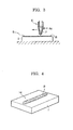
- Figs.1 through 4 show successive stages of the general method of practice of the first set of preferred embodiments of the alloy layer on substrate forming method of the present invention.
- a first quantity designated as "A" of alloy powder was produced by evenly combining together in a weight ratio of approximately 1:1 a quantity of silicon powder of average particle size approximately -50 mesh and a quantity of stellite alloy powder (composition approximately 24% chromium, approximately 4% tungsten, approximately 8% nickel, approximately 0.5% silicon, approximately 0.1% boron, not more than 0.4% carbon, and remainder substantially cobalt) of average particle size approximately -100 mesh.
- a second quantity designated as "B" of alloy powder was produced by evenly combining together in a weight ratio of approximately 11 a quantity of silicon powder of average particle size approximately -250 mesh and a quantity of similarly composed stellite alloy powder of average particle size approximately -100 mesh.
- alloy powder quantities "A” and "B” were, as will be seen, constituted so as to be suitable for practice of the two preferred embodiments of the method of the present invention included in the first set thereof. And for the practice of a comparison method, not according to the present invention, there was produced a quantity designated as "C" of a third powder, being similarly composed stellite powder only, of average particle size approximately -100 mesh. And, next, to each of these powders for alloying there was added a quantity of 5% aqueous solution of polyvinyl alcohol, to serve as a binder, and thus in each of the three cases there was formed a paste with a viscosity higher than that of water and lower than that of clay.
- substrate material test sample pieces 1 were prepared, each being a cuboidal block with dimensions approximately 70 mm x 40 mm x 10 mm, and being made of aluminum alloy of JIS (Japanese Industrial Standard) ADC-10. And, as shown in the side perspective view of Fig. 1 which shows the first stage of practice of these first set of preferred embodiments, on each of the 70 mm x 40 mm surfaces denoted as la of three of these four aluminum alloy substrate material pieces 1 there were laid two guide plates 2 and 3 of suitable material, of thickness about 1 mm, with their longer edges parallel to and confronting one another and separated by about 5 mm.
- JIS Japanese Industrial Standard
- each of the assemblies as shown in Fig. 1 was heated to a temperature of about 100 C in a drying oven and was maintained at said temperature for about one hour; thus in each case the alloy powder paste quantity 4 was thoroughly dried.
- the two guide plates 2 and 3 were removed, to leave as shown in Fig. 2 in perspective view the block 1 of aluminum alloy substrate material with a strip layer 5 of the corresponding alloy powder laid along its 70 mm x 40 mm surface la parallel to and midway between the long sides thereof, said strip layer 5 being bound together and congealed to the block 1 by the hardened binder.
- said strip layer 5 had width about 5 mm, thickness about 1.0 mm, and length about 60 mm.
- a strip piece designated as "D” made of so called D-6k alloy material (composition approximately 30% chromium, approximately 4.5% tungsten, approximately 1.0% carbon, and remainder substantially cobalt), of dimensions width about 5 mm, thickness about 05 mm, and length about 60 mm.
- a laser gun 6 was scanned in one pass along each of these strips 5 of material (either congealed alloy powder or strip material) for being alloyed with the substrate aluminum alloy block 1, from one end thereof to the other, while simultaneously a stream of argon gas was emitted from the end of said laser gun 6, said argon gas stream acting as a shield gas.
- the laser gun 6 was at this time operated so as to emit laser radiation, denoted in Fig. 3 as 7, and this process caused local heating of the strip 5 of material for alloying and melting thereof.
- the laser output was about 2.0 kilowatts; the output mode was multi mode; the beam pattern was elliptical, with the long diameter about 5 mm and the short diameter about 3.5 mm; the laser scanning speed was about 300 mm per minute; and the flow rate of the argon shield gas was about 35 liters per minute.
- a bead portion 8 of fused and melted together alloy material (powder or strip) and substrate aluminum alloy material was formed along the 70 mm x 40 mm surface la of each substrate material block 1, parallel to and midway between the long sides thereof. During this process, the molten portion was cooled rapidly, principally by absorption of the heat therein by the main body of the substrate material block 1.
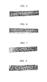
- Figs. 5 through 8 are plan views showing the bead portions 8 (i.e., the alloy layers) formed in each of the four cases described above, by employing the alloy materials "A", “B", “C”, and “D” respectively; thus, Figs. 5 and 6 were made according to the two preferred embodiments included in the first set of preferred embodiments of the alloy layer forming method of the present invention, by utilizing silicon powder mixed in with the stellite alloy material powder, while Figs. 7 and 8 were made by comparison methods not according to the present invention. Further, Figs.
- the alloy layer bead portion 8 was about 1.8 mm by about 4.2 mm in cross sectional dimensions, had surface hardness about 350 to 450, and had good surface appearance; in the case of the second one of said first set of preferred embodiments of the present invention which utilized the powder alloy material "B”, the alloy layer bead portion 8 was about 1.6 mm by about 4.0 mm in cross sectional dimensions, had surface hardness about 150 to 200, and likewise had good surface appearance; in the case of the first comparison method which utilized the powder alloy material "C” which contained only stellite powder but contained substantially no silicon powder, the alloy layer bead portion 8 was not properly formed, insofar as it could
- the laser fusing step performed during the practice of the second preferred embodiment of the method for forming an alloy layer on a substrate of the present invention is shown in side view in Fig. 11, in a similar manner to Fig. 3 relating to the first preferred embodiment.
- this second preferred embodiment was performed as follows. Initially, a quantity of alloy powder was produced by powdering to approximately -100 mesh a quantity of silicon - copper alloy (composition approximately 80% copper, and remainder substantially silicon). Next, a substrate material test sample piece 9 was prepared, of substantially the same dimensions of approximately 70 mm x 40 mm x 10 mm as in the case of the first set of preferred embodiments, and being made of substantially the same type of aluminum alloy of JIS (Japanese Industrial Standard) ADC-10.
- JIS Japanese Industrial Standard
- a CO 2 laser gun 10 was scanned in one pass along this substrate aluminum alloy block 9, from one end thereof to the other along the central portion of a 70 x 40 mm face 9a thereof and parallel to the 70 mm long sides of said face 9a, while simultaneously a stream of argon gas was emitted from the end of said laser gun 10, said argon gas stream acting as a shield gas; and, further, onto said upper face 9a of said alloy block 9 just into the path of said laser gun 10 and before it there was fed a steady stream of the above described alloy powder, a mass 12 of which was held in a hopper 11 a lower portion of which opened into an intermediate position along a downwardly sloping pipe 13 from which said alloy powder stream thus sifted and emerged, along with another admixture stream of argon gas which further was fed through said pipe 13 as a carrier gas.
- the laser gun 10 was at this time operated so as to emit laser radiation, denoted in Fig. 11 as 15, and this process caused local heating of the upper surface of the alloy block 9 and of the alloy powder just laid thereon, for fusingly alloying and melting thereof into a molten alloy layer 14 in the path of under and behind the laser gun 10, and said molten alloy layer hardened into a bead 16 trailing behind the laser gun 10.
- the laser gun output was about 2.0 kilowatts
- the output mode was multi mode
- the beam pattern was elliptical, with the long diameter about 5 mm and the short diameter about 35 mm
- the laser gun scanning speed was about 300 mm per minute
- the flow rate of the argon shield gas was about 35 liters per minute.
- Fig. 12 is a cross sectional optical photomicrograph view at an enlargement of 10X taken transversely through the bead portion 16 produced by said second preferred embodiment of the present invention alloy layer forming method.
- the portions showing up as black islands or specks of black color in the alloy layer are agglomerations of metallic compounds formed between copper and silicon.
- a central portion of the bead portion 16 illustrated in Fig. 12 was analyzed; and the composition thereof was found to be approximately 45% copper, approximately 8% silicon, and remainder substantially aluminum.
- the third preferred embodiment of the method for forming an alloy layer on a substrate of the present invention was performed as follows. Initially, a quantity of alloy powder was produced by powdering to approximately -100 mesh a quantity of silicon - nickel alloy (composition approximately 20% nickel, and remainder substantially silicon). And a substrate material test sample piece was prepared, of substantially the same dimensions of approximately 70 mm x 40 mm x 10 mm as in the case of the first set of preferred embodiments and the second preferred embodiment, and again being made of substantially the same type of aluminum alloy of JIS (Japanese Industrial Standard) ADC-10.
- JIS Japanese Industrial Standard
- an alloy layer bead was formed in substantially the same manner as in the second preferred embodiment disclosed above, i.e. by scanning a CO 2 laser gun in one pass along an upper face of this substrate aluminum alloy block while simultaneously feeding a steady stream of the above described alloy powder onto said upper face of said alloy block just into the path of said laser gun, with the laser gun being operated so as to emit laser radiation and so as to cause local heating of the upper surface of the alloy block and of the alloy powder just laid thereon for fusingly alloying and melting thereof into a molten alloy layer in the path of under and behind the laser gun, said molten alloy layer hardening into a bead trailing behind the laser gun.
- the parameters of this laser fusing process were substantially as in the case of the second preferred embodiment described above.
- Fig. 13 is a cross sectional optical photomicrograph view at an enlargement of 10X taken transversely through the bead portion produced by this third preferred embodiment of the present invention alloy layer forming method.
- the external appearance and tidyness of the bead is of good quality, and again an alloy layer with no substantial defects such as blow holes can be formed on the surface of the aluminum alloy substrate block.
- the portions showing up as specks of black color in the alloy layer are agglomerations of metallic compounds formed between nickel and silicon.
- a central portion of the bead portion 16 illustrated in Fig. 13 was analyzed; and the composition thereof was found to be approximately 7% to approximately 8% nickel, approximately 30% silicon, and remainder substantially aluminum.
- the fourth set of preferred embodiments of the method for forming an alloy layer on a substrate of the present invention were performed as follows. Initially, a set of seven quantities of alloy powder was produced by combining together in seven different weight ratios quantities of silicon powder the same as used in the first set of preferred embodiments (of average particle size approximately -250 mesh) and quantities of stellite alloy powder also the same as used in said first set of preferred embodiments. The silicon contents of these seven alloy powder quantities were respectively approximately 1.0%, approximately 11%, approximately 31%, approximately 50%, approximately 71%, approximately 91%, and approximately 98%.
- substrate material test sample pieces were prepared, each of substantially the same dimensions of approximately 70 mm x 40 mm x 10 mm as in the case of the previously described preferred embodiments, and again being made of substantially the same type of aluminum alloy of JIS (Japanese Industrial Standard) ADC-10.
- an alloy layer bead was formed in substantially the same manner as in the first preferred embodiment disclosed above, i.e. by laying a strip of the particular alloy powder along along an upper face of one of the substrate aluminum alloy blocks, said strip being congealed together and stuck to said substrate block upper face by the use of binder and by scanning a CO 2 laser gun along said alloy powder strip, with the laser gun being operated so as to emit laser radiation and so as to cause local heating of the upper surface of the alloy block and of the alloy powder strip laid thereon for fusingly alloying and melting thereof into a molten alloy layer in the path of under and behind the laser gun, said molten alloy layer hardening into a bead trailing behind the laser gun.
- the parameters of this laser fusing process were substantially as in the case of the first preferred embodiment described above.
- the alloying rate A (in percent) for each of the seven cases was then determined according to the following formula: where: A is the alloying rate; WO is the weight of the substrate aluminum alloy block alone, before alloying; Wl is the weight of the combination piece after the performance of the alloy layer forming method as described above, with sputter and the like removed; and Wa is the overall weight of the alloy powder quantity disposed on the surface of the substrate aluminum alloy block.
- Fig. 14 is a graph in which silicon content in percent of the alloy powder is shown along the horizontal axis and the above defined alloying rate A in percent is shown along the vertical axis. From this graph it will be understood that, in this case that as alloy powder is used a mixture of a silicon powder and a stellite alloy powder, it is preferable for the silicon content of the alloy powder to be at least 18%; that particularly, in this case, in order for the method according to the present invention to form properly an appropriate alloy layer said alloy powder silicon content should be at least 35%; and that even more preferably said silicon content should be at least 42%.
- the fifth set of preferred embodiments of the method for forming an alloy layer on a substrate of the present invention were performed as follows. Initially, a set of eight quantities of alloy powder was produced by combining together in eight different weight ratios quantities of silicon and quantities of stellite alloy, by fusing said silicon and stellite alloy together so as to alloy them together, and then by powdering the resulting alloy to an average particle size of approximately -100 mesh. The silicon contents of these eight alloy powder quantities were respectively approximately 2%, approximately 10%, approximately 21%, approximately 37%, approximately 49%, approximately 69%, approximately 89%, and approximately 97%.
- substrate material test sample pieces were prepared, each of substantially the same dimensions of approximately 70 mm x 40 mm x 10 mm as in the case of the previously described preferred embodiments, and again being made of substantially the same type of aluminum alloy of JIS (Japanese Industrial Standard) ADC-10.
- an alloy layer bead was formed in substantially the same manner as in the first preferred embodiment disclosed above, i.e. by laying a strip of the particular alloy powder along along an upper face of one of the substrate aluminum alloy blocks, said strip being congealed together and stuck to said substrate block upper face by the use of binder and by scanning a CO 2 laser gun along said alloy powder strip, with the laser gun being operated so as to emit laser radiation and so as to cause local heating of the upper surface of the alloy block and of the alloy powder strip laid thereon for fusingly alloying and melting thereof into a molten alloy layer in the path of under and behind the laser gun, said molten alloy layer hardening into a bead trailing behind the laser gun.
- the parameters of this laser fusing process were substantially as in the case of the first preferred embodiment described above.
- the alloying rate A (in percent) for each of the eight cases was then determined according to the formula described above.
- the silicon content of the alloy powder is at least 13%; that particularly, in this case, in order for the method according to the present invention to form properly an appropriate alloy layer said alloy powder silicon content should be at least 26%; and that even more preferably said silicon content should be at least 30%.
- the sixth set of preferred embodiments of the method for forming an alloy layer on a substrate of the present invention were performed as follows. Initially, a set of eight quantities of alloy powder was produced by combining together in eight different weight ratios quantities of silicon powder the same as used in the first set of preferred embodiments (of average particle size approximately -250 mesh) and quantities of copper alloy powder having an average particle size approximately -100 mesh. The silicon contents of these eight alloy powder quantities were respectively approximately 2%, approximately 16%, approximately 27%, approximately 36%, approximately 55%, approximately 70%, approximately 91%, and approximately 99%.
- substrate material test sample pieces were prepared, each of substantially the same dimensions of approximately 70 mm x 40 mm x 10 mm as in the case of the previously described preferred embodiments, and again being made of substantially the same type of aluminum alloy of JIS (Japanese Industrial Standard) ADC-10. And, in each of the eight cases, an alloy layer bead was formed in substantially the same manner as in the first preferred embodiment disclosed above, i.e.
- Fig. 15 is a graph similar to the Fig. 14 graph for the fourth and the fifth sets of preferred embodiments and relating to this sixth preferred embodiment set and to the seventh preferred embodiment set to be described shortly, in which again silicon content in percent of the alloy powder is shown along the horizontal axis and the above defined alloying rate A in percent is shown along the vertical axis. From this graph it will be understood that, in this case that as alloy powder is used a mixture of a silicon powder and a copper powder, it is preferable for the silicon content of the alloy powder to be at least 11%; and that particularly said silicon content should preferably be at least 25%.
- the seventh set of preferred embodiments of the method for forming an alloy layer on a substrate of the present invention were performed as follows. Initially, a set of ten quantities of alloy powder was produced by combining together in ten different weight ratios quantities of silicon and quantities of copper, by fusing said silicon and copper together so as to alloy them together, and then by powdering the resulting alloy to an average particle size of approximately -100 mesh.
- the silicon contents of these ten alloy powder quantities were respectively approximately 2%, approximately 9%, approximately 18%, approximately 28%, approximately 35%, approximately 47%, approximately 57%, approximately 73%, approximately 89%, and approximately 98%.
- the results of these tests are shown by the ten light spots and the line drawn with reference thereto in the Fig. 15 graph. From this graph it will be understood that, in this case that as alloy powder is used a powdered form of a fused alloy of silicon and copper, it is preferable for the silicon content of the alloy powder to be at least 2%; and that particularly, in this case, in order for the method according to the present invention to form properly an appropriate alloy layer, said alloy powder silicon content should be at least 10%.
- alloy powder was used either a mixture of a silicon powder and a copper powder or a powdered form of a fused alloy of silicon and copper
- the alloying rate was 100% or a high value relatively close to 100%; and it is surmised that this is due to the high solid solubility of copper in aluminum alloy.
- the eighth set of preferred embodiments of the method for forming an alloy layer on a substrate of the present invention were performed as follows. Initially, a set of seven quantities of alloy powder was produced by combining together in seven different weight ratios quantities of silicon powder the same as used in the first set of preferred embodiments (of average particle size approximately -250 mesh) and quantities of nickel alloy powder having an average particle size approximately -100 mesh. The silicon contents of these seven alloy powder quantities were respectively approximately 2%, approximately 11%, approximately 28%, approximately 50%, approximately 72%, approximately 90%, and approximately 99%.
- substrate material test sample pieces were prepared, each of substantially the same dimensions of approximately 70 mm x 40 mm x 10 mm as in the case of the previously described preferred embodiments, and again being made of substantially the same type of aluminum alloy of JIS (Japanese Industrial Standard) ADC-10. And, in each of the seven cases, an alloy layer bead was formed in substantially the same manner as in the first preferred embodiment disclosed above, i.e.
- Fig. 16 is a graph similar to the Fig. 14 and Fig. 15 graphs for the fourth through the seventh sets of preferred embodiments and relating to this eighth preferred embodiment set and to the ninth preferred embodiment set to be described shortly, in which again silicon content in percent of the alloy powder is shown along the horizontal axis and the above defined alloying rate A in percent is shown along the vertical axis.
- the silicon content of the alloy powder is at least 18%; that particularly, in this case, in order for the method according to the present invention to form properly an appropriate alloy layer said alloy powder silicon content should be at least 35%; and that even more preferably said silicon content should be at least 42%.
- the ninth set of preferred embodiments of the method for forming an alloy layer on a substrate of the present invention were performed as follows. Initially, a set of eight quantities of alloy powder was produced by combining together in eight different weight ratios quantities of silicon and quantities of nickel, by fusing said silicon and nickel together so as to alloy them together, and then by powdering the resulting alloy to an average particle size of approximately -100 mesh. The silicon contents of these eight alloy powder quantities were respectively approximately 2%, approximately 9%, approximately 20%, approximately 33%, approximately 50%, approximately 71%, approximately 90%, and approximately 98%.
- substrate material test sample pieces were prepared, each again of substantially the same dimensions of approximately 70 mm x 40 mm x 10 mm as in the case of the previously described preferred embodiments, and again being made of substantially the same type of aluminum alloy of JIS (Japanese Industrial Standard) ADC-10. And, in each of the eight cases, an alloy layer bead was formed in substantially the same manner as in the first preferred embodiment disclosed above, i.e.
- the silicon content of the alloy powder is at least 13%; that particularly, in this case, in order for the method according to the present invention to form properly an appropriate alloy layer said alloy powder silicon content should be at least 24%; and that even more preferably said silicon content should be at least 28%.
- the silicon content of the alloy powder in the case that as alloy powder is used a powder mixture of a silicon powder and a powder of an element to be alloyed with the aluminum alloy substrate block, it is preferable for the silicon content of the alloy powder to be at least 18%, more preferably at least 35%, and even more preferably at least 42%; while, in the alternative case that as alloy powder is used a powdered form of a fused alloy of silicon and said element to be alloyed with said aluminum alloy substrate block, it is preferable for the silicon content of the alloy powder to be at least 13%, more preferably at least 26%, and even more preferably at least 30%.
- the tenth set of preferred embodiments of the method for forming an alloy layer on a substrate of the present invention were performed as follows. Initially, a set of nine quantities of alloy powder was produced by combining together, in each case in a weight ratio of approximately 1:1, quantities of stellite alloy powder of the type used in the first set of preferred embodiments described above and having an average particle size approximately -100 mesh, and quantities of silicon powder of nine different average particle sizes, to wit: approximately -3.5 mesh, approximately -5 mesh, approximately -10 mesh, approximately -16 mesh, approximately -24 mesh, approximately -50 mesh, approximately -150 mesh, approximately -250 mesh, and approximately -325 mesh.
- substrate material test sample pieces were prepared, each of substantially the same dimensions of approximately 70 mm x 40 mm x 10 mm as in the case of the previously described preferred embodiments, and again being made of substantially the same type of aluminum alloy of JIS (Japanese Industrial Standard) ADC-10.
- an alloy layer bead was formed in substantially the same manner as in the first preferred embodiment disclosed above, i.e. by laying a strip of the particular alloy powder along along an upper face of one of the substrate aluminum alloy blocks, said strip being congealed together and stuck to said substrate block upper face by the use of binder and by scanning a CO 2 laser gun along said alloy powder strip, with the laser gun being operated so as to emit laser radiation and so as to cause local heating of the upper surface of the alloy block and of the alloy powder strip laid thereon for fusingly alloying and melting thereof into a molten alloy layer in the path of under and behind the laser gun, said molten alloy layer hardening into a bead trailing behind the laser gun.
- the parameters of this laser fusing process were substantially as in the case of the first preferred embodiment described above.
- the alloying rate A (in percent) for each of the nine cases was again determined according to the formula described above.
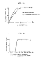
- Fig. 17 is a graph relating to this tenth preferred embodiment set in which average particle size in mesh of the alloy powder is shown along the horizontal axis and the above defined alloying rate A in percent is shown along the vertical axis. From this graph it will be understood that, in this case that as alloy powder is used a mixture of a silicon powder and a stellite powder, it is preferable for the average particle size of the silicon powder included in the alloy powder to be no more than about -24 mesh, more preferably no more than about -32 mesh, and even more preferably no more than about -42 mesh. And it should be noted that, in the cases that the average particle size of the silicon powder included in the alloy powder was greater than or equal to about -10 mesh, it was not possible satisfactorily to dispose the alloying powder on the surface of the substrate aluminum alloy blocks.
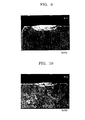
- Figs. 18 and 19 are cross sectional optical photomicrograph views at enlargements of 100X taken transversely through the bead portions produced by those two ones of this tenth set of preferred embodiments of the present invention alloy layer forming method in which the average size of the silicon powder included in the alloy powder was about -16 mesh, and was about -325 mesh, respectively.
- the average size of the silicon powder included in the alloy powder was about -16 mesh, from this sectional view it will be understood that, if surface alloying is performed according to this one of the tenth set of preferred embodiments, the alloy layer had a large number of defects such as blow holes, and was not satisfactory; this is thought to have been due to inclusion of gas in the alloy layer.
- the alloy layer had no substantial defects such as blow holes, and had a satisfactory and substantially uniform composition.
- another set of nine quantities of alloy powder was produced by using quantities of a silicon - copper alloy (composition about 50% silicon, remainder substantially copper) which had been ground into powder of nine different average particle sizes (unit mesh), to wit: approximately -35 mesh, approximately -5 mesh, approximately -10 mesh, approximately -16 mesh, approximately -24 mesh, approximately -50 mesh, approximately -150 mesh, approximately -250 mesh, and approximately -325 mesh.
- nine substrate material test sample pieces were prepared, each of substantially the same dimensions of approximately 70 mm x 40 mm x 10 mm as in the case of the previously described preferred embodiments, and again being made of substantially the same type of aluminum alloy of JIS (Japanese Industrial Standard) ADC-10.
- an alloy layer bead was formed in substantially the same manner as in the first preferred embodiment disclosed above, the parameters of this laser fusing process being substantially as in the case of said first preferred embodiment.
- the alloying rate A (in percent) for each of the nine cases was again determined according to the formula described above; and the results of these tests were found to be generally similar to those detailed above with regard to the tenth preferred embodiment and shown in Fig. 17.
- bismuth powder is used for admixture with the alloy material. This is the second of the two materials that have been found by the present inventors to be suitable for this application.
- FIG. 1 through 4 can serve for describing said stages of said eleventh preferred embodiment set, since said eleventh preferred embodiment set does not differ in outward appearance from the first preferred embodiment set, but only by the materials utilized and by certain process parameters.
- a first quantity designated as "A" of alloy powder was produced by evenly combining together in a weight ratio of approximately 1:1 a quantity of bismuth powder of average particle size approximately -100 mesh and a quantity of stellite alloy powder (composition approximately 24% approximately 0.5% silicon, approximately 0.1% boron, not more than 0.4% carbon, and remainder substantially cobalt) of average particle size approximately -100 mesh.
- a second quantity designated as "B” of alloy powder was produced by evenly combining together in a weight ratio of approximately 1:1 a quantity of bismuth powder of average particle size approximately -250 mesh and a quantity of similarly composed stellite alloy powder of average particle size approximately -100 mesh.
- alloy powder quantities "A” and "B” were, as will be seen, constituted so as to be suitable for practice of the two preferred embodiments of the method of the present invention included in the eleventh set thereof. And for the practice of a comparison method, not according to the present invention, there was produced a quantity designated as "C" of a third powder, being similarly composed stellite powder only, of average particle size approximately -100 mesh. And, next, to each of these powders for alloying there was added a quantity of 5% aqueous solution of polyvinyl alcohol, to serve as a binder, and thus in each of the three cases there was formed a paste with a viscosity higher than that of water and lower than that of clay.
- substrate material test sample pieces 1 of the same type as described before were prepared, each being a cuboidal block with dimensions approximately 70 mm x 40 mm x 10 mm, and being made of aluminum alloy of JIS (Japanese Industrial Standard) ADC-10. And, as shown in the side perspective view of Fig. 1 which shows the first stage of practice of these eleventh set of preferred embodiments, on each of the 70 mm x 40 mm surfaces denoted as la of three of these four aluminum alloy substrate material pieces 1 there were laid two guide plates 2 and 3 of suitable material, of thickness about 1 mm, with their longer edges parallel to and confronting one another and separated by about 5 mm.
- JIS Japanese Industrial Standard
- each of the assemblies as shown in Fig. was heated to a temperature of about 100 C in a drying oven and was maintained at said temperature for about one hour; thus in each case the alloy powder paste quantity 4 was thoroughly dried. Then, in each case, the two guide plates 2 and 3 were removed, to leave as shown in Fig. 2 in perspective view the block 1 of aluminum alloy substrate material with a strip layer 5 of the corresponding alloy powder laid along its 70 mm x 40 mm surface la parallel to and midway between the long sides thereof, said strip layer 5 being bound together and congealed to the block 1 by the hardened binder.
- said strip layer 5 had width about 5 mm, thickness about 1.0 mm, and length about 60 mm. Further, on the 70 mm x 40 mm surface la of the fourth aluminum alloy substrate material piece 1 there was laid, parallel to and midway between the long sides thereof, a strip piece designated as "D" made of so called D-6k alloy material (composition approximately 30% chromium, approximately 4.5% tungsten, approximately 1.0% carbon, and remainder substantially cobalt), of dimensions width about 5 mm, thickness about 0.5 mm, and length about 60 mm.
- D D-6k alloy material
- a C0 2 laser gun 6 was scanned in one pass along each of these strips 5 of material (either congealed alloy powder or strip material) for being alloyed with the substrate aluminum alloy block 1, from one end thereof to the other, while simultaneously a stream of argon gas was emitted from the end of said laser gun 6, said argon gas stream acting as a shield gas.
- the laser gun 6 was at this time operated so as to emit laser radiation, denoted in Fig. 3 as 7, and this process caused local heating of the strip 5 of material for alloying, and melting thereof.
- the laser output was about 2.0 kilowatts; the output mode was multi mode; the beam pattern was elliptical, with the long diameter about 5 mm and the short diameter about 3.5 mm; the laser scanning speed was about 300 mm per minute; and the flow rate of the argon shield gas was about 35 liters per minute.
- a bead portion 8 of fused and melted together alloy material (powder or strip) and substrate aluminum alloy material was formed along the 70 mm x 40 mm surface la of each substrate material block 1, parallel to and midway between the long sides thereof. During this process, the molten portion was cooled rapidly, principally by absorption of the heat therein by the main body of the substrate material block 1.
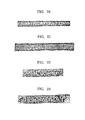
- Figs. 20 through 23 are plan views showing the bead portions 8 (i.e., the alloy layers) formed in each of the four cases described above, by employing the alloy materials "A", “B", “C”, and “D” respectively; thus, Figs. 20 and 21 were made according to the two preferred embodiments included in the eleventh set of preferred embodiments of the alloy layer forming method of the present invention, by utilizing bismuth powder mixed in with the stellite alloy material powder, while Figs. 22 and 23 were made by comparison methods not according to the present invention (which in fact correspond to the comparison methods detailed with regard to the first set of preferred embodiments detailed earlier). Further, Figs.
- the alloy layer bead portion 8 was about 1.8 mm by about 4.2 mm in cross sectional dimensions, had surface hardness about 350 to 450, and had good surface appearance; in the case of the second one of said eleventh set of preferred embodiments of the present invention which utilized the powder alloy material "B”, the alloy layer bead portion 8 was about 1.6 mm by about 4.0 mm in cross sectional dimensions, had surface hardness about 150 to 200, and likewise had good surface appearance; in the case of the first comparison method which utilized the powder alloy material "C” which contained only stellite powder but contained substantially no bismuth powder, the alloy layer bead portion 8 was not properly formed, ins
- alloy powder material "B” made using the alloy powder material "B" was analyzed; and the composition thereof was found to be approximately 10% chromium, approximately 1.0% tungsten, approximately 3.5% nickel, approximately 3.0% silicon, approximately 0.05% boron, approximately 0.05% carbon, approximately 20% bismuth, approximately 7.5% cobalt, and remainder substantially aluminum.
- the laser fusing step performed during the practice of the twelfth preferred embodiment of the method for forming an alloy layer on a substrate of the present invention is substantially the same as described above with reference to the second preferred embodiment and shown in side view in Fig. 11; accordingly, this Fig. 11 will be used for explanation of this - twelfth preferred embodiment, also, which differs from the second preferred embodiment only in the materials used and in certain process parameters.
- this twelfth preferred embodiment was performed as follows.
- a quantity of alloy powder was produced by powdering to approximately -100 mesh a quantity of bismuth - copper alloy (composition approximately 80% copper, and remainder substantially bismuth).
- a substrate material test sample piece 9 was prepared, of substantially the same dimensions of approximately 70 mm x 40 mm x 10 mm as in the case of the eleventh set of preferred embodiments, and being made of substantially the same type of aluminum alloy of JIS (Japanese Industrial Standard) ADC-10.
- a C0 2 laser gun 10 was scanned in one pass along this substrate aluminum alloy block 9, from one end thereof to the other along the central portion of a 70 x 40 mm face 9a thereof and parallel to the 70 mm long sides of said face 9a, while simultaneously a stream of argon gas was emitted from the end of said laser gun 10, said argon gas stream acting as a shield gas; and, further, onto said upper face 9a of said alloy block 9 just into the path of said laser gun 10 and before it there was fed a steady stream of the above described alloy powder, a mass 12 of which was held in a hopper 11 a lower portion of which opened into an intermediate position along a downwardly sloping pipe 13 from which said alloy powder stream thus sifted and emerged, along with another admixture stream of argon gas which further was fed through said pipe 13 as a carrier gas.
- the laser gun 10 was at this time operated so as to emit laser radiation, denoted in Fig. 11 as 15, and this process caused local heating of the upper surface of the alloy block 9 and of the alloy powder just laid thereon, for fusingly alloying and melting thereof into a molten alloy layer 14 in the path of under and behind the laser gun 10, and said molten alloy layer hardened into a bead 16 trailing behind the laser gun 10.
- the laser gun output was about 2.0 kilowatts
- the output mode was multi mode
- the beam pattern was elliptical, with the long diameter about 5 mm and the short diameter about 3.5 mm
- the laser gun scanning speed was about 300 mm per minute
- the flow rate of the argon shield gas was about 35 liters per minute.
- Fig.26 is a cross sectional optical photomicrograph view at an enlargement of 10X taken transversely through the bead portion 16 produced by said twelfth preferred embodiment of the present invention alloy layer forming method.
- the portions showing up as black islands or specks of black color in the alloy layer are portions which are agglomerations of metallic compounds formed between copper and bismuth, while the portions which show up as dark gray are those with a relatively high concentration of bismuth.
- a central portion of the bead portion 16 illustrated in Fig. 26 was analyzed; and the composition thereof was found to be approximately 27.5% copper, approximately 75% bismuth, and remainder substantially aluminum.
- the thirteenth preferred embodiment of the method for forming an alloy layer on a substrate of the present invention was performed as follows. Initially, a quantity of alloy powder was produced by powdering to approximately -48 mesh a quantity of bismuth - nickel alloy (composition approximately 20% nickel, and remainder substantially bismuth). And a substrate material test sample piece was prepared, of substantially the same dimensions of approximately 70 mm x 40 mm x 10 mm as in the case of the eleventh set of preferred embodiments and the twelfth preferred embodiment, and again being made of substantially the same type of aluminum alloy of JIS (Japanese Industrial Standard) ADC-10.
- JIS Japanese Industrial Standard
- an alloy layer bead was formed in substantially the same manner as in the twelfth preferred embodiment disclosed above, i.e. by scanning a CO 2 laser gun in one pass along an upper face of this substrate aluminum alloy block while simultaneously feeding a steady stream of the above described alloy powder onto said upper face of said alloy block just into the path of said laser gun, with the laser gun being operated so as to emit laser radiation and so as to cause local heating of the upper surface of the alloy block and of the alloy powder just laid thereon for fusingly alloying and melting thereof into a molten alloy layer in the path of under and behind the laser gun, said molten alloy layer hardening into a bead trailing behind the laser gun.
- the parameters of this laser fusing process were substantially as in the case of the twelfth preferred embodiment described above.
- Fig.27 is a cross sectional optical photomicrograph view at an enlargement of 10X taken transversely through the bead portion produced by this thirteenth preferred embodiment of the present invention alloy layer forming method.
- the external appearance and tidyness of the bead is of good quality, and again an alloy layer with no substantial defects such as blow holes can be formed on the surface of the aluminum alloy substrate block.
- the portions showing up as islands of black color in the alloy layer are agglomerations of metallic compounds formed between nickel and bismuth, and the dark gray portions are portions where the concentration of bismuth is relatively high.
- a central portion of the bead portion 16 illustrated in Fig. 27 was analyzed; and the composition thereof was found to be approximately 20% nickel, approximately 75% bismuth, and remainder substantially aluminum.
- the fourteenth set of preferred embodiments of the method for forming an alloy layer on a substrate of the present invention were performed as follows. Initially, a set of seven quantities of alloy powder was produced by combining together in seven different weight ratios quantities of bismuth powder the same as used in the eleventh set of preferred embodiments (of average particle size approximately -250 mesh) and quantities of stellite alloy powder also the same as used in said eleventh set of preferred embodiments. The bismuth contents of these seven alloy powder quantities were respectively approximately 2%, approximately 12%, approximately 31%, approximately 50%, approximately 70%, approximately 89%, and approximately 97%.
- substrate material test sample pieces were prepared, each of substantially the same dimensions of approximately 70 mm x 40 mm x 10 mm as in the case of the previously described preferred embodiments, and again being made of substantially the same type of aluminum alloy of JIS (Japanese Industrial Standard) ADC-10.
- an alloy layer bead was formed in substantially the same manner as in the eleventh preferred embodiment set disclosed above, i.e. by laying a strip of the particular alloy powder along along an upper face of one of the substrate aluminum alloy blocks, said strip being congealed together and stuck to said substrate block upper face by the use of binder and by scanning a CO 2 laser gun along said alloy powder strip, with the laser gun being operated so as to emit laser radiation and so as to cause local heating of the upper surface of the alloy block and of the alloy powder strip laid thereon for fusingly alloying and melting thereof into a molten alloy layer in the path of under and behind the laser gun, said molten alloy layer hardening into a bead trailing behind the laser gun.
- the parameters of this laser fusing process were substantially as in the case of the eleventh preferred embodiment set described above.
- the alloying rate A (in percent) for each of the seven cases was then determined according to the formula explained above with regard to the fourth preferred embodiment set.
- Fig. 28 is a graph in which bismuth content in percent of the alloy powder is shown along the horizontal axis and the above defined alloying rate A in percent is shown along the vertical axis. From this graph it will be understood that, in this case that as alloy powder is used a mixture of a bismuth powder and a stellite alloy powder, it is preferable for the bismuth content of the alloy powder to be at least 21%; that particularly, in this case, in order for the method according to the present invention to form properly an appropriate alloy layer said alloy powder bismuth content should be at least 35%; and that even more preferably said bismuth content should be at least 41%.
- the fifteenth set of preferred embodiments of the method for forming an alloy layer on a substrate of the present invention were performed as follows. Initially, a set of seven quantities of alloy powder was produced by combining together in seven different weight ratios quantities of bismuth and quantities of stellite alloy, by fusing said bismuth and stellite alloy together so as to alloy them together, and then by powdering the resulting alloy to an average particle size of approximately -100 mesh.
- the bismuth contents of these seven alloy powder quantities were respectively approximately 2%, approximately 10%, approximately 32%, approximately 40%, approximately 71%, approximately 90%, and approximately 98%.
- substrate material test sample pieces were prepared, each of substantially the same dimensions of approximately 70 mm x 40 mm x 10 mm as in the case of the previously described preferred embodiments, and again being made of substantially the same type of aluminum alloy of JIS (Japanese Industrial Standard) ADC-10.
- an alloy layer bead was formed in substantially the same manner as in the first preferred embodiment disclosed above, i.e. by laying a strip of the particular alloy powder along along an upper face of one of the substrate aluminum alloy blocks, said strip being congealed together and stuck to said substrate block upper face by the use of binder and by scanning a CO 2 laser gun along said alloy powder strip, with the laser gun being operated so as to emit laser radiation and so as to cause local heating of the upper surface of the alloy block and of the alloy powder strip laid thereon for fusingly alloying and melting thereof into a molten alloy layer in the path of under and behind the laser gun, said molten alloy layer hardening into a bead trailing behind the laser gun.
- the parameters of this laser fusing process were substantially as in the case of the eleventh preferred embodiment described above.
- the alloying rate A (in percent) for each of the seven cases was then determined according to the formula described above.
- the results of these tests are shown by the seven light spots and the line drawn with reference thereto in the Fig. 28 graph. From this graph it will be understood that, in this case that as alloy powder is used a powdered form of a fused alloy of bismuth and a stellite alloy, it is preferable for the bismuth content of the alloy powder to be at least 15%; that particularly, in this case, in order for the method according to the present invention to form properly an appropriate alloy layer said alloy powder bismuth content should be at least 28%; and that even more preferably said bismuth content should be at least 32%.
- the sixteenth set of preferred embodiments of the method for forming an alloy layer on a substrate of the present invention were performed as follows. Initially, a set of nine quantities of alloy powder was produced by combining together in nine different weight ratios quantities of bismuth powder the same as used in the eleventh set of preferred embodiments (of average particle size approximately -250 mesh) and quantities of copper alloy powder having an average particle size approximately -100 mesh. The bismuth contents of these nine alloy powder quantities were respectively approximately 2%, approximately 10%, approximately 21%, approximately 31%, approximately 41%, approximately 51%, approximately 69%, approximately 89%, and approximately 97%.
- Fig. 29 is a graph similar to the Fig.28 graph for the fourteenth and the fifteenth sets of preferred embodiments and relating to this sixteenth preferred embodiment set and to the seventeenth preferred embodiment set to be described shortly, in which again bismuth content in percent of the alloy powder is shown along the horizontal axis and the above defined alloying rate A in percent is shown along the vertical axis. From this graph it will be understood that, in this case that as alloy powder is used a mixture of a bismuth powder and a copper powder, it is preferable for the bismuth content of the alloy powder to be at least 13%; and that particularly said bismuth content should preferably be at least 29%.
- the seventeenth set of preferred embodiments of the method for forming an alloy layer on a substrate of the present invention were performed as follows. Initially, a set of nine quantities of alloy powder was produced by combining together in nine different weight ratios quantities of bismuth and quantities of copper, by fusing said bismuth and copper together so as to alloy them together, and then by powdering the resulting alloy to an average particle size of approximately -100 mesh.
- the bismuth contents of these nine alloy powder quantities were respectively approximately 2%, approximately 10%, approximately 21%, approximately 31%, approximately 41%, approximately 50%, approximately 70%, approximately 90%, and approximately 98%.
- the results of these tests are shown by the nine light spots and the line drawn with reference thereto in the Fig. 29 graph. From this graph it will be understood that, in this case that as alloy powder is used a powdered form of a fused alloy of bismuth and copper, it is preferable for the bismuth content of the alloy powder to be at least 4%; and that particularly, in this case, in order for the method according to the present invention to form properly an appropriate alloy layer, said alloy powder bismuth content should be at least 10%.
- alloy powder was used either a mixture of a bismuth powder and a copper powder or a powdered form of a fused alloy of bismuth and copper
- the alloying rate was 100% or a high value relatively close to 100%; and it is surmised that this is due to the high solid solubility of copper in aluminum alloy.
- the eighteenth set of preferred embodiments of the method for forming an alloy layer on a substrate of the present invention were performed as follows. Initially, a set of seven quantities of alloy powder was produced by combining together in seven different weight ratios quantities of bismuth powder the same as used in the eleventh set of preferred embodiments (of average particle size approximately -250 mesh) and quantities of nickel alloy powder having an average particle size approximately -100 mesh. The bismuth contents of these seven alloy powder quantities were respectively approximately 2%, approximately 12%, approximately 32%, approximately 50%, approximately 70%, approximately 90%, and approximately 97%.
- substrate material test sample pieces were prepared, each of substantially the same dimensions of approximately 70 mm x 40 mm x 10 mm as in the case of the previously described preferred embodiments, and again being made of substantially the same type of aluminum alloy of JIS (Japanese Industrial Standard) ADC-10. And, in each of the seven cases, an alloy layer bead was formed in substantially the same manner as in the eleventh preferred embodiment disclosed above, i.e.
- Fig. 30 is a graph similar to the Fig. 28 and Fig. 29 graphs for the fourteenth through the seventeenth sets of preferred embodiments and relating to this eighteenth preferred embodiment set and to the nineteenth preferred embodiment set to be described shortly, in which again bismuth content in percent of the alloy powder is shown along the horizontal axis and the above defined alloying rate A in percent is shown along the vertical axis.
- the bismuth content of the alloy powder is at least 21%; that particularly, in this case, in order for the method according to the present invention to form properly an appropriate alloy layer said alloy powder bismuth content should be at least 35%; and that even more preferably said bismuth content should be at least 41%.
- the nineteenth set of preferred embodiments of the method for forming an alloy layer on a substrate of the present invention were performed as follows. Initially, a set of seven quantities of alloy powder was produced by combining together in seven different weight ratios quantities of bismuth and quantities of nickel, by fusing said bismuth and nickel together so as to alloy them together, and then by powdering the resulting alloy to an average particle size of approximately -100 mesh. The bismuth contents of these seven alloy powder quantities were respectively approximately 2%, approximately 10%, approximately 21%, approximately 41%, approximately 71%, approximately 91%, and approximately 98%.
- substrate material test sample pieces were prepared, each again of substantially the same dimensions of approximately 70 mm x 40 mm x 10 mm as in the case of the previously described preferred embodiments, and again being made of substantially the same type of aluminum alloy of JIS (Japanese Industrial Standard) ADC-10. And, in each of the seven cases, an alloy layer bead was formed in substantially the same manner as in the eleventh preferred embodiment disclosed above, i.e.
- the results of these tests are shown by the seven light spots and the line drawn with reference thereto in the Fig. 30 graph. From this graph it will be understood that, in this case that as alloy powder is used a powdered form of a fused alloy of bismuth and nickel, it is preferable for the bismuth content of the alloy powder to be at least 15%; that particularly, in this case, in order for the method according to the present invention to form properly an appropriate alloy layer said alloy powder bismuth content should be at least 28%; and that even more preferably said bismuth content should be at least 32%.
- the bismuth content of the alloy powder in the case that as alloy powder is used a powder mixture of a bismuth powder and a powder of an element to be alloyed with the aluminum alloy substrate block, it is preferable for the bismuth content of the alloy powder to be at least 21%, more preferably at least 35%, and even more preferably at least 41%; while, in the alternative case that as alloy powder is used a powdered form of a fused alloy of bismuth and said element to be alloyed with said aluminum alloy substrate block, it is preferable for the bismuth content of the alloy powder to be at least 15%, more preferably at least 28%, and even more preferably at least 32%.
- the twentieth set of preferred embodiments of the method for forming an alloy layer on a substrate of the present invention were performed as follows. Initially, a set of nine quantities of alloy powder was produced by combining together, in each case in a weight ratio of approximately 1:1, quantities of stellite alloy powder of the type used in the eleventh set of preferred embodiments described above and having an average particle size approximately -100 mesh, and quantities of bismuth powder of nine different average particle sizes, to wit: approximately -3.5 mesh, approximately -5 mesh, approximately -10 mesh, approximately -42 mesh, approximately -48 mesh, approximately -60 mesh, approximately -150 mesh, approximately -250 mesh, and approximately -325 mesh.
- Fig. 31 is a graph relating to this twentieth preferred embodiment set in which average particle size in mesh of the alloy powder is shown along the horizontal axis and the above defined alloying rate A in percent is shown along the vertical axis. From this graph it will be understood that, in this case that as alloy powder is used a mixture of a bismuth powder and a stellite powder, it is preferable for the average particle size of the bismuth powder included in the alloy powder to be no more than about -42 mesh, more preferably no more than about -48 mesh, and even more preferably from about -55 mesh to about -325 mesh. And it should be noted that, in the cases that the average particle size of the bismuth powder included in the alloy powder was greater than or equal to about -10 mesh, it was not possible satisfactorily to dispose the alloying powder on the surface of the substrate aluminum alloy blocks.
- another set of nine quantities of alloy powder was produced by using quantities of a bismuth - copper alloy (composition about 50% bismuth, remainder substantially copper) which had been ground into powder of nine different average particle sizes (unit mesh), to wit: approximately -35 mesh, approximately -5 mesh, approximately -10 mesh, approximately -42 mesh, approximately -48 mesh, approximately -60 mesh, approximately -150 mesh, approximately -250 mesh, and approximately -325 mesh.
- nine substrate material test sample pieces were prepared, each of substantially the same dimensions of approximately 70 mm x 40 mm x 10 mm as in the case of the previously described preferred embodiments, and again being made of substantially the same type of aluminum alloy of JIS (Japanese Industrial Standard) ADC-10.
- an alloy layer bead was formed in substantially the same manner as in the eleventh preferred embodiment disclosed above, the parameters of this laser fusing process being substantially as in the case of said eleventh preferred embodiment.
- the alloying rate A (in percent) for each of the nine cases was again determined according to the formula described above; and the results of these tests were found to be generally similar to those detailed above with regard to the twentieth preferred embodiment and shown in Fig. 31.
Landscapes
- Engineering & Computer Science (AREA)
- Mechanical Engineering (AREA)
- Other Surface Treatments For Metallic Materials (AREA)
- Powder Metallurgy (AREA)
Applications Claiming Priority (4)
| Application Number | Priority Date | Filing Date | Title |
|---|---|---|---|
| JP60178430A JPS6238789A (ja) | 1985-08-13 | 1985-08-13 | Co↓2レ−ザによる合金層の形成方法 |
| JP60178431A JPS6238790A (ja) | 1985-08-13 | 1985-08-13 | Co↓2レ−ザによる合金層の形成方法 |
| JP178431/85 | 1985-08-13 | ||
| JP178430/85 | 1985-08-13 |
Publications (3)
| Publication Number | Publication Date |
|---|---|
| EP0212938A2 true EP0212938A2 (de) | 1987-03-04 |
| EP0212938A3 EP0212938A3 (en) | 1989-07-12 |
| EP0212938B1 EP0212938B1 (de) | 1992-03-18 |
Family
ID=26498606
Family Applications (1)
| Application Number | Title | Priority Date | Filing Date |
|---|---|---|---|
| EP86306245A Expired EP0212938B1 (de) | 1985-08-13 | 1986-08-13 | Verfahren zur Erzeugung einer Legierungsschicht auf einem Aluminiumlegierungssubstrat durch Auftragen eines ein Legierungsbestandteil und Wismut enthaltendes Pulver und Bestrahlung mit einem CO2-Laser |
Country Status (5)
| Country | Link |
|---|---|
| US (1) | US4746540A (de) |
| EP (1) | EP0212938B1 (de) |
| AU (1) | AU582886B2 (de) |
| CA (1) | CA1265393A (de) |
| DE (1) | DE3684382D1 (de) |
Cited By (4)
| Publication number | Priority date | Publication date | Assignee | Title |
|---|---|---|---|---|
| EP0488944A1 (de) * | 1990-11-28 | 1992-06-03 | ALUSUISSE-LONZA SERVICES Ltd. | Verfahren zum Anodisieren von ALSi-Legierungen |
| US5182430A (en) * | 1990-10-10 | 1993-01-26 | Societe National D'etude Et De Construction De Moteurs D'aviation "S.N.E.C.M.A." | Powder supply device for the formation of coatings by laser beam treatment |
| WO1997004914A1 (en) * | 1995-07-28 | 1997-02-13 | Commonwealth Scientific And Industrial Research Organisation | Pulsed laser cladding arrangement |
| CN104507601A (zh) * | 2012-05-28 | 2015-04-08 | 瑞尼斯豪公司 | 金属制品的制造 |
Families Citing this family (28)
| Publication number | Priority date | Publication date | Assignee | Title |
|---|---|---|---|---|
| JPS6216894A (ja) * | 1985-07-17 | 1987-01-26 | Toyota Motor Corp | アルミニウム系母材への肉盛方法 |
| JPS6254588A (ja) * | 1985-08-30 | 1987-03-10 | Toyota Motor Corp | セラミツク粒子分散アルミニウム合金複合層の形成方法 |
| JPH0698506B2 (ja) * | 1986-12-08 | 1994-12-07 | トヨタ自動車株式会社 | 金属基体上への分散合金層の形成方法 |
| US5132083A (en) * | 1986-12-15 | 1992-07-21 | Kabushiki Kaisha Komatsu Seisakusho | Laser padding material and a laser padding method using the same |
| LU86753A1 (fr) * | 1987-01-30 | 1988-08-23 | Centre Rech Metallurgique | Procede pour le traitement superficiel d'un cylindre de laminoir |
| DE3922378A1 (de) * | 1989-07-07 | 1991-01-17 | Audi Ag | Verfahren zum herstellung verschleissfester oberflaechen an bauteilen aus einer aluminium-silicium-legierung |
| US5653897A (en) * | 1993-02-17 | 1997-08-05 | Electric Power Research Institute | Rotating fiber optic coupler for high power laser welding applications |
| US5430270A (en) * | 1993-02-17 | 1995-07-04 | Electric Power Research Institute, Inc. | Method and apparatus for repairing damaged tubes |
| US5514849A (en) * | 1993-02-17 | 1996-05-07 | Electric Power Research Institute, Inc. | Rotating apparatus for repairing damaged tubes |
| US5665255A (en) * | 1995-08-01 | 1997-09-09 | Progressive Tool & Industries Company | Laser welding apparatus and method for high temperature gradient cooling alloys |
| US6350326B1 (en) | 1996-01-15 | 2002-02-26 | The University Of Tennessee Research Corporation | Method for practicing a feedback controlled laser induced surface modification |
| US6294225B1 (en) | 1999-05-10 | 2001-09-25 | The University Of Tennessee Research Corporation | Method for improving the wear and corrosion resistance of material transport trailer surfaces |
| US6299707B1 (en) | 1999-05-24 | 2001-10-09 | The University Of Tennessee Research Corporation | Method for increasing the wear resistance in an aluminum cylinder bore |
| US6173886B1 (en) | 1999-05-24 | 2001-01-16 | The University Of Tennessee Research Corportion | Method for joining dissimilar metals or alloys |
| US6497985B2 (en) | 1999-06-09 | 2002-12-24 | University Of Tennessee Research Corporation | Method for marking steel and aluminum alloys |
| US6284067B1 (en) | 1999-07-02 | 2001-09-04 | The University Of Tennessee Research Corporation | Method for producing alloyed bands or strips on pistons for internal combustion engines |
| US6423162B1 (en) | 1999-07-02 | 2002-07-23 | The University Of Tennesse Research Corporation | Method for producing decorative appearing bumper surfaces |
| DE19934856A1 (de) * | 1999-07-24 | 2001-01-25 | Abb Research Ltd | Turbinenschaufel und Verfahren zu deren Herstellung |
| US6328026B1 (en) | 1999-10-13 | 2001-12-11 | The University Of Tennessee Research Corporation | Method for increasing wear resistance in an engine cylinder bore and improved automotive engine |
| US6229111B1 (en) | 1999-10-13 | 2001-05-08 | The University Of Tennessee Research Corporation | Method for laser/plasma surface alloying |
| DE10124250C2 (de) * | 2001-05-18 | 2003-03-27 | Daimler Chrysler Ag | Verfahren zur Bildung einer hochfesten und verschleißbeständigen Verbundschicht |
| DE60334826D1 (de) * | 2002-09-30 | 2010-12-16 | Welding Inst Abington | Verfahren zur werkstückstrukturmodifikation |
| DE502005009857D1 (de) * | 2004-01-28 | 2010-08-19 | Ford Global Tech Llc | Durch thermisches spritzen aufgebrachte eisenhaltige schicht einer gleitfläche, insbesondere für zylinderlaufflächen von motorblöcken |
| FI119923B (fi) * | 2005-09-08 | 2009-05-15 | Kemppi Oy | Menetelmä ja laitteisto lyhytkaarihitsausta varten |
| US20090181078A1 (en) * | 2006-09-26 | 2009-07-16 | Infectious Disease Research Institute | Vaccine composition containing synthetic adjuvant |
| SE532457C2 (sv) * | 2008-07-03 | 2010-01-26 | Esab Ab | Pulverhanteringsanordning för svetsning under pulver |
| CN103451650A (zh) * | 2013-10-08 | 2013-12-18 | 岳阳大陆激光技术有限公司 | 一种大型旋转机械轴瓦激光快速修复工艺方法 |
| CN103611927B (zh) * | 2013-11-20 | 2015-12-30 | 柳岸敏 | 专用于连续波光纤激光熔覆的钴基金属陶瓷合金粉末 |
Family Cites Families (15)
| Publication number | Priority date | Publication date | Assignee | Title |
|---|---|---|---|---|
| US3285717A (en) * | 1964-08-10 | 1966-11-15 | Aluminum Co Of America | Composite aluminum article and aluminum alloys |
| DE2200003B2 (de) * | 1972-01-03 | 1977-09-15 | Karl Schmidt Gmbh, 7107 Neckarsulm | Verfahren zur oberflaechenverguetung von leichtmetallkolben |
| US4401726A (en) * | 1974-01-07 | 1983-08-30 | Avco Everett Research Laboratory, Inc. | Metal surface modification |
| US4074616A (en) * | 1975-09-02 | 1978-02-21 | Caterpillar Tractor Co. | Aluminum piston with steel reinforced piston ring grooves |
| US4157923A (en) * | 1976-09-13 | 1979-06-12 | Ford Motor Company | Surface alloying and heat treating processes |
| US4212900A (en) * | 1978-08-14 | 1980-07-15 | Serlin Richard A | Surface alloying method and apparatus using high energy beam |
| US4382169A (en) * | 1981-03-24 | 1983-05-03 | Rabkin Daniil M | Weld deposition of metal other than aluminium onto aluminium-base alloy |
| WO1982003814A1 (en) * | 1981-04-28 | 1982-11-11 | Plc Ae | Piston manufacture |
| US4432313A (en) * | 1982-05-27 | 1984-02-21 | Trw Inc. | Aluminum base material with hard facing deposit |
| US4451302A (en) * | 1982-08-27 | 1984-05-29 | Aluminum Company Of America | Aluminum nitriding by laser |
| EP0117352A1 (de) * | 1983-02-24 | 1984-09-05 | Fujitsu Limited | Verfahren zum Schweissen von Bauteilen auf der Basis von Aluminium und geschweisster Aufbau |
| JPS59219468A (ja) * | 1983-05-25 | 1984-12-10 | Teikoku Piston Ring Co Ltd | アルミニウム製摺動部材及びその製造方法 |
| JPS6216894A (ja) * | 1985-07-17 | 1987-01-26 | Toyota Motor Corp | アルミニウム系母材への肉盛方法 |
| AU6109586A (en) * | 1985-08-13 | 1987-02-19 | Toyota Jidosha Kabushiki Kaisha | Alloy layer on al-alloy substrate using co2 laser |
| JPS6254588A (ja) * | 1985-08-30 | 1987-03-10 | Toyota Motor Corp | セラミツク粒子分散アルミニウム合金複合層の形成方法 |
-
1986
- 1986-08-08 US US06/894,941 patent/US4746540A/en not_active Expired - Fee Related
- 1986-08-12 AU AU61078/86A patent/AU582886B2/en not_active Ceased
- 1986-08-12 CA CA000515757A patent/CA1265393A/en not_active Expired
- 1986-08-13 EP EP86306245A patent/EP0212938B1/de not_active Expired
- 1986-08-13 DE DE8686306245T patent/DE3684382D1/de not_active Expired - Lifetime
Cited By (5)
| Publication number | Priority date | Publication date | Assignee | Title |
|---|---|---|---|---|
| US5182430A (en) * | 1990-10-10 | 1993-01-26 | Societe National D'etude Et De Construction De Moteurs D'aviation "S.N.E.C.M.A." | Powder supply device for the formation of coatings by laser beam treatment |
| EP0488944A1 (de) * | 1990-11-28 | 1992-06-03 | ALUSUISSE-LONZA SERVICES Ltd. | Verfahren zum Anodisieren von ALSi-Legierungen |
| CH682327A5 (de) * | 1990-11-28 | 1993-08-31 | Alusuisse Lonza Services Ag | |
| WO1997004914A1 (en) * | 1995-07-28 | 1997-02-13 | Commonwealth Scientific And Industrial Research Organisation | Pulsed laser cladding arrangement |
| CN104507601A (zh) * | 2012-05-28 | 2015-04-08 | 瑞尼斯豪公司 | 金属制品的制造 |
Also Published As
| Publication number | Publication date |
|---|---|
| EP0212938A3 (en) | 1989-07-12 |
| US4746540A (en) | 1988-05-24 |
| AU582886B2 (en) | 1989-04-13 |
| DE3684382D1 (de) | 1992-04-23 |
| AU6107886A (en) | 1987-02-19 |
| CA1265393A (en) | 1990-02-06 |
| EP0212938B1 (de) | 1992-03-18 |
Similar Documents
| Publication | Publication Date | Title |
|---|---|---|
| EP0212938A2 (de) | Verfahren zur Erzeugung einer Legierungsschicht auf einem Aluminiumlegierungssubstrat durch Auftragen eines ein Legierungsbestandteil und Wismut enthaltendes Pulver und Bestrahlung mit einem CO2-Laser | |
| EP0221276B1 (de) | Verfahren zur Ausbildung einer Verbundschicht durch Laserbestrahlung der Oberfläche eines Substrats einer Aluminiumlegierung | |
| EP3590642B1 (de) | Verschleissfeste legierungszusammensetzungen auf eisenbasis, die chrom enthalten | |
| Zhong et al. | Microstructural evolution in high power laser cladding of Stellite 6+ WC layers | |
| Gassmann | Laser cladding with (WC+ W2C)/Co–Cr–C and (WC+ W2C)/Ni–B–Si composites for enhanced abrasive wear resistance | |
| Pantelis et al. | Formation of wear resistant Al–SiC surface composite by laser melt–particle injection process | |
| US6968990B2 (en) | Fabrication and utilization of metallic powder prepared without melting | |
| US20150336219A1 (en) | Composite materials and methods for laser manufacturing and repair of metals | |
| EP0213498A2 (de) | Verfahren zur Erzeugung einer Legierungsschicht auf einem Aluminiumlegierungssubstrat durch Auftragen eines ein Legierungsbestandteil und Titan oder Mangan enthaltendes Pulver und Bestrahlung mit einem CO2-Laser | |
| US4929511A (en) | Low temperature aluminum based brazing alloys | |
| JP2678804B2 (ja) | 鉄合金基材上に純Cu肉盛層を形成する方法 | |
| Marshall et al. | Hard‐particle Reinforced Composite Solders Part 1: Microcharacterisation | |
| US7727462B2 (en) | Method for meltless manufacturing of rod, and its use as a welding rod | |
| DE102015113826A1 (de) | Verfahren zur Ausbildung von dispersionsverfestigten Legierungen | |
| EP0145933B1 (de) | Hartlöt-Legierungen für niedrige Temperaturen auf Aluminiumbasis | |
| DE3437983C1 (de) | Verfahren zum Aufbringen eines metallischen Schutzüberzuges auf ein metallisches Substrat | |
| US5132083A (en) | Laser padding material and a laser padding method using the same | |
| US4161207A (en) | Production of carbide laden consumables in a graphite mold | |
| US4838341A (en) | Production of low temperature aluminum based brazing alloys | |
| Matthews | Laser Fusing of Hardfacing Alloy Powders.(Retroactive Coverage) | |
| US6193930B1 (en) | Brazing alloy | |
| Mridha et al. | Effects of processing parameters on microstructures and properties of TIG melted surface layer of steel | |
| JPH11181563A (ja) | 表面硬化アルミニウム部材およびその製造方法 | |
| JPS6238790A (ja) | Co↓2レ−ザによる合金層の形成方法 | |
| JPS6238789A (ja) | Co↓2レ−ザによる合金層の形成方法 |
Legal Events
| Date | Code | Title | Description |
|---|---|---|---|
| PUAI | Public reference made under article 153(3) epc to a published international application that has entered the european phase |
Free format text: ORIGINAL CODE: 0009012 |
|
| AK | Designated contracting states |
Kind code of ref document: A2 Designated state(s): DE FR GB IT |
|
| PUAL | Search report despatched |
Free format text: ORIGINAL CODE: 0009013 |
|
| AK | Designated contracting states |
Kind code of ref document: A3 Designated state(s): DE FR GB IT |
|
| 17P | Request for examination filed |
Effective date: 19890808 |
|
| 17Q | First examination report despatched |
Effective date: 19901123 |
|
| GRAA | (expected) grant |
Free format text: ORIGINAL CODE: 0009210 |
|
| AK | Designated contracting states |
Kind code of ref document: B1 Designated state(s): DE FR GB IT |
|
| ET | Fr: translation filed | ||
| REF | Corresponds to: |
Ref document number: 3684382 Country of ref document: DE Date of ref document: 19920423 |
|
| ITF | It: translation for a ep patent filed | ||
| PLBE | No opposition filed within time limit |
Free format text: ORIGINAL CODE: 0009261 |
|
| STAA | Information on the status of an ep patent application or granted ep patent |
Free format text: STATUS: NO OPPOSITION FILED WITHIN TIME LIMIT |
|
| 26N | No opposition filed | ||
| PGFP | Annual fee paid to national office [announced via postgrant information from national office to epo] |
Ref country code: DE Payment date: 19930806 Year of fee payment: 8 |
|
| PGFP | Annual fee paid to national office [announced via postgrant information from national office to epo] |
Ref country code: GB Payment date: 19940804 Year of fee payment: 9 |
|
| PGFP | Annual fee paid to national office [announced via postgrant information from national office to epo] |
Ref country code: FR Payment date: 19940809 Year of fee payment: 9 |
|
| PG25 | Lapsed in a contracting state [announced via postgrant information from national office to epo] |
Ref country code: DE Effective date: 19950503 |
|
| PG25 | Lapsed in a contracting state [announced via postgrant information from national office to epo] |
Ref country code: GB Effective date: 19950813 |
|
| GBPC | Gb: european patent ceased through non-payment of renewal fee |
Effective date: 19950813 |
|
| PG25 | Lapsed in a contracting state [announced via postgrant information from national office to epo] |
Ref country code: FR Effective date: 19960430 |
|
| REG | Reference to a national code |
Ref country code: FR Ref legal event code: ST |
|
| PG25 | Lapsed in a contracting state [announced via postgrant information from national office to epo] |
Ref country code: IT Free format text: LAPSE BECAUSE OF NON-PAYMENT OF DUE FEES;WARNING: LAPSES OF ITALIAN PATENTS WITH EFFECTIVE DATE BEFORE 2007 MAY HAVE OCCURRED AT ANY TIME BEFORE 2007. THE CORRECT EFFECTIVE DATE MAY BE DIFFERENT FROM THE ONE RECORDED. Effective date: 20050813 |