EP0213250A1 - Procédé pour fixer des pièces et fixation suivant ce procédé - Google Patents
Procédé pour fixer des pièces et fixation suivant ce procédé Download PDFInfo
- Publication number
- EP0213250A1 EP0213250A1 EP85630128A EP85630128A EP0213250A1 EP 0213250 A1 EP0213250 A1 EP 0213250A1 EP 85630128 A EP85630128 A EP 85630128A EP 85630128 A EP85630128 A EP 85630128A EP 0213250 A1 EP0213250 A1 EP 0213250A1
- Authority
- EP
- European Patent Office
- Prior art keywords
- members
- connection
- deformation
- deformed
- connection according
- Prior art date
- Legal status (The legal status is an assumption and is not a legal conclusion. Google has not performed a legal analysis and makes no representation as to the accuracy of the status listed.)
- Withdrawn
Links
Images
Classifications
-
- A—HUMAN NECESSITIES
- A01—AGRICULTURE; FORESTRY; ANIMAL HUSBANDRY; HUNTING; TRAPPING; FISHING
- A01G—HORTICULTURE; CULTIVATION OF VEGETABLES, FLOWERS, RICE, FRUIT, VINES, HOPS OR SEAWEED; FORESTRY; WATERING
- A01G9/00—Cultivation in receptacles, forcing-frames or greenhouses; Edging for beds, lawn or the like
- A01G9/14—Greenhouses
- A01G9/1407—Greenhouses of flexible synthetic material
-
- B—PERFORMING OPERATIONS; TRANSPORTING
- B21—MECHANICAL METAL-WORKING WITHOUT ESSENTIALLY REMOVING MATERIAL; PUNCHING METAL
- B21D—WORKING OR PROCESSING OF SHEET METAL OR METAL TUBES, RODS OR PROFILES WITHOUT ESSENTIALLY REMOVING MATERIAL; PUNCHING METAL
- B21D39/00—Application of procedures in order to connect objects or parts, e.g. coating with sheet metal otherwise than by plating; Tube expanders
- B21D39/04—Application of procedures in order to connect objects or parts, e.g. coating with sheet metal otherwise than by plating; Tube expanders of tubes with tubes; of tubes with rods
- B21D39/044—Application of procedures in order to connect objects or parts, e.g. coating with sheet metal otherwise than by plating; Tube expanders of tubes with tubes; of tubes with rods perpendicular
-
- F—MECHANICAL ENGINEERING; LIGHTING; HEATING; WEAPONS; BLASTING
- F16—ENGINEERING ELEMENTS AND UNITS; GENERAL MEASURES FOR PRODUCING AND MAINTAINING EFFECTIVE FUNCTIONING OF MACHINES OR INSTALLATIONS; THERMAL INSULATION IN GENERAL
- F16B—DEVICES FOR FASTENING OR SECURING CONSTRUCTIONAL ELEMENTS OR MACHINE PARTS TOGETHER, e.g. NAILS, BOLTS, CIRCLIPS, CLAMPS, CLIPS OR WEDGES; JOINTS OR JOINTING
- F16B7/00—Connections of rods or tubes, e.g. of non-circular section, mutually, including resilient connections
-
- F—MECHANICAL ENGINEERING; LIGHTING; HEATING; WEAPONS; BLASTING
- F16—ENGINEERING ELEMENTS AND UNITS; GENERAL MEASURES FOR PRODUCING AND MAINTAINING EFFECTIVE FUNCTIONING OF MACHINES OR INSTALLATIONS; THERMAL INSULATION IN GENERAL
- F16B—DEVICES FOR FASTENING OR SECURING CONSTRUCTIONAL ELEMENTS OR MACHINE PARTS TOGETHER, e.g. NAILS, BOLTS, CIRCLIPS, CLAMPS, CLIPS OR WEDGES; JOINTS OR JOINTING
- F16B7/00—Connections of rods or tubes, e.g. of non-circular section, mutually, including resilient connections
- F16B7/18—Connections of rods or tubes, e.g. of non-circular section, mutually, including resilient connections using screw-thread elements
-
- Y—GENERAL TAGGING OF NEW TECHNOLOGICAL DEVELOPMENTS; GENERAL TAGGING OF CROSS-SECTIONAL TECHNOLOGIES SPANNING OVER SEVERAL SECTIONS OF THE IPC; TECHNICAL SUBJECTS COVERED BY FORMER USPC CROSS-REFERENCE ART COLLECTIONS [XRACs] AND DIGESTS
- Y02—TECHNOLOGIES OR APPLICATIONS FOR MITIGATION OR ADAPTATION AGAINST CLIMATE CHANGE
- Y02A—TECHNOLOGIES FOR ADAPTATION TO CLIMATE CHANGE
- Y02A40/00—Adaptation technologies in agriculture, forestry, livestock or agroalimentary production
- Y02A40/10—Adaptation technologies in agriculture, forestry, livestock or agroalimentary production in agriculture
- Y02A40/25—Greenhouse technology, e.g. cooling systems therefor
Definitions
- This invention relates to a system for connecting members, and is particularly applicable to tubular members such as pipes.
- One type of greenhouse construction involves the use of a frame, over which is stretched polythene sheeting.
- the frame is usually constructed from tubular metal members, but the preparation of the frame members and the construction of the frames on site, particularly if the frame elements are riveted together, is time-consuming and, as a result, costly.
- the invention provides a method for connecting members characterized by the steps of: deforming at least a portion of a first member, deforming at least a portion of a second member, and securing said portions together about a third member.
- the invention also provides a connection between members, characterized in that a first member has a portion thereof deformed, a second member has a portion thereof deformed, and in that said members are connected together such that said deformed portions clamp a third member therebetween.
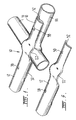
- connection 10 is made between three tubular frame members 12,14,16.
- the members are each 25.4 mm diameter steel pipe, although other sizes (such as 31.7 mm diameter steel pipe) or other metals (such as aluminium) or materials may be used.
- the members 12,14,16 have a circular cross-section, but it will become clear that the invention is also capable of application to members having a non-circular cross-section.
- Members 12,14,16 may be straight or curved.
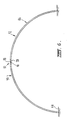
- members 12,14 are curved supporting frame members 48 for a greenhouse, and member 16 is a straight cross-member (see Fig. 6).
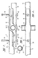
- the ends 18,20 of members 12,14 are deformed, in that lengths of each member at the ends 18,20 are pressed or otherwise deformed into the crescent (in cross-section) profiles 32,34 which are illustrated in Figs. 3 and 5.
- a second deformation is made in each end 18,20 to provide curved profiles 22, 24 at, in this embodiment, right angles to the axis of each member.
- the second deformations could be made at other angles to the axes of the members 12,14.
- the deformation steps may also include a minor deformation 26 of each end on the inner side of deformations 22, 24 to provide a smoother external appearance for the connection 10. Deformation 26 is best illustrated in Fig. 3.
- a pair of apertures 28,30 is provided in each end 18,20 or may be drilled in situ.
- apertures 28,30 of members 12,14 are in register.
- Bolts 36,38 are adapted to be passed through registering apertures 36,38.
- Cross-member 16 is located between members 12,14 within profiles 22,24 before the bolting action takes place,with nuts 40,42 being tightened on bolts 36,38 to draw ends 18,20 together, thereby securely clamping member 16 therebetween.
- the 'hoop' 46 of Fig. 6 is preferably dimensioned so that it is 1.98 m from the ground at its highest point, and is 4.26 from base to base.
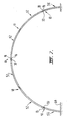
- Fig. 6 shows a larger greenhouse 'hoop' 50, having dimensions of a maximum height of 3.2 m and a width of 6.71 m.
- hoop elements 52,54 made from 31.7 mm steel tube, are used. Elements 52 are 'full', in that they have ends 18 and 20. These make three connections 10, and two further connections are made with 'half' elements 54, which only have one deformed end 18 or 20.
- connection 10 of this embodiment is extremely strong, and provides a firm, rigid connection between the members 12,14 and 16. Its flattened external shape is suitable for the location of polythene sheet thereon, in a greenhouse application.
- connection 10 may be used for other structures, such as other type buildings, scaffolding or fencing, or for any other application where members are to be joined.
- the deformation of the members need not take place at the very ends thereof, although it seems likely that the deformation may have to occur near the ends.
Landscapes
- Engineering & Computer Science (AREA)
- General Engineering & Computer Science (AREA)
- Mechanical Engineering (AREA)
- Life Sciences & Earth Sciences (AREA)
- Environmental Sciences (AREA)
- Mutual Connection Of Rods And Tubes (AREA)
- Joining Of Building Structures In Genera (AREA)
Applications Claiming Priority (1)
| Application Number | Priority Date | Filing Date | Title |
|---|---|---|---|
| AU360884 | 1984-02-14 |
Publications (1)
| Publication Number | Publication Date |
|---|---|
| EP0213250A1 true EP0213250A1 (fr) | 1987-03-11 |
Family
ID=3694058
Family Applications (1)
| Application Number | Title | Priority Date | Filing Date |
|---|---|---|---|
| EP85630128A Withdrawn EP0213250A1 (fr) | 1984-02-14 | 1985-08-13 | Procédé pour fixer des pièces et fixation suivant ce procédé |
Country Status (2)
| Country | Link |
|---|---|
| EP (1) | EP0213250A1 (fr) |
| AU (1) | AU3873985A (fr) |
Cited By (4)
| Publication number | Priority date | Publication date | Assignee | Title |
|---|---|---|---|---|
| EP0739793A1 (fr) * | 1995-04-28 | 1996-10-30 | Valeo Systemes D'essuyage | Mécanisme d'essuie glace pour véhicule automobile comportant un élément de structure démontable |
| FR2788290A1 (fr) * | 1999-01-13 | 2000-07-13 | Sarl Barre | Structure de batiment du type serre a usage agricole ou autre |
| US7377714B2 (en) * | 2003-04-03 | 2008-05-27 | Reeves Francis J | Mechanical joint for collapsible structures |
| US8657521B2 (en) | 2011-01-13 | 2014-02-25 | First Goal Llc | Collapsible structures and joints for collapsible structures |
Families Citing this family (1)
| Publication number | Priority date | Publication date | Assignee | Title |
|---|---|---|---|---|
| AU596917B2 (en) * | 1987-11-02 | 1990-05-17 | Tubemakers Of Australia Limited | An adjustable coupling |
Citations (3)
| Publication number | Priority date | Publication date | Assignee | Title |
|---|---|---|---|---|
| US2408907A (en) * | 1944-08-31 | 1946-10-08 | Noblitt Sparks Ind Inc | Metal furniture |
| US2881017A (en) * | 1956-10-11 | 1959-04-07 | Jr John Millar | Coupling for tubing |
| NL6404511A (fr) * | 1964-04-23 | 1965-10-25 |
-
1984
- 1984-02-14 AU AU38739/85A patent/AU3873985A/en not_active Abandoned
-
1985
- 1985-08-13 EP EP85630128A patent/EP0213250A1/fr not_active Withdrawn
Patent Citations (3)
| Publication number | Priority date | Publication date | Assignee | Title |
|---|---|---|---|---|
| US2408907A (en) * | 1944-08-31 | 1946-10-08 | Noblitt Sparks Ind Inc | Metal furniture |
| US2881017A (en) * | 1956-10-11 | 1959-04-07 | Jr John Millar | Coupling for tubing |
| NL6404511A (fr) * | 1964-04-23 | 1965-10-25 |
Non-Patent Citations (1)
| Title |
|---|
| DERWENT ABSTRACT, nr. 85-249396, Week 8541; & AU - A - 85 38 739 (COLE) * |
Cited By (5)
| Publication number | Priority date | Publication date | Assignee | Title |
|---|---|---|---|---|
| EP0739793A1 (fr) * | 1995-04-28 | 1996-10-30 | Valeo Systemes D'essuyage | Mécanisme d'essuie glace pour véhicule automobile comportant un élément de structure démontable |
| FR2733475A1 (fr) * | 1995-04-28 | 1996-10-31 | Valeo Systemes Dessuyage | Mecanisme d'essuie-glace pour vehicule automobile comportant un element de structure demontable |
| FR2788290A1 (fr) * | 1999-01-13 | 2000-07-13 | Sarl Barre | Structure de batiment du type serre a usage agricole ou autre |
| US7377714B2 (en) * | 2003-04-03 | 2008-05-27 | Reeves Francis J | Mechanical joint for collapsible structures |
| US8657521B2 (en) | 2011-01-13 | 2014-02-25 | First Goal Llc | Collapsible structures and joints for collapsible structures |
Also Published As
| Publication number | Publication date |
|---|---|
| AU3873985A (en) | 1985-08-22 |
Similar Documents
| Publication | Publication Date | Title |
|---|---|---|
| US4577449A (en) | Prefabricated structural connector for steel-frame buildings | |
| US6340141B1 (en) | Cable support systems, methods, and rack therefor | |
| US6896437B2 (en) | Fence panel and connector therefor | |
| GB1601912A (en) | Roll over protective structure | |
| EP0070281B1 (fr) | Tube de support pour une construction tubulaire et son procede de fabrication | |
| US4430839A (en) | Scaffold frame | |
| EP0807501B1 (fr) | Coffrage de forme allongée à courbure variable | |
| JP3877797B2 (ja) | 曲率可変の湾曲骨組体の組立構造 | |
| GB2348617A (en) | Railings | |
| JP3848406B2 (ja) | 曲率可変の湾曲骨組体 | |
| GB2210129A (en) | Improvements in scaffold and like frames | |
| JPH02274962A (ja) | 階段用仮設手摺り装置 | |
| GB2357782A (en) | Fence panel construction | |
| US2876048A (en) | Scaffold assembly | |
| JPH11229621A (ja) | 連結金具を備えた作業足場用支柱 | |
| JPH09228486A (ja) | アルミニウム合金製部材の連結構造及び連結部材の成形方法 | |
| JP3804692B2 (ja) | 曲率可変の湾曲骨組体 | |
| JPH071477Y2 (ja) | 支柱と線格子フエンス体との連結構造 | |
| JPH0624009U (ja) | 落石防止柵のコーナー部構造 | |
| JPS6241843A (ja) | 部材の連結方法 | |
| JPH0312124Y2 (fr) | ||
| WO1992019870A1 (fr) | Element d'echafaudage et plate-forme de travail | |
| JPH10266579A (ja) | 仮覆いの肋骨連結装置 | |
| AU662561B2 (en) | Building element | |
| AU781766B2 (en) | Safety rail support assembly |
Legal Events
| Date | Code | Title | Description |
|---|---|---|---|
| PUAI | Public reference made under article 153(3) epc to a published international application that has entered the european phase |
Free format text: ORIGINAL CODE: 0009012 |
|
| AK | Designated contracting states |
Kind code of ref document: A1 Designated state(s): AT BE CH DE FR GB IT LI LU NL SE |
|
| STAA | Information on the status of an ep patent application or granted ep patent |
Free format text: STATUS: THE APPLICATION IS DEEMED TO BE WITHDRAWN |
|
| 18D | Application deemed to be withdrawn |
Effective date: 19870911 |