EP0213690A2 - Ventilierter Glasflaschenbehälter zur Minderung statischer Elektrizität - Google Patents
Ventilierter Glasflaschenbehälter zur Minderung statischer Elektrizität Download PDFInfo
- Publication number
- EP0213690A2 EP0213690A2 EP86303854A EP86303854A EP0213690A2 EP 0213690 A2 EP0213690 A2 EP 0213690A2 EP 86303854 A EP86303854 A EP 86303854A EP 86303854 A EP86303854 A EP 86303854A EP 0213690 A2 EP0213690 A2 EP 0213690A2
- Authority
- EP
- European Patent Office
- Prior art keywords
- vial
- holder
- sized
- small
- sample
- Prior art date
- Legal status (The legal status is an assumption and is not a legal conclusion. Google has not performed a legal analysis and makes no representation as to the accuracy of the status listed.)
- Withdrawn
Links
- 230000003068 static effect Effects 0.000 title claims abstract description 43
- 230000005611 electricity Effects 0.000 title claims abstract description 16
- 150000002500 ions Chemical class 0.000 claims abstract description 34
- 238000003345 scintillation counting Methods 0.000 claims abstract description 3
- 230000003287 optical effect Effects 0.000 claims description 2
- 229940000425 combination drug Drugs 0.000 claims 1
- 230000008030 elimination Effects 0.000 abstract 1
- 238000003379 elimination reaction Methods 0.000 abstract 1
- 230000032258 transport Effects 0.000 abstract 1
- 239000007788 liquid Substances 0.000 description 12
- 239000011521 glass Substances 0.000 description 4
- 238000005567 liquid scintillation counting Methods 0.000 description 3
- 238000005259 measurement Methods 0.000 description 3
- 230000003472 neutralizing effect Effects 0.000 description 3
- 238000013461 design Methods 0.000 description 2
- 239000000463 material Substances 0.000 description 2
- 230000001737 promoting effect Effects 0.000 description 2
- 238000004458 analytical method Methods 0.000 description 1
- 150000001875 compounds Chemical class 0.000 description 1
- 238000010276 construction Methods 0.000 description 1
- 238000001514 detection method Methods 0.000 description 1
- 230000000694 effects Effects 0.000 description 1
- 239000002803 fossil fuel Substances 0.000 description 1
- 230000005865 ionizing radiation Effects 0.000 description 1
- 238000000034 method Methods 0.000 description 1
- 238000012986 modification Methods 0.000 description 1
- 230000004048 modification Effects 0.000 description 1
- 238000012544 monitoring process Methods 0.000 description 1
- 230000007935 neutral effect Effects 0.000 description 1
- 238000011002 quantification Methods 0.000 description 1
Images

Classifications
-
- G—PHYSICS
- G01—MEASURING; TESTING
- G01T—MEASUREMENT OF NUCLEAR OR X-RADIATION
- G01T1/00—Measuring X-radiation, gamma radiation, corpuscular radiation, or cosmic radiation
- G01T1/16—Measuring radiation intensity
- G01T1/20—Measuring radiation intensity with scintillation detectors
- G01T1/204—Measuring radiation intensity with scintillation detectors the detector being a liquid
-
- G—PHYSICS
- G01—MEASURING; TESTING
- G01T—MEASUREMENT OF NUCLEAR OR X-RADIATION
- G01T1/00—Measuring X-radiation, gamma radiation, corpuscular radiation, or cosmic radiation
- G01T1/16—Measuring radiation intensity
- G01T1/20—Measuring radiation intensity with scintillation detectors
- G01T1/204—Measuring radiation intensity with scintillation detectors the detector being a liquid
- G01T1/2042—Composition for liquid scintillation systems
- G01T1/2047—Sample preparation
-
- G—PHYSICS
- G01—MEASURING; TESTING
- G01T—MEASUREMENT OF NUCLEAR OR X-RADIATION
- G01T7/00—Details of radiation-measuring instruments
- G01T7/02—Collecting means for receiving or storing samples to be investigated and possibly directly transporting the samples to the measuring arrangement; particularly for investigating radioactive fluids
Definitions
- This invention relates to a holder adapted for use with a scintillation counter, which acts to secure small-sized glass and plastic vials within a vial transport carrier and includes means for promoting the elemination of static electricity charges on the surface of the vial containing the sample to be tested.
- Electrostatic discharge is a photon producing interference in liquid scintillation counting.
- Liquid scintillation counting is an analytical method for quantification of radioactivity by measuring emitted light from a sample. The photons produced in a detection chamber by causes other than nuclear decay will interfere with the measurement. Photon producing interference such as static discharge is sufficiently close to the pulse generated by light produced from nuclear decay events that it may be interpreted as a nuclear event thereby affecting the reliability of the output of the liquid scintillation counter.
- Static electricity consists of charged ions, positive or negative, which are atoms that are electrically out of balance due to the removal or addition of one or more electrons. Like magnets, ions of like charge repel and of dislike charge attract.
- Static charges can develop on a scintillation vial or in a scintillation cocktail. Static charges on the vial surface can be produced during shipping and as a result of movement in the sample changer of a liquid scintillation counter. Glass vials have less problems with static charge buildup than do plastic vials. Small vials in adapters or holders are particularly prone to static charge buildup.
- counter-charged ions In order to control the buildup of static electricity, one of the methods used has been to present an atmosphere of counter-charged ions to the surface charged with static electricity.
- the counter ions annihilate the surface static charge resulting in a neutral surface effect.
- These counter ions may be produced either by ionizing radiation or electricity.
- Utilizing electrical current to generate an ionized atmosphere of mixed counter ions has been commercially successful.
- An annular-shaped electrostatic device has been utilized commercially and is located within a liquid scintillation counter such that as a sample vial is removed from the vial transport carrier and transported to the measurement chamber, the vial interacts with charged ions produced by the electrostatic device. In a short time, such as two seconds, the ions generated by the electrostatic device act to neutralize the static electricity on the vial.
- the electrostatic device works by supplying a high voltage to the surrounding atmosphere which causes a localized electrical disturbance around each electrode resulting in the production of counter ions. As the vial containing the sample is passed through the control device, the counter ions passively migrate to the vial surface and act to neutralize accumulated charged ions.
- the herein invention is directed toward providing openings in the adapter to promote this flow of charged ions such that a small vial contained within an adapter is appropriately treated to minimize the static charges on the surface of the vial.
- Scintillation vials are typically manufactured from glass or fossil fuel derived compounds. Small vials are extremely sensitive to the buildup of static electricity and even more so if made of plastic. Hence, it is extremely important that means be provided for minimizing static electricty from the surface of a small plastic or glass vial.
- a holder for securing a small vial in a vial transport carrier sized to receive large vials, both small and large vials containing a sample to be placed in a scintillation counter.
- the holder includes a body means of similar size and configuration to a large vial and including a central opening for maintaining a small vial within the body means, and said body means further defining openings sized to allow an atmosphere of charged ions to flow through the openings to the small vial for the purpose of eliminating static charges on the surface of the small vial secured within the holder.
- a vial transport carrier designed for large vials and for maintaining the ability of a liquid scintillation counter to minimize static charges on the surface of a small vial as the small vial is passed through a static eliminator prior to being tested.
- the holder is sized to fit within the vial transport carrier and includes means for securing a small vial within the holder.
- the holder further defines openings which allow the passage of air containing charged ions, said ions being created by the static eliminator and said ions flowing through the openings of the holder to neutralize any static charge in the surface of the small vial.
- a holder 10 having body 30 and top portion 20.
- the top portion 20 is generally annular in configuration and includes a holding annulus 22 at the top thereof and a snap annulus 24 at the bottom thereof.
- Interior wall 28 extends between the holding annulus and the snap annulus defining a central opening 26 into which the small vial may be secured.
- Top surface 29 of holding annulus 22 is designed to allow a cap or other portion of a small vial to rest thereon as it is centered within the holder by opening 26.
- Body portion 30 of holder 10 defines openings 32, 34 and 36 spaced about the circumference of the body. It is through these openings that the charged ions may flow to reach the vial located therewithin. Central opening 39 extends axially the length of the body 30 and it is within this central opening that the small vial is secured.
- Body 30 additionally includes a top surface 38 on which the holding annulus 22 of the top portion may rest.
- Snap slot 40 is defined on the interior of the body and is sized to mate with snap annulus 24 of the top portion such that the top portion is secured to the body by force-fit with the snap annulus secured within the snap slot. Additional openings 42, 44, and 46 are located about the lower portion of the body for promoting additional ion flow therethrough.
- Support base 48 is an annular support to which the bottom of the sample vial may be secured. Being annular in configuration, the support base 48 not only acts to maintain the vial at the appropriate height within the holder but also acts to center it as well.
- Figure 2 is a sectional view of Figure 1 taken at line II-II. In this view openings 32 and 34 and the body portions 30 may be specifically seen. It also may be seen that snap annulus 24 is secured within snap slot 40 and that holding annulus 22 rests on the top of body 30.
- small vial 50 having cap 56 attached thereto and defining side walls 52 and bottom wall 54 may be secured within the holder.
- the small vial is secured in the central opening of the body and the bottom wall 54 of the small vial rests within support base 48 which both supports the vial in the vertical direction and acts to center the vial.
- Cap 56 may or may not rest upon holding annulus 22 depending upon the design of the small vial.
- the side walls 52 of the small vial engage interior wall 28 of the top portion to maintain the top portion of the vial in the desired position.
- the vial top portion may be in contact with wall 28 and the bottom portion may be in contact with support base 48 such that vial 50 is secured in the desired position within holder 10.
- openings 32, 34, as well as openings 42, and 44 allow charged ions to enter the interior central opening of the holder to interact with the vial surface. Naturally, these charged ions also interact with the holder and eliminate any static electricity that may accumulate there.
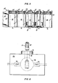
- Figure 5 is a cutaway view of a vial transport carrier showing positions A through E.
- the number of positions in a vial transport carrier may vary depending upon numerous factors related to the specific counter and vial transport carrier design.
- FIG 5 at positions A, B and E, are shown large vials 80 having caps 82.
- This vial transport carrier 60 is designed to have each position sized to specifically hold a large vial as shown.
- positions C and D are shown holders 10 into which small vials 50 have been placed. It may be seen that holder 10 is approximately the same exterior size and configuration as large vial 80 such that it is maintained within the appropriate position of vial transport carrier 60 as defined by divider 62 and back wall 64.
- large vial 80 may be removed from a position of the vial transport carrier or a holder containing a small vial 50 may be removed from a position of the vial transport carrier without any change in the mechanical operation of the liquid scintillation counter.
- FIG. 6 is a schematic view of a liquid scintillation counter.
- Cavity 98 otherwise known as the sample chamber is shown located within shielding 84 and has a pair of photomultiplier tubes PMT (94) located on either side of the cavity for monitoring optical events.
- the vial and holder would typically be secured within vial transport carrier 60 although not shown in this Figure.
- vial 50 and holder 70 are sized to be displaced downwardly, through static eliminator 90 and through passageway 92.
- Static eliminator 90 is the high voltage device which charges ions and allows these ions to be placed in the airstream for neutralizing the ions on the holder or vial. The sample then continues downwardly to cavity 98.
- the structure herein has been described to show that the holder for containing a small-sized vial located in a vial transport carrier having larger-sized positions is extremely important for obtaining accurate counting results.
- a holder having openings which allow charged ions to eliminate static electricity on the vial the overall accuracy of the liquid scintillation counting results is improved.
Landscapes
- Physics & Mathematics (AREA)
- Health & Medical Sciences (AREA)
- Life Sciences & Earth Sciences (AREA)
- General Physics & Mathematics (AREA)
- High Energy & Nuclear Physics (AREA)
- Molecular Biology (AREA)
- Spectroscopy & Molecular Physics (AREA)
- Chemical & Material Sciences (AREA)
- Analytical Chemistry (AREA)
- Sampling And Sample Adjustment (AREA)
- Measurement Of Radiation (AREA)
Applications Claiming Priority (2)
| Application Number | Priority Date | Filing Date | Title |
|---|---|---|---|
| US77131885A | 1985-08-30 | 1985-08-30 | |
| US771318 | 1996-12-20 |
Publications (1)
| Publication Number | Publication Date |
|---|---|
| EP0213690A2 true EP0213690A2 (de) | 1987-03-11 |
Family
ID=25091428
Family Applications (1)
| Application Number | Title | Priority Date | Filing Date |
|---|---|---|---|
| EP86303854A Withdrawn EP0213690A2 (de) | 1985-08-30 | 1986-05-21 | Ventilierter Glasflaschenbehälter zur Minderung statischer Elektrizität |
Country Status (4)
| Country | Link |
|---|---|
| EP (1) | EP0213690A2 (de) |
| JP (1) | JPS6255586A (de) |
| AU (1) | AU6119686A (de) |
| FI (1) | FI862472L (de) |
Cited By (3)
| Publication number | Priority date | Publication date | Assignee | Title |
|---|---|---|---|---|
| WO2004026735A3 (en) * | 2002-09-17 | 2005-08-04 | Glaxosmithkline Biolog Sa | Article holding means and conveyor system |
| US8567267B2 (en) | 2011-01-21 | 2013-10-29 | Wallac Oy | Method and device for cutting off one or more sample regions from a sample carrier |
| JP2015158420A (ja) * | 2014-02-24 | 2015-09-03 | 日立アロカメディカル株式会社 | 水モニタ校正用線源ユニット |
-
1986
- 1986-05-21 EP EP86303854A patent/EP0213690A2/de not_active Withdrawn
- 1986-06-10 FI FI862472A patent/FI862472L/fi not_active Application Discontinuation
- 1986-08-14 JP JP61191176A patent/JPS6255586A/ja active Pending
- 1986-08-15 AU AU61196/86A patent/AU6119686A/en not_active Abandoned
Cited By (4)
| Publication number | Priority date | Publication date | Assignee | Title |
|---|---|---|---|---|
| WO2004026735A3 (en) * | 2002-09-17 | 2005-08-04 | Glaxosmithkline Biolog Sa | Article holding means and conveyor system |
| EP1854748A3 (de) * | 2002-09-17 | 2010-07-28 | Aseptic Technologies S.A. | Neuartige Vorrichtung |
| US8567267B2 (en) | 2011-01-21 | 2013-10-29 | Wallac Oy | Method and device for cutting off one or more sample regions from a sample carrier |
| JP2015158420A (ja) * | 2014-02-24 | 2015-09-03 | 日立アロカメディカル株式会社 | 水モニタ校正用線源ユニット |
Also Published As
| Publication number | Publication date |
|---|---|
| FI862472A7 (fi) | 1987-03-01 |
| JPS6255586A (ja) | 1987-03-11 |
| FI862472A0 (fi) | 1986-06-10 |
| FI862472L (fi) | 1987-03-01 |
| AU6119686A (en) | 1987-03-05 |
Similar Documents
| Publication | Publication Date | Title |
|---|---|---|
| US5055674A (en) | Electret ionization chamber for monitoring radium and dissolved radon in water | |
| US5117190A (en) | Electrostatic detector of aerosol particles | |
| US5550381A (en) | Event counting alpha detector | |
| JPH11514742A (ja) | 超低バックグラウンド多光子検出器 | |
| US5241569A (en) | Imaging radionuclide analysis apparatus and method | |
| EP0213690A2 (de) | Ventilierter Glasflaschenbehälter zur Minderung statischer Elektrizität | |
| McKlveen et al. | Simultaneous alpha and beta particle assay using liquid scintillation counting with pulse-shape discrimination | |
| EP0601050B1 (de) | Gasdurchfluss-zählrohr vom geiger-müller typ und verfahren zur überwachung ionisierender strahlungen | |
| US4924093A (en) | Beta counting means and apparatus | |
| McDaniel et al. | Impurity determination in electronic materials by accelerator mass spectrometry | |
| GB2301222A (en) | Surface radioactivity monitor | |
| US2917634A (en) | Nuclear radiation counters | |
| US20060051494A1 (en) | Method, device and system for the temporary marking of objects | |
| US4695728A (en) | Portable radiation contamination detector | |
| RU2113718C1 (ru) | Способ измерения радиоактивности газов по альфа-излучению, в частности радиоактивности воздуха, содержащего радон и торон | |
| US5338938A (en) | Gamma radiation field intensity meter | |
| RU2010265C1 (ru) | Способ определения концентрации радона и его дочерних продуктов в воздухе и устройство для его осуществления | |
| Buchtela | Gas ionization detectors | |
| US5942757A (en) | Monitor for measuring the radioactivity of a surface | |
| JP2006145391A (ja) | 放射線測定装置及び放射性廃棄物検査方法 | |
| US6452190B1 (en) | Radiation detector provided with an absorption chamber and a plurality of avalanche chambers | |
| Strauss et al. | X/gamma-ray measurements of total activity in environmental samples without prior knowledge of isotopic abundance | |
| EP0533665B1 (de) | Verfahren zur bestimmung der probenaktivität in einem mit mehreren detektoren versehenen flüssigkeitsszintillationszähler | |
| WO1993003911A1 (en) | Static free coated sample vials for scintillation spectrometry | |
| Parus et al. | Analysis of uranium and plutonium materials by radiometric methods |
Legal Events
| Date | Code | Title | Description |
|---|---|---|---|
| PUAI | Public reference made under article 153(3) epc to a published international application that has entered the european phase |
Free format text: ORIGINAL CODE: 0009012 |
|
| AK | Designated contracting states |
Kind code of ref document: A2 Designated state(s): DE FR GB SE |
|
| STAA | Information on the status of an ep patent application or granted ep patent |
Free format text: STATUS: THE APPLICATION IS DEEMED TO BE WITHDRAWN |
|
| 18D | Application deemed to be withdrawn |
Effective date: 19880601 |
|
| RIN1 | Information on inventor provided before grant (corrected) |
Inventor name: DE FILIPPIS, JOHN STANLEY Inventor name: O'DAY, BENEDICT RAYMOND |