EP0214005A1 - Kunststoffspule für Magnetband innerhalb einer Kassette - Google Patents
Kunststoffspule für Magnetband innerhalb einer Kassette Download PDFInfo
- Publication number
- EP0214005A1 EP0214005A1 EP86401663A EP86401663A EP0214005A1 EP 0214005 A1 EP0214005 A1 EP 0214005A1 EP 86401663 A EP86401663 A EP 86401663A EP 86401663 A EP86401663 A EP 86401663A EP 0214005 A1 EP0214005 A1 EP 0214005A1
- Authority
- EP
- European Patent Office
- Prior art keywords
- flange
- hub
- central hole
- brake
- coil according
- Prior art date
- Legal status (The legal status is an assumption and is not a legal conclusion. Google has not performed a legal analysis and makes no representation as to the accuracy of the status listed.)
- Granted
Links
- 239000004033 plastic Substances 0.000 title claims abstract description 8
- 229920003023 plastic Polymers 0.000 title claims abstract description 8
- 230000003014 reinforcing effect Effects 0.000 claims abstract description 5
- 238000004804 winding Methods 0.000 claims abstract description 5
- 230000002787 reinforcement Effects 0.000 claims description 9
- 238000003466 welding Methods 0.000 claims description 5
- 238000006386 neutralization reaction Methods 0.000 claims description 2
- 238000004026 adhesive bonding Methods 0.000 claims 1
- 239000002184 metal Substances 0.000 abstract description 4
- 239000000463 material Substances 0.000 abstract description 3
- 230000008602 contraction Effects 0.000 description 2
- 239000003365 glass fiber Substances 0.000 description 2
- 239000004417 polycarbonate Substances 0.000 description 2
- 229920000515 polycarbonate Polymers 0.000 description 2
- 229930182556 Polyacetal Natural products 0.000 description 1
- 239000000470 constituent Substances 0.000 description 1
- 230000000694 effects Effects 0.000 description 1
- 238000004519 manufacturing process Methods 0.000 description 1
- 238000000465 moulding Methods 0.000 description 1
- 230000003472 neutralizing effect Effects 0.000 description 1
- 230000000149 penetrating effect Effects 0.000 description 1
- 230000002093 peripheral effect Effects 0.000 description 1
- 229920006324 polyoxymethylene Polymers 0.000 description 1
- 239000002990 reinforced plastic Substances 0.000 description 1
- 238000000926 separation method Methods 0.000 description 1
Images


Classifications
-
- G—PHYSICS
- G11—INFORMATION STORAGE
- G11B—INFORMATION STORAGE BASED ON RELATIVE MOVEMENT BETWEEN RECORD CARRIER AND TRANSDUCER
- G11B23/00—Record carriers not specific to the method of recording or reproducing; Accessories, e.g. containers, specially adapted for co-operation with the recording or reproducing apparatus ; Intermediate mediums; Apparatus or processes specially adapted for their manufacture
- G11B23/02—Containers; Storing means both adapted to cooperate with the recording or reproducing means
- G11B23/037—Single reels or spools
Definitions
- the present invention relates to improvements made to a plastic reel for magnetic tape, isolated from a cassette case.
- such a known coil comprises a hollow cylindrical hub 1 of large diameter provided for the winding of a magnetic strip 2.
- This hub came from molding with a flange 3, the whole being constituted by a reinforced plastic, preferably by a polycarbonate reinforced with glass fibers.
- the flange 3 extends from its peripheral edge 4 defining the filling capacity up to a central hole 5 intended for the passage of a pusher 6 capable of penetrating into the internal cavity 7 of the hub.
- This flange 3 has, on the outside, a toothed crown 8 for driving in rotation and, inside, a toothed immobilization track 9 located substantially opposite the crown.
- the flange 3 is further provided with a washer or metal insert 10 overmolded.
- the coil is centered by an annular groove 11 of its flange 3 on a collar of the case which contains it; it is therefore mounted unacceptable relative to the latter and are then visible outside said toothed ring 8 for its rotation drive and said metal insert for its cooperation with the drive head which comprises the pusher 6 above.
- the free edge 12 of the hub 1 is centered in a flange 13 of a second flange 14 of unreinforced plastic, such as polycarbonate, and this edge 12 is fixed at the end to this second flange by ultrasonic welding at 15 (FIG. 2 ).
- a brake 16 may be introduced into the cavity 7 through a passage 17 delimited by the rim 13 of the second flange. This brake is pushed back by a spring bearing on the housing to cooperate with the toothed immobilization track 9 and it can be neutralized by axial separation under the action of the pusher 6.
- the storage or use of the signals recorded on the magnetic tape 2 requires: - a geometrically perfect winding hub 1 and the highest possible compressive strength, - geometrically stable flanges 3.14 so as not to deteriorate, by their deformation, the magnetic strip 2 in particular by friction.
- the hub 1 deforms into a cone and the same applies to the strip wafer 2.
- the attached flange 14 deforms, in particular due to the radial contraction of the relatively narrow welded ring 15, and comes to touch the strip.
- Figure 4 shows the effect obtained by the friction of the edge of said strip 2 against the flange 14: this strip wears on one side, friezes and undulates. Therefore, its use becomes impossible.
- the object of the present invention is to remedy these drawbacks by perfecting this plastic reel so that it no longer deforms under severe conditions of use and thus the magnetic tape no longer wears out and can be used normally.
- the second flange has a coronal extension extending towards the center and trapping the brake in the cavity of the hub thus partially closed, a brake whose axial neutralization stroke is limited.
- the coronal extension of the second flange is reinforced by a washer, preferably metallic, fixed to the latter.
- the coil may include internal reinforcement both of the hub and of the fixing thereof on the second flange.
- the reinforcement is a tubular sleeve concentric with the hub and also molded with the first flange, this sleeve and this first flange being preferably connected by axial ribs.
- the reinforcement consists of a plurality of internal ribs projecting inside the hub.
- the reinforcing elements are fixed at the end to the second flange to increase the radial extent of the fixing zone, this fixing being able to be carried out by ultrasonic welding, by bonding, by riveting or other.
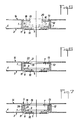
- the annular rim 13 of the attached flange 14 is molded with a coronal extension 18 which partially closes the wide passage 17.
- This extension 18 extends towards the center and delimits a central hole 19.
- the brake is therefore trapped of the cavity 7 and must be mounted before the flange 14 is fitted and fixed to the hub 1. Only the end piece 20 of the brake and the spring of the housing which surrounds it pass through the hole 19. Thus, the coil is found does it stiffen by this hub.
- the coronal extension 18 can be reinforced, as shown in FIG. 6, by a washer 21 preferably metallic, which is fixed there by any suitable means, such as riveting 22, welding, bonding, overmolding or other.
- this washer 21 can be made, as is also the reinforcing washer 10, by another material with high mechanical strength, such as a reinforced or unarmoured plastic and more especially a polyacetal; in this case, the washer 10 can be, like the washer 21, fixed by other means than overmolding.
- the reinforcement consists of a tubular sleeve 23 extending concentrically with the hub 1.
- the sleeve 23 and the hub 1 are molded with the flange 3 and are both fixed at the end on the second flange 14 and its extension 18 in order to separate the annular fixing zones and thus to stiffen the connection with said flange 14.
- edges 12 of the hub 1 and 24 of the sleeve 23 are fixed by ultrasonic welding respectively at 15 and 25 on the flange 14 and the extension 18.
- the edge of the sleeve 23 has protruding studs 26 passing through holes 27 of the extension 18 and riveted on the other side to form retaining heads 28.
- the hub 1 and the sleeve 23 are joined together by axial ribs 29 molded with them to further improve stiffening. These ribs may or may not be fixed to the opposite flange 14.
- the internal reinforcement of the hub 1 can be free of sleeve 23 and limited to ribs 30 projecting freely inside said hub 1.
- the ribs are axial, but they can be shaped differently, particularly in the form of a helix, if demoulding allows.
Landscapes
- Storage Of Web-Like Or Filamentary Materials (AREA)
- Braking Arrangements (AREA)
Applications Claiming Priority (2)
| Application Number | Priority Date | Filing Date | Title |
|---|---|---|---|
| FR8512422A FR2586319B1 (fr) | 1985-08-14 | 1985-08-14 | Bobine en matiere plastique pour bande magnetique, prisonniere d'un boitier de cassette |
| FR8512422 | 1985-08-14 |
Publications (2)
| Publication Number | Publication Date |
|---|---|
| EP0214005A1 true EP0214005A1 (de) | 1987-03-11 |
| EP0214005B1 EP0214005B1 (de) | 1990-05-23 |
Family
ID=9322251
Family Applications (1)
| Application Number | Title | Priority Date | Filing Date |
|---|---|---|---|
| EP19860401663 Expired - Lifetime EP0214005B1 (de) | 1985-08-14 | 1986-07-24 | Kunststoffspule für Magnetband innerhalb einer Kassette |
Country Status (3)
| Country | Link |
|---|---|
| EP (1) | EP0214005B1 (de) |
| DE (1) | DE3671561D1 (de) |
| FR (1) | FR2586319B1 (de) |
Cited By (2)
| Publication number | Priority date | Publication date | Assignee | Title |
|---|---|---|---|---|
| WO1994029864A1 (en) * | 1993-06-08 | 1994-12-22 | Minnesota Mining And Manufacturing Company | Single reel cartridge reel with improved weld design |
| EP0702829B1 (de) * | 1993-06-08 | 1998-02-04 | Minnesota Mining And Manufacturing Company | Einspulige kassette mit verbesserter zusammensetzung |
Citations (5)
| Publication number | Priority date | Publication date | Assignee | Title |
|---|---|---|---|---|
| GB2010218A (en) * | 1977-12-16 | 1979-06-27 | Sony Corp | Tape reels |
| GB2018224A (en) * | 1978-03-07 | 1979-10-17 | Dai Ichi Seiko Co Ltd | Tape reel |
| GB2028272A (en) * | 1978-08-11 | 1980-03-05 | Nifco Inc | Tape reel for video tape cassette |
| FR2445583A1 (fr) * | 1978-12-25 | 1980-07-25 | Nifco Inc | Bobine pour bande video en cassette |
| DE3108585A1 (de) * | 1980-03-07 | 1982-02-04 | Nifco Inc., Yokohama, Kanagawa | Bandspule |
-
1985
- 1985-08-14 FR FR8512422A patent/FR2586319B1/fr not_active Expired
-
1986
- 1986-07-24 EP EP19860401663 patent/EP0214005B1/de not_active Expired - Lifetime
- 1986-07-24 DE DE8686401663T patent/DE3671561D1/de not_active Expired - Fee Related
Patent Citations (5)
| Publication number | Priority date | Publication date | Assignee | Title |
|---|---|---|---|---|
| GB2010218A (en) * | 1977-12-16 | 1979-06-27 | Sony Corp | Tape reels |
| GB2018224A (en) * | 1978-03-07 | 1979-10-17 | Dai Ichi Seiko Co Ltd | Tape reel |
| GB2028272A (en) * | 1978-08-11 | 1980-03-05 | Nifco Inc | Tape reel for video tape cassette |
| FR2445583A1 (fr) * | 1978-12-25 | 1980-07-25 | Nifco Inc | Bobine pour bande video en cassette |
| DE3108585A1 (de) * | 1980-03-07 | 1982-02-04 | Nifco Inc., Yokohama, Kanagawa | Bandspule |
Cited By (3)
| Publication number | Priority date | Publication date | Assignee | Title |
|---|---|---|---|---|
| WO1994029864A1 (en) * | 1993-06-08 | 1994-12-22 | Minnesota Mining And Manufacturing Company | Single reel cartridge reel with improved weld design |
| EP0702829B1 (de) * | 1993-06-08 | 1998-02-04 | Minnesota Mining And Manufacturing Company | Einspulige kassette mit verbesserter zusammensetzung |
| US5868338A (en) * | 1993-06-08 | 1999-02-09 | Imation Corp. | Single reel cartridge with improved housing assembly |
Also Published As
| Publication number | Publication date |
|---|---|
| FR2586319A1 (fr) | 1987-02-20 |
| DE3671561D1 (de) | 1990-06-28 |
| EP0214005B1 (de) | 1990-05-23 |
| FR2586319B1 (fr) | 1987-12-18 |
Similar Documents
| Publication | Publication Date | Title |
|---|---|---|
| CH663679A5 (fr) | Bobine en matiere plastique pour bande magnetique, prisonniere d'un boitier de cassette. | |
| EP2308532B1 (de) | Sicherheitsvorrichtung für eine Spritze und Anordnung bestehend aus dieser Vorrichtung und einer Spritze | |
| CA1147296A (fr) | Contenant pour produits rigides tels que batonnets, mines de stylo et analogues | |
| EP0196931B1 (de) | Kabelzug mit selbsttätiger Nachstellvorrichtung | |
| EP1551219A1 (de) | Elektronisches knopfmarkierungszeichen zum markieren und identifizieren von vieh | |
| EP0526317B1 (de) | Teleskopische Munitionspatrone | |
| EP3888489B1 (de) | Behälter für ein kosmetisches produkt und nachfüllung für einen solchen behälter | |
| EP0561704B1 (de) | Axialwälzlager für Fahrzeugaufhängung und sein Montageverfahren | |
| EP0900032B1 (de) | Lippenstifthalterung und damit ausgestattetes gehäuse | |
| FR2629958A1 (fr) | Rotor pour machine electrique excitee par aimants permanents | |
| EP0214005B1 (de) | Kunststoffspule für Magnetband innerhalb einer Kassette | |
| FR2751765A1 (fr) | Bouton-poussoir et son procede d'assemblage | |
| FR2571930A1 (fr) | Bobine debrayable pour moulinet de canne a peche | |
| EP0482101B1 (de) | Schminkvorrichtung, insbesondere für wimpern | |
| FR2702553A1 (fr) | Munition de type télescopée. | |
| FR2799694A1 (fr) | Dispositif de support superieur pour ressort de suspension, notamment automobile | |
| FR2461843A1 (fr) | Dispositif de telecommande par cable d'un organe quelconque et vehicule equipe d'un tel dispositif | |
| FR2778852A1 (fr) | Seringue d'injection a aiguille retractable | |
| EP0369904B1 (de) | Von einem Schnurführungsbügel gesteuerte Angelwinde | |
| EP0686780B1 (de) | Anschlussteil für Betätigungskabel | |
| FR2787554A1 (fr) | Element de fixation intermediaire d'un reflecteur sur une partie d'appui d'un projecteur de vehicule automobile, et projecteur comprenant un tel element | |
| BE530432A (de) | ||
| FR3067572A1 (fr) | Distributeur de cils artificiels comprenant un bouchon de protection | |
| FR2876325A1 (fr) | Moyen de liaison entre le bouchon a carburant d'un vehicule et son support | |
| FR3135881A1 (fr) | Dispositif d'application d'un raisin de produit cosmetique |
Legal Events
| Date | Code | Title | Description |
|---|---|---|---|
| PUAI | Public reference made under article 153(3) epc to a published international application that has entered the european phase |
Free format text: ORIGINAL CODE: 0009012 |
|
| AK | Designated contracting states |
Kind code of ref document: A1 Designated state(s): BE DE GB IT NL |
|
| 17P | Request for examination filed |
Effective date: 19870521 |
|
| 17Q | First examination report despatched |
Effective date: 19890112 |
|
| GRAA | (expected) grant |
Free format text: ORIGINAL CODE: 0009210 |
|
| AK | Designated contracting states |
Kind code of ref document: B1 Designated state(s): BE DE GB IT NL |
|
| ITF | It: translation for a ep patent filed | ||
| REF | Corresponds to: |
Ref document number: 3671561 Country of ref document: DE Date of ref document: 19900628 |
|
| ITTA | It: last paid annual fee | ||
| PGFP | Annual fee paid to national office [announced via postgrant information from national office to epo] |
Ref country code: NL Payment date: 19900731 Year of fee payment: 5 |
|
| PGFP | Annual fee paid to national office [announced via postgrant information from national office to epo] |
Ref country code: BE Payment date: 19900809 Year of fee payment: 5 |
|
| GBT | Gb: translation of ep patent filed (gb section 77(6)(a)/1977) | ||
| PLBE | No opposition filed within time limit |
Free format text: ORIGINAL CODE: 0009261 |
|
| STAA | Information on the status of an ep patent application or granted ep patent |
Free format text: STATUS: NO OPPOSITION FILED WITHIN TIME LIMIT |
|
| 26N | No opposition filed | ||
| PGFP | Annual fee paid to national office [announced via postgrant information from national office to epo] |
Ref country code: GB Payment date: 19910718 Year of fee payment: 6 |
|
| PGFP | Annual fee paid to national office [announced via postgrant information from national office to epo] |
Ref country code: DE Payment date: 19910722 Year of fee payment: 6 |
|
| PG25 | Lapsed in a contracting state [announced via postgrant information from national office to epo] |
Ref country code: BE Effective date: 19910731 |
|
| BERE | Be: lapsed |
Owner name: S.A. GEFITEC Effective date: 19910731 |
|
| PG25 | Lapsed in a contracting state [announced via postgrant information from national office to epo] |
Ref country code: NL Effective date: 19920201 |
|
| NLV4 | Nl: lapsed or anulled due to non-payment of the annual fee | ||
| PG25 | Lapsed in a contracting state [announced via postgrant information from national office to epo] |
Ref country code: GB Effective date: 19920724 |
|
| GBPC | Gb: european patent ceased through non-payment of renewal fee |
Effective date: 19920724 |
|
| PG25 | Lapsed in a contracting state [announced via postgrant information from national office to epo] |
Ref country code: DE Effective date: 19930401 |
|
| PG25 | Lapsed in a contracting state [announced via postgrant information from national office to epo] |
Ref country code: IT Free format text: LAPSE BECAUSE OF NON-PAYMENT OF DUE FEES;WARNING: LAPSES OF ITALIAN PATENTS WITH EFFECTIVE DATE BEFORE 2007 MAY HAVE OCCURRED AT ANY TIME BEFORE 2007. THE CORRECT EFFECTIVE DATE MAY BE DIFFERENT FROM THE ONE RECORDED. Effective date: 20050724 |