EP0214052B1 - Agencement de têtes magnétiques d'enregistrement et/ou de lecture pour mémoires à disques - Google Patents
Agencement de têtes magnétiques d'enregistrement et/ou de lecture pour mémoires à disques Download PDFInfo
- Publication number
- EP0214052B1 EP0214052B1 EP86401880A EP86401880A EP0214052B1 EP 0214052 B1 EP0214052 B1 EP 0214052B1 EP 86401880 A EP86401880 A EP 86401880A EP 86401880 A EP86401880 A EP 86401880A EP 0214052 B1 EP0214052 B1 EP 0214052B1
- Authority
- EP
- European Patent Office
- Prior art keywords
- arm
- magnetic
- pivots
- discs
- heads
- Prior art date
- Legal status (The legal status is an assumption and is not a legal conclusion. Google has not performed a legal analysis and makes no representation as to the accuracy of the status listed.)
- Expired - Lifetime
Links
- 230000015654 memory Effects 0.000 title claims description 3
- 230000005520 electrodynamics Effects 0.000 claims description 4
- 230000035939 shock Effects 0.000 description 3
- 238000006073 displacement reaction Methods 0.000 description 2
- 230000002093 peripheral effect Effects 0.000 description 2
- 230000001050 lubricating effect Effects 0.000 description 1
- 230000007935 neutral effect Effects 0.000 description 1
- 238000005457 optimization Methods 0.000 description 1
Images


Classifications
-
- G—PHYSICS
- G11—INFORMATION STORAGE
- G11B—INFORMATION STORAGE BASED ON RELATIVE MOVEMENT BETWEEN RECORD CARRIER AND TRANSDUCER
- G11B5/00—Recording by magnetisation or demagnetisation of a record carrier; Reproducing by magnetic means; Record carriers therefor
- G11B5/48—Disposition or mounting of heads or head supports relative to record carriers ; arrangements of heads, e.g. for scanning the record carrier to increase the relative speed
- G11B5/488—Disposition of heads
- G11B5/4886—Disposition of heads relative to rotating disc
-
- G—PHYSICS
- G11—INFORMATION STORAGE
- G11B—INFORMATION STORAGE BASED ON RELATIVE MOVEMENT BETWEEN RECORD CARRIER AND TRANSDUCER
- G11B5/00—Recording by magnetisation or demagnetisation of a record carrier; Reproducing by magnetic means; Record carriers therefor
- G11B5/48—Disposition or mounting of heads or head supports relative to record carriers ; arrangements of heads, e.g. for scanning the record carrier to increase the relative speed
- G11B5/54—Disposition or mounting of heads or head supports relative to record carriers ; arrangements of heads, e.g. for scanning the record carrier to increase the relative speed with provision for moving the head into or out of its operative position or across tracks
- G11B5/55—Track change, selection or acquisition by displacement of the head
- G11B5/5521—Track change, selection or acquisition by displacement of the head across disk tracks
-
- G—PHYSICS
- G11—INFORMATION STORAGE
- G11B—INFORMATION STORAGE BASED ON RELATIVE MOVEMENT BETWEEN RECORD CARRIER AND TRANSDUCER
- G11B5/00—Recording by magnetisation or demagnetisation of a record carrier; Reproducing by magnetic means; Record carriers therefor
- G11B5/48—Disposition or mounting of heads or head supports relative to record carriers ; arrangements of heads, e.g. for scanning the record carrier to increase the relative speed
- G11B5/54—Disposition or mounting of heads or head supports relative to record carriers ; arrangements of heads, e.g. for scanning the record carrier to increase the relative speed with provision for moving the head into or out of its operative position or across tracks
- G11B5/55—Track change, selection or acquisition by displacement of the head
- G11B5/5521—Track change, selection or acquisition by displacement of the head across disk tracks
- G11B5/5569—Track change, selection or acquisition by displacement of the head across disk tracks details of specially adapted mobile parts, e.g. electromechanical control devices
- G11B5/5578—Multiple actuators addressing the same disk, e.g. to improve data rate or access rate
Definitions
- the present invention relates to an arrangement of magnetic recording and / or reading heads for disc memories, these discs comprising on their faces a certain number of concentric magnetic zones each consisting of a determined number of circular tracks, the heads being radially offset. but each having a limited radial clearance corresponding to the width of a single magnetic zone and being mounted on pads carried by a single support, which can be moved by an electrodynamic motor or the like, so as to be able to move radially by compared to the discs, a very short distance from the interested side of them.
- a head support arm connected by two parallel axes (15, 19) respectively, on the one hand to a first arm (11) articulated on a fixed part (16), and on the other hand to a second arm (17) also articulated on said fixed part (16), said axes (15, 19) of articulation of the head support arm and (12, 18) of articulation of said fixed part (16) being parallel to the axis of rotation (2 ) of the discs (1) and constituting an articulated parallelogram, the first two axes mentioned (15, 19) being situated in a plane which is practically radial with respect to the discs (1), the arms being directed transversely to this latter direction.
- the object of the present invention is to remedy this drawback, and for this purpose an arrangement of the general type defined at the start is characterized in that said first arm comprises, opposite its axis of articulation on said support arm. heads, an extension extending beyond its axis of articulation on said fixed part, thus constituting a main lever with two arms, the end of this extension being connected to the movable member of said motor so as to be able to be biased in a direction parallel to said substantially radial plane.
- FIG. 1 reference has been made to 1 a magnetic disk, with an axis of rotation 2, and which in reality may consist of a stack of such disks, each having two magnetic faces.
- Each of the faces has a certain number of concentric magnetic zones 3, which, in the example shown, are eight in number and themselves consist of a number of circular magnetic tracks, for example 60 per zone. These tracks can be read (or recorded) by a set of magnetic heads 4, to each head being assigned a determined magnetic area 3. These heads are carried by pads 5, which can achieve a stable flight configuration at very short distance from the surface of the disc when the latter rotates at high speed (of the order of 3600 rpm), the pad being specially configured for this purpose, and this in a manner known per se.
- the magnetic heads 4 are arranged near the "trailing edge" 6 of the pads 5, the disc rotating in the direction of the arrow 7.
- the pad 5 shown (like each of the other three pads 5, which are not visible in this figure) carries two magnetic heads 4 radially spaced so that when one of them is located near the outer peripheral edge of one of zones 3, the other is located near the outer peripheral edge of neighboring zone 3.
- each shoe 5, carrying two magnetic heads 4 concerns two neighboring magnetic zones 3 of the disc 1; as indicated above, each head 4 is assigned to a single zone 3. At no time can a head explore a track to which it has not been assigned, which leads to an optimization of the exploitation of the magnetic surfaces of the disk.
- the shoe 5 will only have to move radially over a maximum distance corresponding to the width of a single zone 3.
- An essential aspect of the present invention relates, as indicated above, to the positioner, namely all of the electrical and mechanical means which will make it possible to bring a determined head to the track which it must read, and this, for example, by an overall movement of the pads 5, which, for the sake of simplification, can be carried by the same support.
- This support has been referenced at 8 in FIG. 1.
- the four pads 5 are connected to this support 8 by pad springs 9.
- the electrodynamic motor has been referenced at 10.
- a main arm 11 articulated to a fixed part 16 around an axis 12 parallel to axis 2 the movable member of this motor, namely the coil 10 (located in the magnetic field of a permanent magnet 13), is connected to a head support arm 14 to which the aforementioned support is fixed 8.
- the connection between the main arm 11 and the head support arm 14 is produced by means of an axis 15 parallel to the axis 12.
- a secondary arm 17 also connects the fixed part 16 to the arm 14 by means of two other axes 18 and 19 parallel to the axes 12 and 15 and forming with these an articulated parallelogram 11-16-17-14.
Landscapes
- Moving Of Heads (AREA)
- Manipulator (AREA)
Description
- La présente invention concerne un agencement de têtes magnétiques d'enregistrement et/ou de lecture pour mémoires à disques, ces disques comportant sur leurs faces un certain nombre de zones magnétiques concentriques constituées chacune par un nombre déterminé de pistes circulaires, les têtes étant radialement décalées mais chacune ayant un débattement radial limité correspondant à la largeur d'une seule zone magnétique et étant montées sur des patins portés par un seul et même support, lequel peut être mu par un moteur électrodynamique ou analogue, de façon à pouvoir se déplacer radialement par rapport aux disques, à très faible distance de la face intéressée de ceux-ci.
- Un bras porte-têtes relié par deux axes parallèles (15, 19) respectivement, d'une part à un premier bras (11) articulé sur une pièce fixe (16), et d'autre part à un deuxième bras (17) également articulé sur ladite pièce fixe (16), lesdits axes (15, 19) d'articulation du bras porte-têtes et (12, 18) d'articulation de ladite pièce fixe (16) étant parallèles à l'axe de rotation (2) des disques (1) et constituant un parallélogramme articulé, les deux premiers axes cités (15, 19) étant situés dans un plan pratiquement radial par rapport aux disques (1), les bras étant dirigés transversalement à cette dernière direction.
- Cette disposition générale connue des têtes par rapport aux zones magnétiques permet de diminuer considérablement le temps d'accès à une piste, puisque celui-ci sera toujours inférieur ou égal au temps mis par un patin pour parcourir la distance radiale correspondant à une largeur de zone magnétique.
- On connaît déjà une telle liaison mécanique à parallélogramme articulé par le document JP-A-55-84028, mais les têtes sont portées par un bras radial apte à être déplacé radialement par l'action directe du moteur. Il n'y a dans cette liaison aucun équilibrage de la masse mobile du moteur et de la masse du bras et des têtes, de sorte que ce système est très sensible aux chocs et aux vibrations s'exerçant en direction radiale.
- Le but de la présente invention est de remédier à cet inconvénient, et à cet effet un agencement du type général défini au début est caractérisée en ce que ledit premier bras comporte, à l'opposé de son axe d'articulation sur ledit bras porte-têtes, un prolongement s'étendant au-delà de son axe d'articulation sur ladite pièce fixe, consituant ainsi un levier principal à deux bras, l'extrémité de ce prolongement étant connectée à l'organe mobile dudit moteur de sorte à pouvoir être sollicitée dans une direction parallèle audit plan pratiquement radial.
- Ainsi, on obtient, comme souhaité, lors de l'actionnement dudit moteur électrodynamique, un déplacement pratiquement radial des têtes magnétiques, avec une compensation satisfaisante vis à vis des chocs et des vibrations, ceci grâce à un équilibrage des masses mobiles par rapport à l'axe de rotation entre ledit bras principal et ladite pièce fixe.
- D'autres caractéristiques plus particulières de cette disposition seront également mieux vues à la lecture de l'exemple nullement limitatif de réalisation de l'invention, qui va maintenant être décrit avec référence aux figures du dessin annexé dans lequel:
- la figure 1 est une vue en plan schématique d'un agencement de têtes magnétiques conforme à la présente invention;
- la figure 2 est une vue partielle en plan plus détaillée montrant plus clairement le positionnement relatif des deux positions extrêmes des têtes d'un patin par rapport aux zones magnétiques du disque;
- la figure 3 est une vue de profil des deux positions extrêmes du patin de la figure 2;
- la figure 4 est une vue en plan partielle du positionneur, montrant ses deux positions extrêmes; et
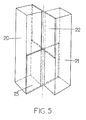
- la figure 5 est une vue en perspective montrant une réalisation possible des axes du parallélogramme articulé.
- Sur la figure 1, on a référencé 1 un disque magnétique, à axe de rotation 2, et qui en réalité pourra être constitué d'un empilage de tels disques, chacun ayant deux faces magnétiques.
- Chacune des faces comporte un certain nombre de zones magnétiques concentriques 3, lesquelles, dans l'exemple représenté, sont au nombre de huit et sont elles mêmes constituées d'un certain nombre de pistes magnétiques circulaires, au nombre de par exemple 60 par zone. Ces pistes peuvent être lues (ou enregistrées) par un ensemble de têtes magnétiques 4, à chaque tête étant affectée une zone magnétique 3 déterminée. Ces têtes sont portées par des patins 5, lesquels peuvent parvenir à une configuration de vol stable à très faible distance de la surface du disque lorsque celui-ci tourne à vitesse élevée (de l'ordre de 3 600 t/mn) le patin étant spécialement configuré à cet effet, et ceci de façon connue en soi.
- Comme mieux visible sur la figure 2, les têtes magnétiques 4 sont disposées à proximité du "bord de fuite" 6 des patins 5, le disque tournant dans le sens de la flèche 7.
- Le patin 5 representé (comme chacun des trois autres patins 5, lesquels ne sont pas visibles sur cette figure) porte deux têtes magnétiques 4 radialement espacées de telle sorte que lorsque l'une d'elles se situe à proximité du bord périphérique extérieur d'une des zones 3, l'autre se situe à proximité du bord périphérique extérieur de la zone 3 voisine. En d'autres termes, chaque patin 5, portant deux têtes magnétiques 4, intéresse deux zones magnétiques voisines 3 du disque 1; comme indiqué plus haut, chaque tête 4 est affectée à une seule zone 3. A aucun moment une tête ne peut explorer une piste à laquelle elle n'a pas été affectée, ce qui conduit à une optimisation de l'exploitation des surfaces magnétiques du disque.
- Dès lors, on voit que grâce à cette disposition il suffira de déplacer radialement un patin 5 pour avoir rapidement accès, par l'une ou par l'autre des têtes 4, à l'ensemble des informations portées par les deux zones magnétiques voisines 3.
- Pour ce faire, le patin 5 n'aura à se déplacer radialement que sur une distance maximale correspondant à la largeur d'une seule zone 3. On voit de quelle façon très simple l'invention permet de raccourcir le temps d'accès t1 aux pistes intéressées des zones 3.
- Un aspect essentiel de la présente invention concerne, comme indiqué plus haut, le positionneur, à savoir l'ensemble des moyens électriques et mécaniques qui permettront d'amener une tête déterminée sur la piste qu'elle doit lire, et ceci, par exemple, par un mouvement d'ensemble des patins 5, lesquels, dans un but de simplification, peuvent être portés par le même support.
- Ce support a été référencé en 8 sur la figure 1.
- Les quatre patins 5 sont reliés à ce support 8 par des ressorts porte-patins 9.
- Le moteur électrodynamique a été référencé en 10. Par un bras principal 11 articulé à une partie fixe 16 autour d'un axe 12 parallèle à l'axe 2, l'organe mobile de ce moteur, à savoir la bobine 10 (située dans le champ magnétique d'un aimant permanent 13), est reliée à un bras porte-têtes 14 auquel est fixé le support précité 8. La liaison entre le bras principal 11 et le bras porte-têtes 14 est réalisée par l'intermédiaire d'un axe 15 parallèle à l'axe 12. Un bras secondaire 17 relie par ailleurs la partie fixe 16 au bras 14 par l'intermédiaire de deux autres axes 18 et 19 parallèles aux axes 12 et 15 et formant avec ceux-ci un parallélogramme articulé 11-16-17-14.
- Ainsi, on conçoit que grâce à cette disposition on pourra obtenir un déplacement pratiquement radial du bras 14 et donc des patins 5 lors du pivotement du bras principal 11 autour de l'axe 12, lorsque le moteur 10 est excité, et ceci avec d'excellentes possibilités de compensation du système vis à vis des vibrations et des chocs, grâce à l'équilibrage des masses mobiles ainsi réalisé par rapport à l'axe 12.
- Etant donné les très faibles débattements angulaires du bras principal 11, de l'ordre de 2,5°, il n'est pas possible d'utiliser des roulements à billes ou analogues au niveau des axis 12-15-18-19 du parallélogramme déformable, car ces roulements ne seraient pas suffisamment lubrifiants et risqueraient rapidement de de détériorer.
- C'est pourquoi on utilisera de préférence des articulations à lames flexibles telles que celle qui est représentée à titre d'exemple sur la figure 5.
- Etant donné deux pièces de support rigides 20 et 21 Fixées sur les organes à relier, (voir également figure 1), on les relie par deux lames flexibles 22 et 23 se situant au repos dans deux plans orthogonaux dont l'intersection se trouve être l'axe de la rotation d'un support rigide 20 ou 21 par rapport à l'autre, lorsque les lames fléchissent. On obtient ainsi une excellente articulation, qui au surplus est à rappel élastique automatique dans sa position neutre, et qui présente un minimum de frottements et aucun risque de grippage. En outre, ce type d'articulation présente une grande rigidité vis-à-vis d'efforts autres que le couple de rotation, et aucun jeu.
Claims (3)
Applications Claiming Priority (2)
| Application Number | Priority Date | Filing Date | Title |
|---|---|---|---|
| FR8512719 | 1985-08-26 | ||
| FR8512719A FR2586495B1 (fr) | 1985-08-26 | 1985-08-26 | Agencement de tetes magnetiques d'enregistrement et/ou de lecture pour memoires a disques |
Publications (2)
| Publication Number | Publication Date |
|---|---|
| EP0214052A1 EP0214052A1 (fr) | 1987-03-11 |
| EP0214052B1 true EP0214052B1 (fr) | 1991-05-15 |
Family
ID=9322383
Family Applications (1)
| Application Number | Title | Priority Date | Filing Date |
|---|---|---|---|
| EP86401880A Expired - Lifetime EP0214052B1 (fr) | 1985-08-26 | 1986-08-26 | Agencement de têtes magnétiques d'enregistrement et/ou de lecture pour mémoires à disques |
Country Status (4)
| Country | Link |
|---|---|
| US (1) | US4751596A (fr) |
| EP (1) | EP0214052B1 (fr) |
| DE (1) | DE3679262D1 (fr) |
| FR (1) | FR2586495B1 (fr) |
Families Citing this family (8)
| Publication number | Priority date | Publication date | Assignee | Title |
|---|---|---|---|---|
| US5202804A (en) * | 1990-05-18 | 1993-04-13 | Kabushiki Kaisha Toshiba | Magnetic disk drive with a magnetic head rotationally actuated |
| US6963472B2 (en) * | 2000-08-30 | 2005-11-08 | Seagate Technology Llc | Flexural pivot for rotary disc drive actuator |
| US7072147B2 (en) * | 2003-06-20 | 2006-07-04 | Seagate Technology Llc | Hard drive actuator arm with reduced skew variation |
| GR20130100475A (el) * | 2013-08-16 | 2015-03-18 | Κωνσταντινος Γεωργιου Κογιας | Περιστροφικη εκμεταλλευση των σκληρων δισκων |
| US10431246B2 (en) * | 2016-12-15 | 2019-10-01 | Seagate Technology Llc | Dual actuator storage device utilizing multiple disk zones |
| US10366726B1 (en) | 2018-03-29 | 2019-07-30 | Seagate Technology Llc | Interlaced magnetic recording in with multiple independent-actuators having respective independent heads |
| US10510373B1 (en) | 2018-03-29 | 2019-12-17 | Seagate Technology Llc | Multiple-actuator drive with separate, radially-defined, zones having reduced skew and/or different track properties |
| US10482911B1 (en) | 2018-08-13 | 2019-11-19 | Seagate Technology Llc | Multiple-actuator drive that provides duplication using multiple volumes |
Family Cites Families (9)
| Publication number | Priority date | Publication date | Assignee | Title |
|---|---|---|---|---|
| US3170149A (en) * | 1961-10-04 | 1965-02-16 | Data Products Corp | Transducer |
| NL7612401A (nl) * | 1976-11-09 | 1978-05-11 | Philips Nv | Elektrisch bestuurbare draagarminrichting. |
| JPS5412712A (en) * | 1977-06-24 | 1979-01-30 | Nec Corp | Magnetic disc apparaatus |
| JPS551620A (en) * | 1978-06-20 | 1980-01-08 | Fujitsu Ltd | Multi-head |
| JPS5584028A (en) * | 1978-12-20 | 1980-06-24 | Fujitsu Ltd | Positioning mechanism of magnetic head |
| JPS55101165A (en) * | 1979-01-22 | 1980-08-01 | Nec Corp | Magnetic head movable arm assembling |
| JPS59144023A (ja) * | 1983-02-07 | 1984-08-17 | Seiko Epson Corp | 磁気ヘツド |
| US4631611A (en) * | 1983-09-06 | 1986-12-23 | Digital Equipment Corporation | Read/write head positioner arrangement |
| JPS6069867A (ja) * | 1983-09-22 | 1985-04-20 | Sharp Corp | 磁気ディスク記録再生装置 |
-
1985
- 1985-08-26 FR FR8512719A patent/FR2586495B1/fr not_active Expired
-
1986
- 1986-08-25 US US06/899,686 patent/US4751596A/en not_active Expired - Fee Related
- 1986-08-26 EP EP86401880A patent/EP0214052B1/fr not_active Expired - Lifetime
- 1986-08-26 DE DE8686401880T patent/DE3679262D1/de not_active Expired - Lifetime
Non-Patent Citations (6)
| Title |
|---|
| PATENTS ABSTRACTS OF JAPAN, vol. 3, no. 34 (E-99), 22 mars 1979, page 94 E 99; & JP-A-54 12 712 (NIPPON DENKI K.K.) 30-01-1979 * |
| PATENTS ABSTRACTS OF JAPAN, vol. 4, no. 131 (P-27)[613], 13 septembre 1980; & JP-A-55 84 028 (FUJITSU K.K.) 24-06-1980 * |
| PATENTS ABSTRACTS OF JAPAN, vol. 4, no. 153 (P-33)[635], 25 octobre 1980; & JP-A-55 101 165 (NIPPON DENKI K.K.) 01-08-1980 * |
| PATENTS ABSTRACTS OF JAPAN, vol. 4, no. 27 (P-1)[509], 7 mars 1980; & JP-A-55 1620 (FUJITSU K.K.) 08-01-1980 * |
| PATENTS ABSTRACTS OF JAPAN, vol. 8, no. 278 (P-322)[1715], 19 décembre 1984; & JP-A-59 144 023 (SUWA SEIKOSHA K.K.) 17-08-1984 * |
| PATENTS ABSTRACTS OF JAPAN, vol. 9, no. 207 (P-382)[1930], 24 août 1985; & JP-A-60 69 867 (SHARP K.K.) 20-04-1985 * |
Also Published As
| Publication number | Publication date |
|---|---|
| FR2586495A1 (fr) | 1987-02-27 |
| US4751596A (en) | 1988-06-14 |
| FR2586495B1 (fr) | 1988-09-16 |
| EP0214052A1 (fr) | 1987-03-11 |
| DE3679262D1 (de) | 1991-06-20 |
Similar Documents
| Publication | Publication Date | Title |
|---|---|---|
| EP0668130B1 (fr) | Dispositif manipulateur, à structure parallèle, pour déplacer et orienter un objet dans un espace de travail cylindrique | |
| EP2763859B1 (fr) | Roue omnidirectionnelle motorisable et vehicule qui en est equipe | |
| EP2155553B1 (fr) | Dispositif de commande de pales d'helicoptere ou similaire | |
| EP0642119B1 (fr) | Patin de vol à profil perfectionné | |
| FR2579338A1 (fr) | Dispositif de commande de position sur deux axes | |
| FR2768997A1 (fr) | Dispositif a plateaux cycliques de commande du pas des pales d'un rotor avec piste et doigt d'arret du plateau non tournant | |
| FR2768996A1 (fr) | Dispositif a plateaux cycliques de commande du pas des pales d'un rotor avec entraineur de plateau tournant | |
| EP0266262B1 (fr) | Frein multidisques | |
| EP0222647B1 (fr) | Dispositif de relevage de patins porte-têtes magnétiques d'enregistrement et/ou de lecture, dans un appareil à mémoire à disques | |
| US20040257710A1 (en) | Hard drive actuator arm with reduced skew variation | |
| JP2980583B2 (ja) | ディスクのチルト調整装置 | |
| EP0214052A1 (fr) | Agencement de têtes magnétiques d'enregistrement et/ou de lecture pour mémoires à disques | |
| EP0932151A3 (fr) | Dispositif de fixation de support d'enregistrement et appareil d'entrainement de disque | |
| WO2021001570A1 (fr) | Roue transformable adaptée pour franchir des escaliers et robot autonome équipé d'au moins une telle roue | |
| FR2771708A1 (fr) | Dispositif a plateaux cycliques de commande du pas des pales d'un rotor avec organes guides rotatifs sur coulisseaux translates selon l'axe du rotor | |
| EP0275747B1 (fr) | Tête d'écriture magnétique et de lecture optique d'un support d'informations | |
| EP0165129A1 (fr) | Dispositif d'équilibrage des forces de pesanteur dans un bras robotique | |
| EP0491613B1 (fr) | Dispositif manipulateur pour déplacer un objet, dans l'espace, parallèlement à lui-même | |
| US5151836A (en) | Disk chucking device | |
| FR2597251A1 (fr) | Appareil a disque magnetique | |
| FR2490048A1 (fr) | Unite de commande de tete video | |
| FR2600452A1 (fr) | Appareil a disque magnetique | |
| EP0291398B1 (fr) | Commutateur électrique pour l'alimentation des indicateurs de changement de direction d'un véhicule automobile | |
| JP2003514325A (ja) | 駆動装置及びマイクロアクチュエータによって変換ヘッドの位置決めをするデバイス | |
| FR2749696A1 (fr) | Assemblage rotatif de precision pour memoire a disque |
Legal Events
| Date | Code | Title | Description |
|---|---|---|---|
| PUAI | Public reference made under article 153(3) epc to a published international application that has entered the european phase |
Free format text: ORIGINAL CODE: 0009012 |
|
| 17P | Request for examination filed |
Effective date: 19861222 |
|
| AK | Designated contracting states |
Kind code of ref document: A1 Designated state(s): BE DE GB IT |
|
| 17Q | First examination report despatched |
Effective date: 19880613 |
|
| ITF | It: translation for a ep patent filed | ||
| GRAA | (expected) grant |
Free format text: ORIGINAL CODE: 0009210 |
|
| AK | Designated contracting states |
Kind code of ref document: B1 Designated state(s): BE DE GB IT |
|
| GBT | Gb: translation of ep patent filed (gb section 77(6)(a)/1977) | ||
| REF | Corresponds to: |
Ref document number: 3679262 Country of ref document: DE Date of ref document: 19910620 |
|
| PLBE | No opposition filed within time limit |
Free format text: ORIGINAL CODE: 0009261 |
|
| STAA | Information on the status of an ep patent application or granted ep patent |
Free format text: STATUS: NO OPPOSITION FILED WITHIN TIME LIMIT |
|
| 26N | No opposition filed | ||
| PGFP | Annual fee paid to national office [announced via postgrant information from national office to epo] |
Ref country code: DE Payment date: 19940730 Year of fee payment: 9 |
|
| PGFP | Annual fee paid to national office [announced via postgrant information from national office to epo] |
Ref country code: GB Payment date: 19940819 Year of fee payment: 9 |
|
| PGFP | Annual fee paid to national office [announced via postgrant information from national office to epo] |
Ref country code: BE Payment date: 19940909 Year of fee payment: 9 |
|
| PG25 | Lapsed in a contracting state [announced via postgrant information from national office to epo] |
Ref country code: GB Effective date: 19950826 |
|
| PG25 | Lapsed in a contracting state [announced via postgrant information from national office to epo] |
Ref country code: BE Effective date: 19950831 |
|
| BERE | Be: lapsed |
Owner name: SOC. D'APPLICATIONS GENERALES D'ELECTRICITE ET DE Effective date: 19950831 |
|
| GBPC | Gb: european patent ceased through non-payment of renewal fee |
Effective date: 19950826 |
|
| PG25 | Lapsed in a contracting state [announced via postgrant information from national office to epo] |
Ref country code: DE Effective date: 19960501 |
|
| PG25 | Lapsed in a contracting state [announced via postgrant information from national office to epo] |
Ref country code: IT Free format text: LAPSE BECAUSE OF NON-PAYMENT OF DUE FEES;WARNING: LAPSES OF ITALIAN PATENTS WITH EFFECTIVE DATE BEFORE 2007 MAY HAVE OCCURRED AT ANY TIME BEFORE 2007. THE CORRECT EFFECTIVE DATE MAY BE DIFFERENT FROM THE ONE RECORDED. Effective date: 20050826 |