EP0214054A1 - Kümpelverfahren zum Herstellen steifer Metallteile zur Bildung von Wärmeschutzbekleidungen von Rohren, Ummantelungen und dergleichen - Google Patents
Kümpelverfahren zum Herstellen steifer Metallteile zur Bildung von Wärmeschutzbekleidungen von Rohren, Ummantelungen und dergleichen Download PDFInfo
- Publication number
- EP0214054A1 EP0214054A1 EP86401893A EP86401893A EP0214054A1 EP 0214054 A1 EP0214054 A1 EP 0214054A1 EP 86401893 A EP86401893 A EP 86401893A EP 86401893 A EP86401893 A EP 86401893A EP 0214054 A1 EP0214054 A1 EP 0214054A1
- Authority
- EP
- European Patent Office
- Prior art keywords
- punch
- parts
- produced
- shape
- metal
- Prior art date
- Legal status (The legal status is an assumption and is not a legal conclusion. Google has not performed a legal analysis and makes no representation as to the accuracy of the status listed.)
- Granted
Links
Images



Classifications
-
- B—PERFORMING OPERATIONS; TRANSPORTING
- B21—MECHANICAL METAL-WORKING WITHOUT ESSENTIALLY REMOVING MATERIAL; PUNCHING METAL
- B21D—WORKING OR PROCESSING OF SHEET METAL OR METAL TUBES, RODS OR PROFILES WITHOUT ESSENTIALLY REMOVING MATERIAL; PUNCHING METAL
- B21D22/00—Shaping without cutting, by stamping, spinning, or deep-drawing
- B21D22/02—Stamping using rigid devices or tools
-
- B—PERFORMING OPERATIONS; TRANSPORTING
- B21—MECHANICAL METAL-WORKING WITHOUT ESSENTIALLY REMOVING MATERIAL; PUNCHING METAL
- B21C—MANUFACTURE OF METAL SHEETS, WIRE, RODS, TUBES, PROFILES OR LIKE SEMI-MANUFACTURED PRODUCTS OTHERWISE THAN BY ROLLING; AUXILIARY OPERATIONS USED IN CONNECTION WITH METAL-WORKING WITHOUT ESSENTIALLY REMOVING MATERIAL
- B21C37/00—Manufacture of metal sheets, rods, wire, tubes, profiles or like semi-manufactured products, not otherwise provided for; Manufacture of tubes of special shape
- B21C37/06—Manufacture of metal sheets, rods, wire, tubes, profiles or like semi-manufactured products, not otherwise provided for; Manufacture of tubes of special shape of tubes or metal hoses; Combined procedures for making tubes, e.g. for making multi-wall tubes
- B21C37/15—Making tubes of special shape; Making tube fittings
- B21C37/28—Making tube fittings for connecting pipes, e.g. U-pieces
- B21C37/286—Making tube fittings for connecting pipes, e.g. U-pieces starting from sheet material
Definitions
- the present invention relates to a method of manufacturing by stamping rigid metal parts intended to constitute thermal insulation coatings for pipes, sheaths, and other assimilable members.
- the invention also relates to the parts produced by this method.
- a third method consists, starting from a thin sheet rolled into a cylinder, of making folds on one side to give a progressive bending.
- Elbows for stove pipes are made this way, but the ratio is important and these elbows cannot be oriented cylinder to fit onto the insulation of a curved pipe.
- a thin sheet is stamped in the traditional way, with punch and die, to form two half-bends of rounded shape; the metal used is aluminum, the parts are very thin, elastic, and have insufficient rigidity.
- the use of dies makes tools extremely expensive.
- the present invention aims to remedy these drawbacks of the known technique by proposing a method of manufacturing by stamping rigid metal parts intended to constitute heat-insulating coatings for pipes of sheaths and other assimilable organs, which requires inexpensive tools which can be easily suitable for the farms to be produced, this method therefore making it possible to manufacture such parts of improved quality, at a lower cost than that of known methods.
- the subject of the invention is a method of manufacturing by stamping rigid metal parts intended to constitute thermal insulation coatings for pipes, sheaths, and the like, characterized in that a metal plate is stamped , without matrix, using an appropriately shaped punch and a flat support cut to the shape of the contour of the part to be produced in projection on a plane parallel to the support the punch being moved in conditions suitable for producing an elongation combined with a controlled sliding of said plate between support and clamps.
- said metal plate can be clamped at the periphery of the cutout of said support, by pinching between the latter and a sidewall, and the movement of the punch can be modulated so that the resulting part exactly matches the shape of the entire punch or only a part thereof.
- the pinching will be modulated so as to allow a certain sliding of the plate.
- the fallen edges resulting from the stamping operation can possibly be removed.
- the punch may have any desired shape corresponding to that of the part to be formed. It may be monobloc, solid (machined or molded) or hollowed out (mechanically welded), but, in a preferred embodiment of the invention, the punch will result from the end-to-end juxtaposition and the assembly of elementary parts of corresponding shape to longitudinal sections of the workpiece. Said elementary parts will preferably be cylinder portions, with an elliptical or polygonal circular section, but they may possibly have plane surfaces. They will be arranged end to end along flat faces corresponding to cross sections of the part to be produced, each part being made integral with the plate of a stamping press by means usual in the art. The junction of the elementary parts will generate sharp edges, which will give rigidity to the formed part and allow a better distribution of the lengthening of the sheet, thus reducing the risks, existing in other systems, of constituting zones of too small thickness.
- Each part having a shape corresponding substantially to that of a section of the part it will thus be easy, by having a sufficient set of elementary parts and by joining them end to end, to make punches of complex shape adapted to the shape of the desired part, without having to make an individual stamping punch for each part. This will result in significant time savings and a considerably reduced cost of manufacturing the parts. metallic.
- the device represented in FIG. 1 comprises a plate 1 for a stamping press, on the underside of which is fixed, by means of bolts 2, a stamping punch generally having a U-shaped cross section, which is designated by the general reference 3.
- the plate 1 moves under the stress of a jack in line with a fixed support frame 4, supporting a sheet metal plate 5 intended to be shaped to the profile of the desired part.
- openings, respectively 8 and 9 for the passage of the punch 3, these openings having a profile complementary to that of the punch in the support plane.
- the sheet metal plate to be stamped 5 being held in position on the support 4 by the sidewall clamp 6, the punch 3 is lowered with a controlled speed, so as to cause a combined elongation and displacement of the metal that the plate 5, in a manner known per se, so as to cause the plate 5 to conform to the shape of the punch by deformation, without using a matrix.
- the stroke of the piston can be modulated as a function of the desired result, that is to say depending on whether one wishes the deformed sheet to conform to the exact shape of the punch 3 or its lower part simply.
- the edges of the deformed part, kept pinched between the support frame and the sidewall can then be removed or cut appropriately to form these fallen edges.
- the punch of the stamping press can be mcno- block and be made by machining or molding metal (cast iron, aluminum alloy etc ...), cement concrete or synthetic concrete (polyester resin, epoxy or other, mixed with aggregates). It may also be hollow and filled with a filling material.
- a composite punch consisting of removable elementary parts, of advantage, will be used.
- cylindrical such as 3a and 3b in the case of FIG. 1, each of which has a shape which matches that of a section of the part with a U-shaped section.
- the elementary parts of the punch being removable, it will also be possible to produce, from a sufficient clearance of such parts, of various shapes and sizes, punches of extremely different shapes adapted to the desired profile.
- Figures 5 to 11 illustrate bent parts made from such composite punches.
- We see see (see Figure 9, for example) that it is possible to make elbows whose profile approaches very close to a curvilinear profile.
- elementary parts of identical punch can be juxtaposed with different parts to form punches making it possible to obtain bent parts, of which only the portions corresponding to identical parts of the punches, for example the portions 12 of the parts of Figures 6 and 7, have an identical profile.
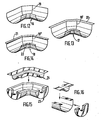
- Figures 12, 13. and 14 are perspective views of bent parts 16, 17 and 18, produced in accordance with the invention with punches consisting of three elementary parts. As can be seen, edges such as 19, 19 ′ and 19 "appear at the joint planes of the elementary parts of the punches, but these edges, far from constituting a drawback, act as so many transverse mechanical reinforcements.
- FIG. 15 illustrates the application of the invention to the manufacture of a double-walled elbow element intended to contain a heat-insulating material in order to isolate a pipe elbow.
- the hollow part 23 intended to contain the heat-insulating material and the cover 24 covering the piping are produced in accordance with the invention.
- FIG. 15 illustrates an embodiment analogous to that of FIG. 15, in which the part 25 containing the insulation is capped by the cover 26 and is closed at its end by an attached bottom.
- the invention is not limited, of course, to the production of such parts.
- FIGS. 17, 18 and 19 illustrate the application of the method according to the invention to the production of a tee 28 (FIG. 17) using a punch 29 consisting of three elementary parts 29a, 29b and 29c (Figure 18), passing through a cutout 30 in the support frame ( Figure 19). Tee-shaped double pieces walls, intended to contain a thermal insulator, which can of course be produced by the process according to the invention.
- flange covers comprising two U-shaped sections 31 (figure 20), 32 (figure 21) and 33 (figure 22), can also be produced by the process according to the invention, as well as various types of valve covers with two U-shaped parts 34 (figure 23), 35 (figure 24) or 36 (figure 25).
- the process according to the invention therefore lends itself to easy and inexpensive manufacture of multiple metal parts of common use in the technique of thermal insulation, ventilation and other activities.
- the parts thus produced may include double walls and be used for thermal insulation of various components. They may include an integrated thermal insulator which matches their shape and that of the member to be insulated.
Landscapes
- Engineering & Computer Science (AREA)
- Mechanical Engineering (AREA)
- Shaping Metal By Deep-Drawing, Or The Like (AREA)
- Bending Of Plates, Rods, And Pipes (AREA)
- Perforating, Stamping-Out Or Severing By Means Other Than Cutting (AREA)
- Punching Or Piercing (AREA)
- Heat Treatments In General, Especially Conveying And Cooling (AREA)
- Other Surface Treatments For Metallic Materials (AREA)
Priority Applications (1)
| Application Number | Priority Date | Filing Date | Title |
|---|---|---|---|
| AT86401893T ATE58315T1 (de) | 1985-08-30 | 1986-08-28 | Kuempelverfahren zum herstellen steifer metallteile zur bildung von waermeschutzbekleidungen von rohren, ummantelungen und dergleichen. |
Applications Claiming Priority (2)
| Application Number | Priority Date | Filing Date | Title |
|---|---|---|---|
| FR8512966 | 1985-08-30 | ||
| FR8512966A FR2586597B1 (fr) | 1985-08-30 | 1985-08-30 | Procede de fabrication par emboutissage de pieces metalliques rigides destinees a constituer des revetements de calorifuge de tuyauteries, des gaines et d'autres organes similaires |
Publications (2)
| Publication Number | Publication Date |
|---|---|
| EP0214054A1 true EP0214054A1 (de) | 1987-03-11 |
| EP0214054B1 EP0214054B1 (de) | 1990-11-14 |
Family
ID=9322516
Family Applications (1)
| Application Number | Title | Priority Date | Filing Date |
|---|---|---|---|
| EP86401893A Expired - Lifetime EP0214054B1 (de) | 1985-08-30 | 1986-08-28 | Kümpelverfahren zum Herstellen steifer Metallteile zur Bildung von Wärmeschutzbekleidungen von Rohren, Ummantelungen und dergleichen |
Country Status (5)
| Country | Link |
|---|---|
| EP (1) | EP0214054B1 (de) |
| AT (1) | ATE58315T1 (de) |
| DE (1) | DE3675610D1 (de) |
| ES (1) | ES2001765A6 (de) |
| FR (1) | FR2586597B1 (de) |
Cited By (1)
| Publication number | Priority date | Publication date | Assignee | Title |
|---|---|---|---|---|
| EP0510759A1 (de) * | 1991-04-26 | 1992-10-28 | AP&T Automation & Tooling AB | Verfahren zur Herstellung von dünnwandigen Rohrkrümmern |
Citations (6)
| Publication number | Priority date | Publication date | Assignee | Title |
|---|---|---|---|---|
| DE284081C (de) * | ||||
| DE310993C (de) * | ||||
| US1678744A (en) * | 1927-05-21 | 1928-07-31 | Western Metal Specialty Co | Method of making pipe elbows |
| FR785375A (fr) * | 1935-02-07 | 1935-08-08 | Decauville Aine Soc Nouv Ets | Nouveau procédé d'emboutissage, machine pour son application et pièces embouties obtenues |
| FR798402A (fr) * | 1935-11-29 | 1936-05-16 | Cie Ind D App Radio Electr | Perfectionnements à la fabrication des raccords pour tubes et canalisations |
| FR2166158A1 (de) * | 1971-12-29 | 1973-08-10 | Combustion Eng |
Family Cites Families (1)
| Publication number | Priority date | Publication date | Assignee | Title |
|---|---|---|---|---|
| DE289081C (de) * |
-
1985
- 1985-08-30 FR FR8512966A patent/FR2586597B1/fr not_active Expired - Fee Related
-
1986
- 1986-08-28 DE DE8686401893T patent/DE3675610D1/de not_active Expired - Fee Related
- 1986-08-28 AT AT86401893T patent/ATE58315T1/de not_active IP Right Cessation
- 1986-08-28 EP EP86401893A patent/EP0214054B1/de not_active Expired - Lifetime
- 1986-08-29 ES ES8601483A patent/ES2001765A6/es not_active Expired
Patent Citations (6)
| Publication number | Priority date | Publication date | Assignee | Title |
|---|---|---|---|---|
| DE284081C (de) * | ||||
| DE310993C (de) * | ||||
| US1678744A (en) * | 1927-05-21 | 1928-07-31 | Western Metal Specialty Co | Method of making pipe elbows |
| FR785375A (fr) * | 1935-02-07 | 1935-08-08 | Decauville Aine Soc Nouv Ets | Nouveau procédé d'emboutissage, machine pour son application et pièces embouties obtenues |
| FR798402A (fr) * | 1935-11-29 | 1936-05-16 | Cie Ind D App Radio Electr | Perfectionnements à la fabrication des raccords pour tubes et canalisations |
| FR2166158A1 (de) * | 1971-12-29 | 1973-08-10 | Combustion Eng |
Cited By (1)
| Publication number | Priority date | Publication date | Assignee | Title |
|---|---|---|---|---|
| EP0510759A1 (de) * | 1991-04-26 | 1992-10-28 | AP&T Automation & Tooling AB | Verfahren zur Herstellung von dünnwandigen Rohrkrümmern |
Also Published As
| Publication number | Publication date |
|---|---|
| ATE58315T1 (de) | 1990-11-15 |
| EP0214054B1 (de) | 1990-11-14 |
| ES2001765A6 (es) | 1988-06-16 |
| FR2586597B1 (fr) | 1990-02-02 |
| DE3675610D1 (de) | 1990-12-20 |
| FR2586597A1 (fr) | 1987-03-06 |
Similar Documents
| Publication | Publication Date | Title |
|---|---|---|
| FR2611802A1 (fr) | Echelle et son procede de fabrication | |
| FR2752756A1 (fr) | Equipement pour le formage de profiles metalliques | |
| CH217289A (fr) | Procédé pour la fabrication de tubes flexibles à ondulations, machine pour la mise en oeuvre de ce procédé et tube obtenu par ce procédé. | |
| CA2133283C (fr) | Outil de sertissage pour le raccordement d'un cable electrique dans un element d'extremite | |
| EP0878287A1 (de) | Aufweitungsvorrichtung zum Formen von Muffen an Kunststoff- oder Kunststoff/Aluminium-Rohrenden | |
| FR2475945A1 (fr) | Procede de preparation des bords de la tole dans le procede de formage des tubes a la presse dit uo et appareil pour sa mise en oeuvre | |
| EP0214054B1 (de) | Kümpelverfahren zum Herstellen steifer Metallteile zur Bildung von Wärmeschutzbekleidungen von Rohren, Ummantelungen und dergleichen | |
| EP0433203B1 (de) | Verfahren und Vorrichtung zum Tiefziehen von konischen Behältern und nach diesem Verfahren hergestellter Behälter | |
| EP2245206A1 (de) | Verfahren zur herstellung eines keramikfaserverstärkten metallteils | |
| LU82892A1 (fr) | Procede et dispositif pour le formage de tubes coudes a partir d'elements de tubes rectilignes | |
| CA2449005A1 (fr) | Procede de fabrication de profiles metalliques | |
| FR2798314A1 (fr) | Presse radiale pour le sertissage de flexibles a haute pression sur des corps de raccords creux, symetriques de revolution | |
| WO2014135772A1 (fr) | Outil pour former une collerette a une extremite d'un tube | |
| FR2655890A1 (fr) | Procede d'elaboration d'une piece de forme non developpable a partir d'un flan de tole et piece de forme obtenue par ce procede. | |
| EP0517572B2 (de) | Verfahren zur Herstellung einer Riemenscheibe, Vorrichtung zu ihrer Herstellung und so hergestellte Riemenscheibe | |
| FR2659579A1 (fr) | Procede de fabrication d'element creux et de recipient metalliques de forme troncopyramidale et element creux et recipient metalliques de forme troncopyramidale. | |
| EP0705404B1 (de) | Metallteil mit einem element das eine kugelwand hat, verfahren zur herstellung des metallteiles und kugelkupplung für eine abgasvorrichtung | |
| FR2518014A1 (fr) | Procede et dispositif pour la realisation d'une conduite souple coudee | |
| EP1200245B1 (de) | Verfahren zur herstellung eines u-förmigen profils für eine kabelrinne, und danach hergestelltes profil | |
| FR2510919A1 (fr) | Perfectionnements aux procedes et dispositifs de fabrication des armatures annulaires pour joints d'etancheite et aux armatures et joints correspondants | |
| FR2863187A1 (fr) | Procede de fabrication d'une poulie d'entrainement et poulie realisee selon ce procede | |
| EP1709344B1 (de) | Vorrichtung zur verbindung von zwei kabeln während der herstellung der maschen eines sicherheitsnetzes | |
| FR2696958A1 (fr) | Procédé de fabrication d'un rouleau de convoyeur et équipement de mise en Óoeuvre du procédé. | |
| EP0124152A1 (de) | Vorrichtungen zum Zusammenfügen von Hohlkörpern durch Falzen | |
| FR2504416A1 (fr) | Procede et appareil pour fabriquer des coudes de tube par emboutissage profond a partir d'un flan |
Legal Events
| Date | Code | Title | Description |
|---|---|---|---|
| PUAI | Public reference made under article 153(3) epc to a published international application that has entered the european phase |
Free format text: ORIGINAL CODE: 0009012 |
|
| AK | Designated contracting states |
Kind code of ref document: A1 Designated state(s): AT BE CH DE GB IT LI LU NL SE |
|
| 17P | Request for examination filed |
Effective date: 19870603 |
|
| 17Q | First examination report despatched |
Effective date: 19880824 |
|
| GRAA | (expected) grant |
Free format text: ORIGINAL CODE: 0009210 |
|
| ITF | It: translation for a ep patent filed | ||
| AK | Designated contracting states |
Kind code of ref document: B1 Designated state(s): AT BE CH DE GB IT LI LU NL SE |
|
| REF | Corresponds to: |
Ref document number: 58315 Country of ref document: AT Date of ref document: 19901115 Kind code of ref document: T |
|
| REF | Corresponds to: |
Ref document number: 3675610 Country of ref document: DE Date of ref document: 19901220 |
|
| GBT | Gb: translation of ep patent filed (gb section 77(6)(a)/1977) | ||
| ITTA | It: last paid annual fee | ||
| PLBE | No opposition filed within time limit |
Free format text: ORIGINAL CODE: 0009261 |
|
| STAA | Information on the status of an ep patent application or granted ep patent |
Free format text: STATUS: NO OPPOSITION FILED WITHIN TIME LIMIT |
|
| 26N | No opposition filed | ||
| EPTA | Lu: last paid annual fee | ||
| EAL | Se: european patent in force in sweden |
Ref document number: 86401893.2 |
|
| PGFP | Annual fee paid to national office [announced via postgrant information from national office to epo] |
Ref country code: SE Payment date: 19950731 Year of fee payment: 10 |
|
| PGFP | Annual fee paid to national office [announced via postgrant information from national office to epo] |
Ref country code: LU Payment date: 19950801 Year of fee payment: 10 |
|
| PGFP | Annual fee paid to national office [announced via postgrant information from national office to epo] |
Ref country code: AT Payment date: 19950803 Year of fee payment: 10 |
|
| PGFP | Annual fee paid to national office [announced via postgrant information from national office to epo] |
Ref country code: CH Payment date: 19950815 Year of fee payment: 10 |
|
| PGFP | Annual fee paid to national office [announced via postgrant information from national office to epo] |
Ref country code: GB Payment date: 19950817 Year of fee payment: 10 |
|
| PGFP | Annual fee paid to national office [announced via postgrant information from national office to epo] |
Ref country code: NL Payment date: 19950831 Year of fee payment: 10 |
|
| PG25 | Lapsed in a contracting state [announced via postgrant information from national office to epo] |
Ref country code: LU Free format text: LAPSE BECAUSE OF NON-PAYMENT OF DUE FEES Effective date: 19960828 Ref country code: GB Effective date: 19960828 Ref country code: AT Effective date: 19960828 |
|
| PG25 | Lapsed in a contracting state [announced via postgrant information from national office to epo] |
Ref country code: SE Effective date: 19960829 |
|
| PG25 | Lapsed in a contracting state [announced via postgrant information from national office to epo] |
Ref country code: LI Effective date: 19960831 Ref country code: CH Effective date: 19960831 |
|
| PG25 | Lapsed in a contracting state [announced via postgrant information from national office to epo] |
Ref country code: NL Effective date: 19970301 |
|
| REG | Reference to a national code |
Ref country code: CH Ref legal event code: PL |
|
| GBPC | Gb: european patent ceased through non-payment of renewal fee |
Effective date: 19960828 |
|
| NLV4 | Nl: lapsed or anulled due to non-payment of the annual fee |
Effective date: 19970301 |
|
| EUG | Se: european patent has lapsed |
Ref document number: 86401893.2 |
|
| PGFP | Annual fee paid to national office [announced via postgrant information from national office to epo] |
Ref country code: BE Payment date: 19990825 Year of fee payment: 14 |
|
| PGFP | Annual fee paid to national office [announced via postgrant information from national office to epo] |
Ref country code: DE Payment date: 19990826 Year of fee payment: 14 |
|
| PG25 | Lapsed in a contracting state [announced via postgrant information from national office to epo] |
Ref country code: BE Free format text: LAPSE BECAUSE OF NON-PAYMENT OF DUE FEES Effective date: 20000831 |
|
| BERE | Be: lapsed |
Owner name: WANNER ISOFI ISOLATION Effective date: 20000831 |
|
| PG25 | Lapsed in a contracting state [announced via postgrant information from national office to epo] |
Ref country code: DE Free format text: LAPSE BECAUSE OF NON-PAYMENT OF DUE FEES Effective date: 20010501 |
|
| PG25 | Lapsed in a contracting state [announced via postgrant information from national office to epo] |
Ref country code: IT Free format text: LAPSE BECAUSE OF NON-PAYMENT OF DUE FEES;WARNING: LAPSES OF ITALIAN PATENTS WITH EFFECTIVE DATE BEFORE 2007 MAY HAVE OCCURRED AT ANY TIME BEFORE 2007. THE CORRECT EFFECTIVE DATE MAY BE DIFFERENT FROM THE ONE RECORDED. Effective date: 20050828 |