EP0214295A1 - Appareil de commande de l'operation de tournage conique d'une machine d'usinage a decharge electrique a fil de coupe - Google Patents
Appareil de commande de l'operation de tournage conique d'une machine d'usinage a decharge electrique a fil de coupe Download PDFInfo
- Publication number
- EP0214295A1 EP0214295A1 EP86901139A EP86901139A EP0214295A1 EP 0214295 A1 EP0214295 A1 EP 0214295A1 EP 86901139 A EP86901139 A EP 86901139A EP 86901139 A EP86901139 A EP 86901139A EP 0214295 A1 EP0214295 A1 EP 0214295A1
- Authority
- EP
- European Patent Office
- Prior art keywords
- wire
- wire electrode
- guide
- angle
- deviation
- Prior art date
- Legal status (The legal status is an assumption and is not a legal conclusion. Google has not performed a legal analysis and makes no representation as to the accuracy of the status listed.)
- Granted
Links
Images


Classifications
-
- B—PERFORMING OPERATIONS; TRANSPORTING
- B23—MACHINE TOOLS; METAL-WORKING NOT OTHERWISE PROVIDED FOR
- B23K—SOLDERING OR UNSOLDERING; WELDING; CLADDING OR PLATING BY SOLDERING OR WELDING; CUTTING BY APPLYING HEAT LOCALLY, e.g. FLAME CUTTING; WORKING BY LASER BEAM
- B23K7/00—Cutting, scarfing, or desurfacing by applying flames
- B23K7/06—Machines, apparatus or equipment specially designed for scarfing or desurfacing
-
- B—PERFORMING OPERATIONS; TRANSPORTING
- B23—MACHINE TOOLS; METAL-WORKING NOT OTHERWISE PROVIDED FOR
- B23H—WORKING OF METAL BY THE ACTION OF A HIGH CONCENTRATION OF ELECTRIC CURRENT ON A WORKPIECE USING AN ELECTRODE WHICH TAKES THE PLACE OF A TOOL; SUCH WORKING COMBINED WITH OTHER FORMS OF WORKING OF METAL
- B23H7/00—Processes or apparatus applicable to both electrical discharge machining and electrochemical machining
- B23H7/02—Wire-cutting
- B23H7/06—Control of the travel curve of the relative movement between electrode and workpiece
- B23H7/065—Electric circuits specially adapted therefor
Definitions
- the present invention relates to a taper cutting control unit for a wire-cut, electric discharge machine.
- a wire-cut, electric discharge machine has a wire electrode (hereinafter referred to simply as a wire) stretched in a taut condition between upper and lower guides and cuts a workpiece by a discharge which is produced between the wire and the workpiece.
- the workpiece is fixedly mounted on a table and shifted along a desired shape in the X and Y directions in response to commands from a numerical controller.
- the wire is stretched in a direction perpendicular to the table (or the workpiece), the workpiece is cut into a required profile whose top and bottom surfaces have the same shape.
- taper cutting takes place by which the workpiece is cut into a required profile with top and bottom surfaces of different shapes.
- Fig. 8 is a schematic diagram showing the general arrangement of such a four-axis control wire-cut, electric discharge machine, in which a workpiece WK is fixedly mounted on an X-Y table TB which is driven by motors MX and MY in the X and Y directions.
- a wire WR is paid out of a reel RL1 and wound onto a reel RL2 while being stretched between lower and upper guides DG and UG, and a voltage is applied from a contact electrode, not shown, to the wire, producing a discharge between it and the workpiece WR.
- the upper guide UG is provided on a column CM in a manner to be movable by motors MU and MV in the X and Y directions, respectively, and the- motors MX, MY, MU and MV are driven by servo control circuits DVX, DVY, DVU and DVV of a numerical controller NC.
- processing for distributing pulses to each axis is performed by a distribution circuit DS.
- taper cutting of the workpiece WK can be achieved by displacing the upper guide UG in the X and Y directions so that the wire WR is tilted with respect to the workpiece WK.
- Fig. 9 is a diagram explanatory of such taper cutting.
- the wire WR is shown to be stretched between the upper and lower guides UG and DG at a predetermined angle to the workpiece WK.
- a shape, into which the bottom surface PL of the workpiece WK is to be cut is programmed (The shape into which the top surface QU of the workpiece WK is cut may also be programmed)
- the angle of taper be represented by ⁇ 0
- the distance between the upper and lower guides UG and DG by H the distance between the lower guide DG and the bottom surface of the workpiece WK by h
- the amounts of offset d 1 and d 2 of the lower and upper guides DG and UG from the bottom surface PL of the workpiece WK can be expressed as follows: where d is the width of a groove being cut in the workpiece.
- the workpiece can be tapered at the angle 6 0 , as depicted in Fig. 10.
- the broken line and the one-dot chain line indicate paths of the upper and lower guides UG and DG, respectively.
- commands are usually issued on the programmed path on the bottom or top surface of the workpiece, the feed rate along the programmed path, the tapering angle ⁇ 0 , the afore-mentioned distances H and h, etc., thereby performing the cutting as instructed.
- the wire-cut, electric discharge machine usually employs a circularly-bored die for taper cutting.
- Fig. 11 shows in section such circularly-bored dies which are utilized as the upper and lower guides UG and DG.
- reference character CH indicates a circular bore of the die, NSU a bottleneck portion of the upper guide UG, and NSD a bottleneck, portion of the lower guide DG.
- the bottleneck portion of each guide is formed at an acute angle or slightly rounded.
- the amount of travel of the upper guide UG relative to the workpiece is determined regarding the centers of the bottleneck portions NSU and NSD (indicated by black circles) as wire supporting points the positions of which determine the tapering angle, and the movement of the upper guide is controlled accordingly That is, the amount of relative travel of the upper guide UG is calculated on the basis of the tapering angle ⁇ 0 which is an angle between a straight line joining the both supporting points and the workpiece, the vertical distance H between the both supporting points, and the distance h between the wire supporting point in the lower guide DG and the bottom surface of the workpiece, and the movement of the upper guide is controlled in accordance with the amount of its relative travel thus obtained.
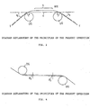
- Fig. 12 is a sectional view for explaining wire guides for taper cutting by the electric discharge machine according, to the above-said proposal.
- reference character WR identifies a wire, UG an upper guide, and DG a lower guide
- a workpiece is disposed between the upper and lower guides UG and DG, though not shown.
- Those portions UGW, UGW' (the upper guide) and DGW, DGW' (the lower guide) of the upper and lower guides UG and DG along which the wire is guided on the said where the workpiece is disposed are each curved, in section, along an arc of a circle with a radius R, and those portions UGU and DGU of the guides which are on the side opposite from the workpiece are conically-sectioned.
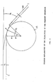
- Fig. 3 is an enlarged diagram of the right half of Fig. 2, showing the state in which the wire WR does not exactly conform to the geometrical configuration of the upper guide UG, owing to the elasticity of the wire; on the side toward the lower guide DG, the wire deviates, by ⁇ 3 , from the line 4 tangential to the both guides and deviates therefrom by ⁇ on the opposite side.
- ⁇ indicates the angle between perpendicular lines from the center of the upper guide UG to the wire WR and the line 4.
- the angle between a perpendicular line from the center of the guide to a line parallel to the direction in which the wire WR is pulled and the perpendicular line to the line 4 is equal to ⁇ 0 .
- the wire WR abruptly bends near the guide and then travels along a substantially straight path (as indicated by 5 in Fig. 2).
- the deviation d 3 of the wire is substantially equal to that in the above case. This is because of the fact that the influence of the direction in which the wire is supported dimi-' nishes as the distance from the guide increases.
- Fig. 5 shows an application of the above discussion to taper cutting.
- the broken line 3 in Fig. 14 shows the results of calculation of the deviation (8 1 + ⁇ 2 ) taking into account the above Eq. (10) as well, and this deviation substantially agrees with the deviation obtained from the experimental results', indicated by the solid line 1.
- the present invention is based upon such principles as mentioned above and is applied to a taper cutting control unit for a wire-cut, electric discharge machine in which a wire is stretched between a pair of guides, each having a curved guideway on the side where a workpiece is disposed, and the wire is held at an angle to the workpiece and displaced relative thereto for taper cutting.
- correcting means for electrically correcting, in accordance with the tapering angle, an error in the inclination angle of the wire which is based on the sum of the first deviation 6 l of the wire supporting point, which is attributable to the curved surface of the guideway, and the second deviation ⁇ 2 of the wire supporting point which is caused by the fact that the wire does not exactly conform to the geometrical configuration of the guideway on account of the elasticity of the wire itself.
- Fig. 1 is a block diagram illustrating the principal part of an example of the numerical control unit of the present invention which conducts electric discharge machining while correcting the vertical distance between the supporting points of the wire.
- reference character PTP indicates a paper tape having numerical control information punched therein TR a tape reader for reading the information punched in the paper tape, DEC a decoder for decoding the information read out of the paper tape PTP, REG a register, and PAR a parameter storage register for storing the tapering angle ⁇ 0 , the distance H between the upper and lower guides, the distance h between the underside of the workpiece and the lower guide, etc.
- Reference character CPS identifies a correction circuit for correcting the distances H and h. The vertical distance between the wire supporting points is corrected on the basis of the following equation:
- Reference character WCP designates a known processing unit which controls wire-cut, electric discharge machining and which inputs position data and parameters such as the tapering angle ⁇ 0 , the distances H and h, and so forth, and calculates and outputs incremental amounts of travel (AX, ⁇ Y) of the workpiece and incremental amounts of travel ( ⁇ U, ⁇ V) of the upper guide.
- the second deviation is given as follows:
Landscapes
- Engineering & Computer Science (AREA)
- Mechanical Engineering (AREA)
- Chemical & Material Sciences (AREA)
- Chemical Kinetics & Catalysis (AREA)
- Electrochemistry (AREA)
- Electrical Discharge Machining, Electrochemical Machining, And Combined Machining (AREA)
Abstract
Applications Claiming Priority (2)
| Application Number | Priority Date | Filing Date | Title |
|---|---|---|---|
| JP24189/85 | 1985-02-09 | ||
| JP60024189A JPS61182729A (ja) | 1985-02-09 | 1985-02-09 | ワイヤカツト放電加工機のテ−パ加工制御装置 |
Publications (3)
| Publication Number | Publication Date |
|---|---|
| EP0214295A1 true EP0214295A1 (fr) | 1987-03-18 |
| EP0214295A4 EP0214295A4 (fr) | 1988-08-29 |
| EP0214295B1 EP0214295B1 (fr) | 1991-09-25 |
Family
ID=12131376
Family Applications (1)
| Application Number | Title | Priority Date | Filing Date |
|---|---|---|---|
| EP86901139A Expired - Lifetime EP0214295B1 (fr) | 1985-02-09 | 1986-02-07 | Appareil de commande de l'operation de tournage conique d'une machine d'usinage a decharge electrique a fil de coupe |
Country Status (5)
| Country | Link |
|---|---|
| US (1) | US4736086A (fr) |
| EP (1) | EP0214295B1 (fr) |
| JP (1) | JPS61182729A (fr) |
| DE (1) | DE3681664D1 (fr) |
| WO (1) | WO1986004532A1 (fr) |
Cited By (3)
| Publication number | Priority date | Publication date | Assignee | Title |
|---|---|---|---|---|
| DE4012530A1 (de) * | 1989-04-19 | 1990-10-25 | Mitsubishi Electric Corp | Elektrische drahtschnittentladungsmaschine |
| EP0742069A3 (fr) * | 1995-05-11 | 1997-10-15 | Charmilles Technologies | Dispositif d'usinage par électroérosion |
| EP0802008A1 (fr) * | 1996-04-10 | 1997-10-22 | AG für industrielle Elektronik AGIE Losone bei Locarno | Procédé pour le découpage par élecroérosion et dispositif approprié |
Families Citing this family (24)
| Publication number | Priority date | Publication date | Assignee | Title |
|---|---|---|---|---|
| DE3715844A1 (de) * | 1986-06-18 | 1987-12-23 | Mitsubishi Electric Corp | Funkenerosionsmaschine mit drahtelektrode |
| JPS6457313A (en) * | 1987-08-27 | 1989-03-03 | Fanuc Ltd | Involute interpolation system |
| JPH0692047B2 (ja) * | 1988-10-05 | 1994-11-16 | ブラザー工業株式会社 | ワイヤ放電加工機のテーパ加工装置 |
| US5051912A (en) * | 1989-02-07 | 1991-09-24 | Hurco Acquisition Corporation | Vectoring/orbiting control unit for electrical discharge machining |
| DE4228330A1 (de) * | 1992-08-26 | 1994-03-10 | Agie Ag Ind Elektronik | Elektroerosions-Schneidvorrichtung und -verfahren |
| US6695848B2 (en) * | 1994-09-02 | 2004-02-24 | Hudson Surgical Design, Inc. | Methods for femoral and tibial resection |
| US8603095B2 (en) | 1994-09-02 | 2013-12-10 | Puget Bio Ventures LLC | Apparatuses for femoral and tibial resection |
| US8062377B2 (en) | 2001-03-05 | 2011-11-22 | Hudson Surgical Design, Inc. | Methods and apparatus for knee arthroplasty |
| US6612043B2 (en) * | 2001-06-08 | 2003-09-02 | Industrial Technology Research Institute | Method and apparatus for vertically calibrating wire of wire cutting electric discharge machine |
| ES2425553T3 (es) * | 2001-09-11 | 2013-10-16 | Agie Charmilles Sa | Procedimiento y dispositivo para la mecanización por electroerosión de alambres múltiples |
| US7815645B2 (en) * | 2004-01-14 | 2010-10-19 | Hudson Surgical Design, Inc. | Methods and apparatus for pinplasty bone resection |
| US7857814B2 (en) * | 2004-01-14 | 2010-12-28 | Hudson Surgical Design, Inc. | Methods and apparatus for minimally invasive arthroplasty |
| US8021368B2 (en) * | 2004-01-14 | 2011-09-20 | Hudson Surgical Design, Inc. | Methods and apparatus for improved cutting tools for resection |
| US20060030854A1 (en) | 2004-02-02 | 2006-02-09 | Haines Timothy G | Methods and apparatus for wireplasty bone resection |
| US8287545B2 (en) | 2004-01-14 | 2012-10-16 | Hudson Surgical Design, Inc. | Methods and apparatus for enhanced retention of prosthetic implants |
| US8114083B2 (en) | 2004-01-14 | 2012-02-14 | Hudson Surgical Design, Inc. | Methods and apparatus for improved drilling and milling tools for resection |
| ATE530283T1 (de) | 2005-03-30 | 2011-11-15 | Agie Charmilles Sa | Verfahren zur vermessung und justierung einer elektrode für eine konusbearbeitung mittels eine schneiddrahtfunkenerosionsmachine |
| JP4919334B2 (ja) * | 2006-07-27 | 2012-04-18 | 株式会社ソディック | ワイヤ電極の設定傾斜角度の測定方法及び測定冶具 |
| JP5271765B2 (ja) * | 2009-03-25 | 2013-08-21 | 株式会社ソディック | ワイヤカット放電加工装置におけるテーパ補正システムおよびテーパ補正方法 |
| JP5088975B2 (ja) * | 2010-10-19 | 2012-12-05 | 株式会社ソディック | ワイヤ放電加工装置 |
| JP4938137B1 (ja) * | 2011-03-03 | 2012-05-23 | ファナック株式会社 | 被加工物の上面検出機能を有するワイヤカット放電加工機 |
| US10189103B2 (en) * | 2013-10-31 | 2019-01-29 | Mitsubishi Electric Corporation | Wire electrical discharge machining apparatus |
| WO2015145529A1 (fr) * | 2014-03-24 | 2015-10-01 | 三菱電機株式会社 | Appareil d'usinage et procédé d'usinage par décharge électrique à fil |
| US10307848B2 (en) * | 2014-11-07 | 2019-06-04 | Hitachi Metals, Ltd. | Electrical discharge machining electrode wire and manufacturing method for same |
Family Cites Families (8)
| Publication number | Priority date | Publication date | Assignee | Title |
|---|---|---|---|---|
| JPS54106994A (en) * | 1978-02-08 | 1979-08-22 | Fanuc Ltd | Machining method for corner papt |
| CH639308A5 (de) * | 1979-04-26 | 1983-11-15 | Agie Ag Ind Elektronik | Verfahren und einrichtung zur orientierung der drahtfuehrungskoepfe an funkenerosiven schneidanlagen zum erodieren mit grosser schraeglage des drahtes. |
| JPS5766823A (en) * | 1980-10-08 | 1982-04-23 | Fanuc Ltd | Wire cutting discharge processing system |
| JPS57166606A (en) * | 1981-04-04 | 1982-10-14 | Fanuc Ltd | Numerical control working method |
| JPS5828424A (ja) * | 1981-08-12 | 1983-02-19 | Fanuc Ltd | 放電加工機のテ−パ加工用ガイド及びテ−パ加工装置 |
| JPS58181105A (ja) * | 1982-04-16 | 1983-10-22 | Fanuc Ltd | 工具径補正方式 |
| JPS5934923A (ja) * | 1982-08-23 | 1984-02-25 | Nissan Motor Co Ltd | 車体パネルのシ−ル構造 |
| JPS60107106A (ja) * | 1983-11-15 | 1985-06-12 | Mitsubishi Electric Corp | 曲線補間装置 |
-
1985
- 1985-02-09 JP JP60024189A patent/JPS61182729A/ja active Granted
-
1986
- 1986-02-07 DE DE8686901139T patent/DE3681664D1/de not_active Expired - Lifetime
- 1986-02-07 US US06/919,004 patent/US4736086A/en not_active Expired - Lifetime
- 1986-02-07 WO PCT/JP1986/000054 patent/WO1986004532A1/fr not_active Ceased
- 1986-02-07 EP EP86901139A patent/EP0214295B1/fr not_active Expired - Lifetime
Non-Patent Citations (3)
| Title |
|---|
| No relevant documents have been disclosed. * |
| Proc.Natl.Acad.Sci. USA, vol. 78, no. 11, November 1981, pp. 6613-6617 * |
| See also references of WO8604532A1 * |
Cited By (4)
| Publication number | Priority date | Publication date | Assignee | Title |
|---|---|---|---|---|
| DE4012530A1 (de) * | 1989-04-19 | 1990-10-25 | Mitsubishi Electric Corp | Elektrische drahtschnittentladungsmaschine |
| EP0742069A3 (fr) * | 1995-05-11 | 1997-10-15 | Charmilles Technologies | Dispositif d'usinage par électroérosion |
| EP0802008A1 (fr) * | 1996-04-10 | 1997-10-22 | AG für industrielle Elektronik AGIE Losone bei Locarno | Procédé pour le découpage par élecroérosion et dispositif approprié |
| US5922220A (en) * | 1996-04-10 | 1999-07-13 | Agie Sa | Method and apparatus for electroerosive cutting |
Also Published As
| Publication number | Publication date |
|---|---|
| WO1986004532A1 (fr) | 1986-08-14 |
| JPH0451285B2 (fr) | 1992-08-18 |
| US4736086A (en) | 1988-04-05 |
| EP0214295B1 (fr) | 1991-09-25 |
| EP0214295A4 (fr) | 1988-08-29 |
| DE3681664D1 (de) | 1991-10-31 |
| JPS61182729A (ja) | 1986-08-15 |
Similar Documents
| Publication | Publication Date | Title |
|---|---|---|
| EP0214295A1 (fr) | Appareil de commande de l'operation de tournage conique d'une machine d'usinage a decharge electrique a fil de coupe | |
| JP3127205B2 (ja) | ワイヤ放電加工機及びその運転方法 | |
| EP0062074B1 (fr) | Procede de commande d'un usinage conique et systeme de commande pour appareil d'usinage a electroerosion par fil | |
| EP0155323A1 (fr) | Procede d'usinage a decharge electrique du type a fil | |
| EP2495063B1 (fr) | Machine de décharge électrique à coupe-pâte dotée d'une fonction de détection de surface supérieure de pièce de travail | |
| EP0075022A1 (fr) | Systeme de compensation de diametre d'outil | |
| US6832126B2 (en) | Control apparatus for wire cut electric discharge machine | |
| EP0084735B1 (fr) | Procédé et dispositif pour commander une machine à découper utilisant des décharges électriques émises par un fil | |
| EP2639003B1 (fr) | Contrôleur de machine de décharge électrique à fil pour corriger l'itinéraire d'usinage utilisant des commandes de programme | |
| EP0068029A1 (fr) | Procede de commande d'usinage par electro-erosion a fil | |
| JPH025531B2 (fr) | ||
| EP0581968A1 (fr) | Procede de commande d'une machine de coupe par decharge a fil | |
| EP0148958B1 (fr) | Procede de depouille pour usinage a decharge electrique a decoupes par cable | |
| JP2728386B2 (ja) | 電気浸食による機械加工装置 | |
| US4520253A (en) | Wire-cut electric discharge machine control system to compensate for wire flexure during machining | |
| JPH0364254B2 (fr) | ||
| JPS6240126B2 (fr) | ||
| US5030819A (en) | Method and device for numerical control for electroerosion machine | |
| US5935456A (en) | Method and apparatus for electroerosive cutting | |
| EP0920944A2 (fr) | Dispositif de commande pour machine d'usinage par électroérosion permettant de faire des corrections pour les usinages coniques | |
| GB1590640A (en) | Method and apparatus for erosive sparking | |
| JPS61219529A (ja) | ワイヤ放電加工の形状制御方式 | |
| JPH04764B2 (fr) | ||
| US5922220A (en) | Method and apparatus for electroerosive cutting | |
| JP2006035395A (ja) | ワイヤカット放電加工方法 |
Legal Events
| Date | Code | Title | Description |
|---|---|---|---|
| PUAI | Public reference made under article 153(3) epc to a published international application that has entered the european phase |
Free format text: ORIGINAL CODE: 0009012 |
|
| 17P | Request for examination filed |
Effective date: 19861027 |
|
| AK | Designated contracting states |
Kind code of ref document: A1 Designated state(s): CH DE FR GB LI |
|
| A4 | Supplementary search report drawn up and despatched |
Effective date: 19880829 |
|
| 17Q | First examination report despatched |
Effective date: 19900713 |
|
| GRAA | (expected) grant |
Free format text: ORIGINAL CODE: 0009210 |
|
| AK | Designated contracting states |
Kind code of ref document: B1 Designated state(s): CH DE FR GB LI |
|
| REF | Corresponds to: |
Ref document number: 3681664 Country of ref document: DE Date of ref document: 19911031 |
|
| ET | Fr: translation filed | ||
| PG25 | Lapsed in a contracting state [announced via postgrant information from national office to epo] |
Ref country code: GB Effective date: 19920207 |
|
| PLBE | No opposition filed within time limit |
Free format text: ORIGINAL CODE: 0009261 |
|
| STAA | Information on the status of an ep patent application or granted ep patent |
Free format text: STATUS: NO OPPOSITION FILED WITHIN TIME LIMIT |
|
| 26N | No opposition filed | ||
| GBPC | Gb: european patent ceased through non-payment of renewal fee | ||
| PG25 | Lapsed in a contracting state [announced via postgrant information from national office to epo] |
Ref country code: FR Effective date: 19921030 |
|
| REG | Reference to a national code |
Ref country code: FR Ref legal event code: ST |
|
| PGFP | Annual fee paid to national office [announced via postgrant information from national office to epo] |
Ref country code: DE Payment date: 20010129 Year of fee payment: 16 |
|
| PG25 | Lapsed in a contracting state [announced via postgrant information from national office to epo] |
Ref country code: DE Free format text: LAPSE BECAUSE OF NON-PAYMENT OF DUE FEES Effective date: 20020903 |
|
| PGFP | Annual fee paid to national office [announced via postgrant information from national office to epo] |
Ref country code: CH Payment date: 20050216 Year of fee payment: 20 |
|
| REG | Reference to a national code |
Ref country code: CH Ref legal event code: PL |