EP0155323A1 - Procede d'usinage a decharge electrique du type a fil - Google Patents
Procede d'usinage a decharge electrique du type a fil Download PDFInfo
- Publication number
- EP0155323A1 EP0155323A1 EP84903359A EP84903359A EP0155323A1 EP 0155323 A1 EP0155323 A1 EP 0155323A1 EP 84903359 A EP84903359 A EP 84903359A EP 84903359 A EP84903359 A EP 84903359A EP 0155323 A1 EP0155323 A1 EP 0155323A1
- Authority
- EP
- European Patent Office
- Prior art keywords
- workpiece
- data
- relative
- planes
- electric discharge
- Prior art date
- Legal status (The legal status is an assumption and is not a legal conclusion. Google has not performed a legal analysis and makes no representation as to the accuracy of the status listed.)
- Granted
Links
Images


Classifications
-
- B—PERFORMING OPERATIONS; TRANSPORTING
- B23—MACHINE TOOLS; METAL-WORKING NOT OTHERWISE PROVIDED FOR
- B23H—WORKING OF METAL BY THE ACTION OF A HIGH CONCENTRATION OF ELECTRIC CURRENT ON A WORKPIECE USING AN ELECTRODE WHICH TAKES THE PLACE OF A TOOL; SUCH WORKING COMBINED WITH OTHER FORMS OF WORKING OF METAL
- B23H7/00—Processes or apparatus applicable to both electrical discharge machining and electrochemical machining
- B23H7/02—Wire-cutting
- B23H7/06—Control of the travel curve of the relative movement between electrode and workpiece
- B23H7/065—Electric circuits specially adapted therefor
Definitions
- This invention relates to a wire electric discharge machining method and, more particularly, to a wire electric discharge machining method for subjecting a workpiece to taper cutting by directly programming the cut contour of the upper and lower surfaces of the workpiece.
- a wire-cut electric discharge machine has a wire electrode stretched between an upper guide and a lower guide and machines a workpiece by producing an electrical discharge between the wire electrode and the workpiece.
- the workpiece, secured to a table, is transported in X and Y directions along a machining contour in response to commands from a numerical control apparatus.
- the wire electrode is tensioned normal to the table (workpiece), the upper and lower surfaces of the workpiece will be machined into contours which are identical.
- the upper guide can be displaced in the X and Y directions (referred to as the U and V axes) to incline the wire electrode with respect to the workpiece as by displacing the upper guide in a direction at right angles to the direction of workiece movement, then the upper and lower surfaces of the workpiece will not be cut to the same contour, and the surface cut by the wire electrode will be inclined. This is so-called taper cutting.
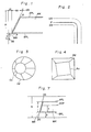
- Fig. 1 is a view for explaining such taper cutting, in which a wire electrode WR is stretched between an upper guide UG and a lower gide DG at a predetermined angle of inclination with respect to a workpiece WK.
- the lower plane BPL of the workpiece WK as the programmed plane (the upper plane APL of the workpiece WK may also serve as the programmed plane)
- H the distance between the upper guide UG and lower guide D G
- h the distance from the lower guide DG to the lower plane BPL of the workpiece WK
- the offset d 1 of the lower guide DG and the offset d 2 of the upper guide UG with respect to the lower plane BPL of the workpiece may be expressed as follows: Note that d is the cut width.
- a programmed path in the upper or lower plane of the workpiece, feedrate on the programmed path, taper angle a and distances H, h, etc., are commanded as set forth above and cutting is carried out in the manner commanded.
- taper cutting can be carried out through simple control if the taper angle is constant.
- an object of the present invention is to provide a wire electric discharge machining method through which taper cutting can be simply performed even for a contour having a continuously changing taper angle, and even if the contours cut on the upper and lower planes of a workpiece differ.
- Another object of the present invention is to provide a wire electric discharge machining method - capable of forming NC data from path data specifying contours to be cut on the upper and lower planes of a workpiece.
- a further object of the present invention is to provide a wire electric discharge machining method wherein NC data need not be recreated even when there is a change in a workpiece mounting position, a guide position or an amount of wire diameter compensation.
- the present invention provides a wire electric discharge machining method for cutting a workpiece by moving a wire electrode relative to the workpiece and producing an electric discharge across the wire electrode and workpiece.
- the method includes preparing and entering path data specifying contours to be cut on upper and lower planes of a workpiece, separately preparing and entering such auxiliary data as an amount of wire diameter compensation, workpiece mounting position and guide positions necessary for moving the wire electrode relative to the workpiece, obtaining relative path data between the workpiece and an upper guide tensioning the wire electrode as well as relative path data between the workpiece and a lower guide tensioning the wire electrode by using the path data and the auxiliary data, and taper cutting contours commanded on the upper and lower planes of the workpiece by moving the upper and lower guides relative to the workpiece using bot : . path data.
- Figs. 1 and 2 are views for describing a conventional taper cutting method
- Figs. 3 and 4 are cut contour views for describing the drawbacks of the prior art
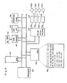
- Fig. 5 is a block diagram for practicing a first wire electric discharge machining method according to the present invention
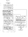
- Fig. 6 is a flowchart of processing associated with the method
- Fig. 7 is a view for describing auxiliary data
- Figs. 8 through 12 are views for describing programming methods
- Fig. 13 is a view for describing offset processing
- Fig. 14 is a view for describing an inconvenience of the first wire electric discharge machining method
- Fig. 15 is a flowchart of processing associated with a second wire electric discharge machining method
- Fig. 16 is a view for describing an inconvenience of a third wire electric discharge machining method.
- Fig. 5 is a block diagram for practicing a first wire electric discharge machining method according to the present invention
- Fig. 6 is a flowchart of processing associated with the method
- Fig. 7 is a view for describing auxiliary data
- Figs. 8 through 12 are views for describing programming methods.
- NC data specifying the cut contours On the upper and lower planes of a workpiece are recorded beforehand on an NC tape 101.
- the NC data are created in accordance with rules set forth below. It should be noted that there are cases where the upper and lower planes of the workpiece are referred to as programmed planes and programmed auxiliary planes. Either the programmed plane or programmed auxiliary plane may the upper plane of the workpiece.
- NC data are for setting a coordinate system.
- the coordinate system setting is commanded by the G-function instruction "G92”
- the present position of the wire electrode WR on the programmed plane BPL (Fig. 8) is commanded by the numerical values x, y that follow the respective word addresses "X”, "Y”, and the distance between the programmed plane and the programmed auxiliary plane (namely the thickness of the workpiece) is commanded by the numerical value i following the word address "I”.
- i shall be positive if the programmed auxiliary plane is the upper plane as seen from the programmed plane, and negative if the programmed auxiliary plane is the lower plane.
- the position of the wire electrode on the programmed auxiliary plane is calculated automatically from the inclination of the wire electrode and therefore need not be commanded.
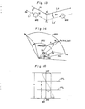
- the wire electrode paths (cut contours) on the programmed plane BPL and programmed auxiliary plane APL are LN, LN', respectively, as shown in Fig. 9, the paths are specified by the linear motion G-function instruction "GOl” and the numerical values x, y, u, v that follow the word addresses "X", "Y", “U”, “V”, respectively.
- the values of x, y specifying the path LN on the programmed plane BPL are incremental quantities along the respective axes from a starting point P s to an end point P e of the path on the programmed plane.
- the values of u, v specifying the path LN' on the programmed auxiliary plane APL are deviation quantities along the respective axes between the path end point P e on the programmed plane BPL and a path end point P e ' on the programmed auxiliary plane (a deviation quantity in the direction of workpiece thickness is not considered).
- the wire electrode paths on the programmed plane and programmed auxiliary plane are circular arcs ARB, ARA, respectively, as shown in Fig. 10, the paths are specified by the arcuate motion G-function instruction "G02" (clockwise) or "G03” (counter-clockwise) and the numerical values that follow the word addresses "X", "Y", “I”, “J”, “U”, “V”, “K”, “L” respectively.
- the numerical values x, y following the word addresses "X", "Y” indicate incremental values along the respective axes from an.
- the numerical values u, v following the word addresses "U”, “V”, respectively, are deviation quantities along the respective axes between the circular arc end point P e on the programmed plane and a circular arc end point P e ' on the programmed auxiliary plane (a deviation quantity in the direction of workpiece thickness is not considered).
- the numerical values k, 1 following the word addresses "K", "L", respectively, are deviation quantities along the respective axes between the center P c of the circular arc on the programmed plane and the center P c ' of the circular arc on the programmed auxiliary plane.
- NC data shown in Figs. 11 and 12, in which WR denotes the wire electrode, and WK the workpiece.
- (A) shows a plan view and ( B ) a front view.
- auxiliary data is entered from a manual data input unit (abbreviated to "MDI unit) 102.
- the auxiliary data include, with reference to Fig. 7, vertical distance H from the lower guide DG to the upper guide UG, vertical distance h from the lower guide DG to the programmed plane (lower plane of workpiece) BPL, vertical distance t from the programmed plane to a velocity control plane VCP, wire diameter compensation quantity D, travelling velocity f on the velocity control plane, and the like, these being entered from the MDI unit. Machining velocity f and distance t may entered from the NC tape 1. Also, rather than commanding the travelling velocity directly, so-called servofeed may be adopted wherein travelling velocity is commanded by a machining power supply.
- the data entered from the MDI unit 102 are read and stored in a RAM 105 by a processor 104 under the control of a control program stored in a ROM 103.
- the processor 104 under the control of the control program, obtains an offset path on the programmed plane and on the programmed auxiliary plane by using the wire diameter compensation quantity D, which has been stored in the RAM 105, the data indicative of wire diameter compensation direction, which are contained in the NC data, and the path data in the current and next blocks.
- Fig. 13 is a view for describing offset path calculation. Assuming that a programmed path comprises two straight lines L 1 , L 2 , as shown in Fig. 13, wire diameter compensation is carried out through a sequence of prereading a move command in a current block b l and a move command in the next block b 2 , obtaining a straight line L 1 ' by offsetting the straight line L 1 in the current block b l by the wire diameter compensation quantity D as well as a straight line L 2 ' by offsetting the straight line L 2 of the next block b 2 by the wire diameter compensation quantity, and computing the coordinate values of the point S 1 at which the straight lines L l ' and L 2 ' intersect. When this has been accomplished, the path connecting the end point S 0 of the preceding block and the point S 1 will be the offset path.
- the processor calculates incremental quantities (X w1 , Y w1 ), (X w2' Y w2 ) along the respective axes on the programmed plane and programmed auxiliary plane if the current block calls for linear motion, or calculates incremental quantities from circular arc end points to circular arc starting points and to centers of the circular arcs on the programmed plane and programmed auxiliary plane if the current block calls for arcuate motion. If the current block calls for linear cutting and an incremental quantity GOlXxYyUuVv; is commanded, then the processor 104 obtains incremental quantities along the respective axes in accordance with the equations and stores these quantities in the RAM 105. [Since offset processing is being executed, the incremental quantities along the respective axes naturally will be slightly different from (3). To simplify the discussion, however, the description is based on the assumption that the axial incremental quantities are expressed by the equations (3)].
- the processor 104 calculates and stores in the RAM 105, incremental quantities X f , Y f on the velocity control plane, incremental quantities X d , Y d for the lower guide, and incremental quantities X u , Y u for the upper guide in accordance with the following equations:
- the processor 104 calculates, and stores in the RAM 105, the travelling distances Ld, L u , L f on the lower guide plane, upper guide plane and velocity control plane, respectively:
- the method adopted in the following steps (g) through (i) includes finding travel quantities ⁇ x d ', ⁇ y d ', ⁇ x u ', ⁇ y u ' for moving the lower and upper guides along the respective axes in a time period ⁇ T preset as a parameter, applying ⁇ x d ', ⁇ y d ', ⁇ x u ', ⁇ y u ' to a pulse interpolator every ⁇ T seconds, and causing the pulse interpolator to distribute these quantities smoothly in the form of pulses along the. respective axes independently to move the upper and lower guides relative to the workpiece.
- the processor 104 After calculating the travelling distances in accordance with Egs. (5a) through (5c), the processor 104 obtains a shift quantity s necessary for shifting the most significant bit of the largest value among L d , L u , L f to the most significant digit (MSD) of an m-bit register, and stores the shift quantity in the RAM 105.
- m is the number of bits of a general purpose register in the processor 104.
- the incremental quantities X d , Y d ; X u , Y u for the lower and upper guides are each multiplied s times (s-bit shift), these are then stored in the m-bit register, and a two-axis simultaneous DDA interpolation calculation is performed at the respective adding rates fn 1 , fn 2 (times/second).
- the respective travel quantities ⁇ x d , ⁇ y d for moving the lower guide in one second of time take on the form and the respective travel quantities ⁇ x u , ⁇ y u for moving the upper guide in one second of time take on the form
- the velocities f d , f u of the lower and upper guides may be written as follows:
- Interpolated pulses P dx' P dy' P ux' P uy obtained as a result of the pulse interpolation calculation are applied to respective servo circuits 109 through 112, whereby the upper and lower guides are moved relative to the workpiece.
- the calculations of steps (h), (i) are performed and the following operations are executed to update present positions x ad ' y ad ⁇ x au' y au stored in the RAM 105 :
- the processor also performs the operations to update quantities x rd' y rd ' x ru' y ru indicative of distances remaining to be travelled, which are stored in the RAM 105.
- the inital values of the remaining travel quantities x rd' y rd' x ru' y ru are the incremental quantities X d , Y d , X u' Y u , which were calculated in accordance with Eqs. (4c) through (4f). Further, the processor 104 determines every d T seconds whether the following hold:
- K f in Eq. (7) is expressed by Eg. (8).
- K f cannot be expressed by Eq. (8). Instead, we have The reasons are as follows.
- X d , Y d represent incremental quantities along respective axes from the center of the circular arc for the lower guide to the starting point of the arc
- X , Y represent incremental quantities along respective axes from the center of the circular arc for the upper guide to the starting point of the arc.
- ARD repersents a circular arc trajectory on the plane of the lower guide
- ARU represents a circular arc trajectory on the plane of the upper guide.
- Fig. 15 shows a processing method for a second wire electric discharge machining method according to the present invention.
- the actually cut contours are accurate circular arcs on the upper and lower planes of the workpiece, unlike the contours cut according to the first method.
- the hardware for practicing the second method has the same arrangement as that shown in Fig. 5.
- step (f) onward of the second wire electric discharge machining method can also be performed in the following manner:
- the wire electrode advances while being moved back and forth in the following manner: solid line position ⁇ dotted line position ⁇ one-dot chain line position.
- the wire electrode advances while moving back and forth because the upper and lower guides are controlled each time one pulse is generated for the upper and lower planes of the workpiece. This problem does not occur with the second wire electric discharge machining method.
- the arrangement is such that the contours to oe cut in the upper and lower planes of a workpiece are given as NC data, auxiliary data necessary for moving a wire electrode relative to the workpiece are entered, and paths on the upper and lower planes of the workpiece are converted into paths of upper and lower guides relative to the workpiece. Accordingly, taper cutting can be performed in simple fashion even if a taper varies in a continuous manner and the contours cut in the upper and lower planes of the workpiece differ.
- an NC tape is formed from path data specifying the contours to be cut on the upper and lower planes of the workpiece, and it is arranged so that such corrective data as workpiece mounting position, guide positions and amount of wire diameter compensation can be entered separately from an MDI unit. Accordingly, NC data need not be recreated even if the auxiliary data change.
Landscapes
- Chemical & Material Sciences (AREA)
- Chemical Kinetics & Catalysis (AREA)
- Electrochemistry (AREA)
- Engineering & Computer Science (AREA)
- Mechanical Engineering (AREA)
- Electrical Discharge Machining, Electrochemical Machining, And Combined Machining (AREA)
Abstract
Applications Claiming Priority (2)
| Application Number | Priority Date | Filing Date | Title |
|---|---|---|---|
| JP163713/83 | 1983-09-06 | ||
| JP58163713A JPS6056824A (ja) | 1983-09-06 | 1983-09-06 | ワイヤ放電加工方法 |
Publications (3)
| Publication Number | Publication Date |
|---|---|
| EP0155323A1 true EP0155323A1 (fr) | 1985-09-25 |
| EP0155323A4 EP0155323A4 (fr) | 1987-06-29 |
| EP0155323B1 EP0155323B1 (fr) | 1989-06-07 |
Family
ID=15779220
Family Applications (1)
| Application Number | Title | Priority Date | Filing Date |
|---|---|---|---|
| EP84903359A Expired EP0155323B1 (fr) | 1983-09-06 | 1984-09-06 | Procede d'usinage a decharge electrique du type a fil |
Country Status (5)
| Country | Link |
|---|---|
| US (1) | US4703146A (fr) |
| EP (1) | EP0155323B1 (fr) |
| JP (1) | JPS6056824A (fr) |
| DE (1) | DE3478583D1 (fr) |
| WO (1) | WO1985001001A1 (fr) |
Cited By (1)
| Publication number | Priority date | Publication date | Assignee | Title |
|---|---|---|---|---|
| EP0406918A3 (en) * | 1985-09-27 | 1991-05-02 | Raycon Corporation | Method and apparatus for electric discharge machining |
Families Citing this family (26)
| Publication number | Priority date | Publication date | Assignee | Title |
|---|---|---|---|---|
| JPS62120919A (ja) * | 1985-11-20 | 1987-06-02 | Fanuc Ltd | ワイヤカツト放電加工方法 |
| JP2520609B2 (ja) * | 1986-09-06 | 1996-07-31 | ファナック 株式会社 | ワイヤ放電加工方法 |
| JPS63123630A (ja) * | 1986-11-13 | 1988-05-27 | Mitsubishi Electric Corp | ワイヤ放電加工機 |
| JPS642106A (en) * | 1987-06-24 | 1989-01-06 | Fanuc Ltd | System for controlling involute interpolating speed |
| DE3810662A1 (de) * | 1988-03-29 | 1989-10-19 | Agie Ag Ind Elektronik | Verfahren und vorrichtung zur numerischen bahnsteuerung fuer elektroerodiermaschinen |
| JPH0271928A (ja) * | 1988-09-01 | 1990-03-12 | Mitsubishi Electric Corp | ワイヤ放電加工におけるワイヤ径補正量の算出方法 |
| JPH02100109A (ja) * | 1988-10-07 | 1990-04-12 | Mitsubishi Electric Corp | 数値制御装置のcrt表示方法 |
| JPH02116422A (ja) * | 1988-10-27 | 1990-05-01 | Mitsubishi Electric Corp | ワイヤカット放電加工方法 |
| US5051912A (en) * | 1989-02-07 | 1991-09-24 | Hurco Acquisition Corporation | Vectoring/orbiting control unit for electrical discharge machining |
| JPH02279220A (ja) * | 1989-04-19 | 1990-11-15 | Mitsubishi Electric Corp | ワイヤ放電加工装置 |
| JP2691613B2 (ja) * | 1989-05-08 | 1997-12-17 | 菱電工機エンジニアリング株式会社 | Cad/cam装置 |
| JPH02311220A (ja) * | 1989-05-26 | 1990-12-26 | Hitachi Seiko Ltd | ワイヤ放電加工方法 |
| JPH0722875B2 (ja) * | 1989-05-30 | 1995-03-15 | 三菱電機株式会社 | プログラミング装置のテーパ角設定表示方法 |
| US5095734A (en) * | 1990-12-14 | 1992-03-17 | William L. Bonnell Company, Inc. | Extrusion die and method for extruding aluminum |
| JPH08243846A (ja) * | 1995-03-06 | 1996-09-24 | Mitsubishi Electric Corp | ワイヤ放電加工装置及び方法 |
| JP2004142027A (ja) * | 2002-10-24 | 2004-05-20 | Fanuc Ltd | ワイヤ放電加工機 |
| US6836741B2 (en) * | 2003-01-30 | 2004-12-28 | Industrial Technology Reseach Institute | Vertical calibration method for a wire cut electric discharge machine |
| DE10322340B4 (de) * | 2003-05-17 | 2006-09-14 | Mtu Aero Engines Gmbh | Verfahren und Vorrichtung zum Fräsen von Freiformflächen |
| JP4472558B2 (ja) * | 2005-03-03 | 2010-06-02 | 株式会社ソディック | ワイヤカット放電加工方法 |
| JP4072548B2 (ja) * | 2005-09-26 | 2008-04-09 | ファナック株式会社 | ワイヤ放電加工機 |
| JP5088975B2 (ja) * | 2010-10-19 | 2012-12-05 | 株式会社ソディック | ワイヤ放電加工装置 |
| JP4938137B1 (ja) * | 2011-03-03 | 2012-05-23 | ファナック株式会社 | 被加工物の上面検出機能を有するワイヤカット放電加工機 |
| JP5369205B2 (ja) * | 2012-02-27 | 2013-12-18 | ファナック株式会社 | 切込み加工時、逃げ加工時の加工傷を低減するワイヤ放電加工機およびワイヤ放電加工方法 |
| US8977382B2 (en) | 2012-05-11 | 2015-03-10 | D.P. Technology Corp. | Automatic method for milling complex channel-shaped cavities |
| US9927801B2 (en) | 2012-05-11 | 2018-03-27 | D.P. Technology Corp. | Automatic method for milling complex channel-shaped cavities via coupling flank-milling positions |
| JP6490118B2 (ja) * | 2017-01-26 | 2019-03-27 | ファナック株式会社 | 数値制御装置 |
Family Cites Families (18)
| Publication number | Priority date | Publication date | Assignee | Title |
|---|---|---|---|---|
| JPS52112194A (en) * | 1976-03-18 | 1977-09-20 | Houden Seimitsu Kakou Kenkiyuu | Control system of wire electrode discharge machining device |
| FR2371267A1 (fr) * | 1976-11-19 | 1978-06-16 | Charmilles Sa Ateliers | Procede et dispositif pour l'usinage par etincelage erosif |
| JPS53132895A (en) * | 1977-04-25 | 1978-11-20 | Inoue Japax Res Inc | Method of tapering in wire-cutting discharge processings |
| JPS5499294A (en) * | 1978-01-23 | 1979-08-04 | Mitsubishi Electric Corp | Tape maker for wire-cut discharge cutting machines |
| GB2041574B (en) * | 1978-12-08 | 1983-03-09 | Inoue Japax Res | Microprocessor - controlled edm method and apparatus |
| JPS55120934A (en) * | 1979-03-13 | 1980-09-17 | Mitsubishi Electric Corp | Wire cut-type electric current machining |
| JPS5639832A (en) * | 1979-09-06 | 1981-04-15 | Fanuc Ltd | Wire cut electric discharge machining method |
| JPS594252B2 (ja) * | 1979-09-08 | 1984-01-28 | フアナツク株式会社 | テ−パ加工方法 |
| JPS5766823A (en) * | 1980-10-08 | 1982-04-23 | Fanuc Ltd | Wire cutting discharge processing system |
| JPS57166606A (en) * | 1981-04-04 | 1982-10-14 | Fanuc Ltd | Numerical control working method |
| JPS5851020A (ja) * | 1981-09-22 | 1983-03-25 | Fanuc Ltd | ワイヤカツト放電加工方式 |
| JPS58109224A (ja) * | 1981-12-17 | 1983-06-29 | Fanuc Ltd | ワイヤカツト放電加工方式 |
| JPS5981023A (ja) * | 1982-10-27 | 1984-05-10 | Fanuc Ltd | ワイヤカツトテ−パ加工方法 |
| JPH106994A (ja) * | 1996-06-25 | 1998-01-13 | Nippon Signal Co Ltd:The | 踏切制御装置 |
| JPH109224A (ja) * | 1996-06-25 | 1998-01-13 | Sony Corp | フレキシブルプリント配線板の固定用クリップ及びこれを用いたフレキシブルプリント配線板の固定補強方法 |
| US5841835A (en) * | 1997-03-31 | 1998-11-24 | General Electric Company | Apparatus and method for automatic monitoring and assessment of image quality in x-ray systems |
| JP3031297B2 (ja) * | 1997-06-12 | 2000-04-10 | ダイキン工業株式会社 | スクロール圧縮機 |
| JP3504826B2 (ja) * | 1997-06-18 | 2004-03-08 | 矢崎総業株式会社 | 防水保護カバー |
-
1983
- 1983-09-06 JP JP58163713A patent/JPS6056824A/ja active Pending
-
1984
- 1984-09-06 WO PCT/JP1984/000426 patent/WO1985001001A1/fr not_active Ceased
- 1984-09-06 DE DE8484903359T patent/DE3478583D1/de not_active Expired
- 1984-09-06 US US06/732,010 patent/US4703146A/en not_active Expired - Lifetime
- 1984-09-06 EP EP84903359A patent/EP0155323B1/fr not_active Expired
Cited By (1)
| Publication number | Priority date | Publication date | Assignee | Title |
|---|---|---|---|---|
| EP0406918A3 (en) * | 1985-09-27 | 1991-05-02 | Raycon Corporation | Method and apparatus for electric discharge machining |
Also Published As
| Publication number | Publication date |
|---|---|
| DE3478583D1 (en) | 1989-07-13 |
| EP0155323A4 (fr) | 1987-06-29 |
| JPS6056824A (ja) | 1985-04-02 |
| WO1985001001A1 (fr) | 1985-03-14 |
| US4703146A (en) | 1987-10-27 |
| EP0155323B1 (fr) | 1989-06-07 |
Similar Documents
| Publication | Publication Date | Title |
|---|---|---|
| EP0155323A1 (fr) | Procede d'usinage a decharge electrique du type a fil | |
| KR880002554B1 (ko) | 수치 제어 가공방법 | |
| US4843203A (en) | Taper cutting control method and control system in wire-cut electric discharge machine | |
| US3731044A (en) | Electro-eroding machine with a circuit for the control of at least one advancing device for a wire electrode and/or for a workpiece | |
| US4533286A (en) | Tool compensation method | |
| US4649252A (en) | Wire-cut electric discharge machining method | |
| EP0214295B1 (fr) | Appareil de commande de l'operation de tournage conique d'une machine d'usinage a decharge electrique a fil de coupe | |
| US4355223A (en) | Electroerosion method and system for taper cutting with travelling wire electrode | |
| US4739489A (en) | Area cutting method | |
| US4700314A (en) | Taper cutting method | |
| EP0068029A1 (fr) | Procede de commande d'usinage par electro-erosion a fil | |
| EP0062073A1 (fr) | Procede de commande d'usinage a electroerosion par fil | |
| US5021622A (en) | Wire cut electrical discharge machine | |
| US4983807A (en) | Method and apparatus for plasma cutting a workpiece | |
| US5030819A (en) | Method and device for numerical control for electroerosion machine | |
| US6972389B2 (en) | Method and apparatus for preparing program for die machining | |
| JP2914101B2 (ja) | ワイヤ放電加工方法及びその装置 | |
| JPS594252B2 (ja) | テ−パ加工方法 | |
| JP3288799B2 (ja) | ワイヤ放電加工機 | |
| JPS5828424A (ja) | 放電加工機のテ−パ加工用ガイド及びテ−パ加工装置 | |
| EP0124611B1 (fr) | Procede d'usinage par fil de coupe de pieces coniques | |
| JPH04764B2 (fr) | ||
| JPS6351811B2 (fr) | ||
| JPS59161236A (ja) | ワイヤカツト放電加工機におけるコ−ナ加工方法 | |
| JPH03117519A (ja) | ワイヤ放電加工方法 |
Legal Events
| Date | Code | Title | Description |
|---|---|---|---|
| PUAI | Public reference made under article 153(3) epc to a published international application that has entered the european phase |
Free format text: ORIGINAL CODE: 0009012 |
|
| 17P | Request for examination filed |
Effective date: 19850515 |
|
| AK | Designated contracting states |
Designated state(s): CH DE GB LI |
|
| A4 | Supplementary search report drawn up and despatched |
Effective date: 19870629 |
|
| 17Q | First examination report despatched |
Effective date: 19880510 |
|
| GRAA | (expected) grant |
Free format text: ORIGINAL CODE: 0009210 |
|
| AK | Designated contracting states |
Kind code of ref document: B1 Designated state(s): CH DE GB LI |
|
| REF | Corresponds to: |
Ref document number: 3478583 Country of ref document: DE Date of ref document: 19890713 |
|
| PLBE | No opposition filed within time limit |
Free format text: ORIGINAL CODE: 0009261 |
|
| STAA | Information on the status of an ep patent application or granted ep patent |
Free format text: STATUS: NO OPPOSITION FILED WITHIN TIME LIMIT |
|
| 26N | No opposition filed | ||
| PGFP | Annual fee paid to national office [announced via postgrant information from national office to epo] |
Ref country code: DE Payment date: 19980914 Year of fee payment: 15 |
|
| PGFP | Annual fee paid to national office [announced via postgrant information from national office to epo] |
Ref country code: GB Payment date: 19981001 Year of fee payment: 15 |
|
| PG25 | Lapsed in a contracting state [announced via postgrant information from national office to epo] |
Ref country code: GB Free format text: LAPSE BECAUSE OF NON-PAYMENT OF DUE FEES Effective date: 19990906 |
|
| GBPC | Gb: european patent ceased through non-payment of renewal fee |
Effective date: 19990906 |
|
| PG25 | Lapsed in a contracting state [announced via postgrant information from national office to epo] |
Ref country code: DE Free format text: LAPSE BECAUSE OF NON-PAYMENT OF DUE FEES Effective date: 20000701 |
|
| PGFP | Annual fee paid to national office [announced via postgrant information from national office to epo] |
Ref country code: CH Payment date: 20030918 Year of fee payment: 20 |
|
| PG25 | Lapsed in a contracting state [announced via postgrant information from national office to epo] |
Ref country code: LI Free format text: LAPSE BECAUSE OF EXPIRATION OF PROTECTION Effective date: 20040905 Ref country code: CH Free format text: LAPSE BECAUSE OF EXPIRATION OF PROTECTION Effective date: 20040905 |
|
| REG | Reference to a national code |
Ref country code: CH Ref legal event code: PL |