EP0214385A2 - Brushless induction machine - Google Patents
Brushless induction machine Download PDFInfo
- Publication number
- EP0214385A2 EP0214385A2 EP86108668A EP86108668A EP0214385A2 EP 0214385 A2 EP0214385 A2 EP 0214385A2 EP 86108668 A EP86108668 A EP 86108668A EP 86108668 A EP86108668 A EP 86108668A EP 0214385 A2 EP0214385 A2 EP 0214385A2
- Authority
- EP
- European Patent Office
- Prior art keywords
- induction machine
- rotor
- machine according
- winding
- taps
- Prior art date
- Legal status (The legal status is an assumption and is not a legal conclusion. Google has not performed a legal analysis and makes no representation as to the accuracy of the status listed.)
- Withdrawn
Links
Images
Classifications
-
- H—ELECTRICITY
- H02—GENERATION; CONVERSION OR DISTRIBUTION OF ELECTRIC POWER
- H02K—DYNAMO-ELECTRIC MACHINES
- H02K39/00—Generators specially adapted for producing a desired non-sinusoidal waveform
-
- G—PHYSICS
- G01—MEASURING; TESTING
- G01P—MEASURING LINEAR OR ANGULAR SPEED, ACCELERATION, DECELERATION, OR SHOCK; INDICATING PRESENCE, ABSENCE, OR DIRECTION, OF MOVEMENT
- G01P3/00—Measuring linear or angular speed; Measuring differences of linear or angular speeds
- G01P3/42—Devices characterised by the use of electric or magnetic means
- G01P3/44—Devices characterised by the use of electric or magnetic means for measuring angular speed
- G01P3/46—Devices characterised by the use of electric or magnetic means for measuring angular speed by measuring amplitude of generated current or voltage
- G01P3/465—Devices characterised by the use of electric or magnetic means for measuring angular speed by measuring amplitude of generated current or voltage by using dynamo-electro tachometers or electric generator
-
- H—ELECTRICITY
- H02—GENERATION; CONVERSION OR DISTRIBUTION OF ELECTRIC POWER
- H02K—DYNAMO-ELECTRIC MACHINES
- H02K21/00—Synchronous motors having permanent magnets; Synchronous generators having permanent magnets
- H02K21/12—Synchronous motors having permanent magnets; Synchronous generators having permanent magnets with stationary armatures and rotating magnets
- H02K21/14—Synchronous motors having permanent magnets; Synchronous generators having permanent magnets with stationary armatures and rotating magnets with magnets rotating within the armatures
Definitions
- the invention relates to a brushless n-phase and n-pole induction machine, for example a DC tachometer dynamo, for generating trapezoidal voltages, with a rotor having magnets and with a stator carrying at least one winding.
- a brushless n-phase and n-pole induction machine for example a DC tachometer dynamo, for generating trapezoidal voltages, with a rotor having magnets and with a stator carrying at least one winding.
- Induction machines for generating trapezoidal output voltages are used in a wide variety of applications in measurement, control and drive technology, where it is necessary to have a DC signal proportional to the speed.
- High demands are made, for example, on the control of drives that usually run at an exact speed, such as centrifuges, machine tools and elevators, and in which the speed must be variable over a wide range.
- a brushless induction machine of the type described at the outset is known from German utility model G 83 24 702, with multiphase, phase-shiftable windings located in an air gap between the rotor and stator.
- Each phase of the winding has four coils, each of which is divided into two sub-coils lying one above the other in the radial direction.
- the coils are arranged in a bobbin in such a way that the two partial coils of one phase lie between the two coils of another phase that follow in the circumferential direction at the intersections and that the two partial coil pairs overlap there.
- this known induction machine has the disadvantage that the windings have to be inserted very precisely onto the plastic bobbin in the air gap with a relatively large production outlay.
- the invention is therefore based on the object of specifying an induction machine of the type mentioned at the outset, which is provided with simply shaped pole pieces and thereby has a homogeneous magnetic field.
- stator has at least one short-circuited winding which is uniformly distributed over an annular core which is concentric with the rotor and which is provided with at least two taps which are offset in the circumferential direction to tap the trapezoidal voltages.
- the principle of the invention is that the homogeneity required to generate the constant part of the trapezoidal voltage is not placed in the magnetic field, but in the winding.
- the same number of turns per time unit occur in the magnetic field when the rotor rotates, as turns emerge from the magnetic field on its rear side. Since the windings are distributed uniformly over the toroidal core according to the invention, the same number of windings are always newly cut by the magnetic field per unit of time.
- the invention has the advantage that precision tachometer dynamos can be produced, which are characterized by a ripple of less than 1.5%. Furthermore, asymmetries of the magnetic field in the air gap which may arise due to manufacturing tolerances and which can lead to slight differences in the voltages induced by the rotor magnets can be compensated for by the short-circuit currents caused in the winding.
- the taps are preferably mechanically arranged in pairs at an offset of 180 ° each. In this way, two mutually inverted trapezoidal voltages can be tapped, each of which extends electrically over 180 °.
- n ⁇ 2 taps are present in n poles, which belong together in pairs are offset.
- the frequency of the trapezoidal voltages on the output side is correspondingly increased.
- n 4 poles are present for a winding.
- An advantageous further development of the invention consists in the fact that the pole coverage angle of the roto is selected such that the trapezoidal voltages induced one after the other overlap in their constant proportion.
- stator is arranged concentrically around the rotor and consists of an annular sheet stack.
- stator is arranged on the side of the rotor and has an annular core made of a coiled sheet metal strip.
- the stator 1 is shown schematically as a ring core which is provided with a winding 2 uniformly from winding to winding.
- this winding 2 has 3 taps 6, 7, 8, 9 in a 2-pole rotor, which are each mechanically staggered by 90 °.
- the taps 6,7,8,9 are shown schematically as loops. Not removed from the figure bar that the winding 2 is endless, that is, that the result in terms of winding technology is connected to the end of the winding 2.
- the rotor 3 carries two magnets 4, 5, the flow of which penetrates the air gap between the magnets 4, 5 and the stator 1. There it divides into two partial flows, which penetrate the stator in both halves.
- a pole sequence north-south-north-south is selected as an example. This results in a first partial flow that extends from the south pole S shown on the right over the upper part of the toroid to the left north pole N and, on the other hand, a second partial flow that extends from the right south pole S through the lower part of the stator to the north pole shown at the top left N continues.
- the angle of rotation of the rotor is denoted by ⁇ .
- induction machine The function of the induction machine is described below with reference to FIGS. 1 and 2 when it is used as an example as a tachometer dynamo.
- the windings of the winding 2 are cut by a magnetic field.
- One turn comprises a magnetic flux ⁇ , which increases steadily with time, ie the angle of rotation of the rotor 3.
- the induced voltage is then according to the equation constant.
- the magnets 4, 5 rotate, the same number of turns of the winding 2 enter the magnetic field as the turns on the back emerge from the magnetic field. Since, according to the invention, the windings are distributed uniformly over the ring core of the stator, the same number of windings are always cut anew in the magnetic field per unit of time first induced the voltage u68.
- the voltage u79 is induced out of phase and can be tapped at the taps 7, 9.
- the induced voltage drops to zero in order to reverse its polarity.
- the angle of rotation is smaller than half the opening angle of the magnetic pole of the rotor when approaching one of the taps, the voltage drops steadily to zero.
- the tap is removed, the voltage rises accordingly until the angle of rotation ⁇ is greater than half the opening angle of the magnetic poles.
- the angle of rotation ⁇ is greater than the opening angle has a constant course of the voltage induced in this way.
- the coil can be short-circuited in itself.
- the trapezoidal voltages tapped between the taps belonging together in pairs are connected to a DC voltage via electronic switches, which are not shown in the figures. It can be seen from FIG. 2 that the voltage u capital is first switched on in the example shown. Then the voltage u79 is switched electronically. This is followed by the connection of the voltage u86, which is inverted to the voltage u68, in order to then use the inverted voltage u97.
- n-pole versions can also be implemented without difficulty.
- the induction machine according to the invention can also be operated as a motor which rotates uniformly with constant torque when trapezoidal voltages - corresponding to FIG. 2 - are applied to the taps 6, 7, 8, 9.
Landscapes
- Engineering & Computer Science (AREA)
- Power Engineering (AREA)
- Physics & Mathematics (AREA)
- General Physics & Mathematics (AREA)
- Permanent Magnet Type Synchronous Machine (AREA)
- Iron Core Of Rotating Electric Machines (AREA)
- Synchronous Machinery (AREA)
Abstract
Description
Die Erfindung betrifft eine bürstenlose n-phasige und n-polige Induktionsmaschine, beispielsweise einen Gleichspannungs-Tachometerdynamo, zum Erzeugen von Trapezspannungen, mit einem Magnete aufweisenden Rotor und mit einem mindestens eine Wicklung tragenden Stator.The invention relates to a brushless n-phase and n-pole induction machine, for example a DC tachometer dynamo, for generating trapezoidal voltages, with a rotor having magnets and with a stator carrying at least one winding.
Induktionsmaschinen zur Erzeugung von trapezförmigen Ausgangspannungen finden vielfältige Anwendungen in der Meß-, Regel- und Antriebstechnik, wo es erforderlich ist, ein drehzahlproportionales Gleichspannungssignal zur Verfügung zu haben. Hohe Anforderungen werden dabei beispielsweise an die Regelung von Antrieben gestellt, die gewöhnlich mit genauer Drehzahl laufen, wie beispielsweise Zentrifugen, Werkzeugmaschinen und Aufzüge, und bei welchen die Drehzahl in weiten Bereichen veränderbar sein muß.Induction machines for generating trapezoidal output voltages are used in a wide variety of applications in measurement, control and drive technology, where it is necessary to have a DC signal proportional to the speed. High demands are made, for example, on the control of drives that usually run at an exact speed, such as centrifuges, machine tools and elevators, and in which the speed must be variable over a wide range.
Zur Erzeugung einer Gleichspannung, deren Höhe der Drehzahl und deren Polarität der Drehrichtung entspricht, ist die Verwendung eines Gleichspannungs-Tachometerdynamos bekannt, bei welchem die in den Wicklungen induzierten Spannungen einen sinus-ähnlichen Verlauf aufweisen. Durch die dichte Aneinanderreihung von Ausschnitten dieser Spannung mit Hilfe eines Kollektors mit entsprechend hoher Lamellenzahl wird eine Gleichspannung mit gewisser Restwelligkeit erzeugt. Will man den Kollektor durch elektronische Schalter ersetzen und soll gleichzeitig deren Anzahl möglichst klein sein, so muß die induzierte Wechselspannung einen möglichst langen geraden Bereich aufweisen. Es wird daher angestrebt, trapezförmige Spannungen zeitlich nacheinander versetzt zu induzieren. Diese können durch eine entsprechend gesteuerte, elektronische Kommutierungsvorrichtung oder durch eine Gleichrichteranordnung in der Weise nacheinander eingeschaltet und aneinander gereiht werden, daß eine einer Gleichspannung entsprechende Ausgangsspannung abgreifbar ist. Die Gleichrichtung, d.h. das Herausgreifen des jeweils waagrechten Stückes der Trapezspannung durch zeitlich nacheinander angesteurerte elektronische Schalter ist an sich bekannt. Hierfür werden beispielsweise MOS-Schaltkreise eingesetzt.To generate a DC voltage, the magnitude of the speed and the polarity of the direction of rotation, the use of a DC tachometer dynamo is known in which the voltages induced in the windings have a sine-like curve. Due to the close arrangement of sections of this voltage with the aid of a collector with a correspondingly high number of fins, a DC voltage with a certain residual ripple is generated. If you want to replace the collector with electronic switches and at the same time their number is to be as small as possible, the induced AC voltage must have a long, straight area. The aim is therefore to induce trapezoidal voltages staggered in time. These can be switched on and connected to one another in succession by a correspondingly controlled electronic commutation device or by a rectifier arrangement be ranked that an output voltage corresponding to a DC voltage can be tapped. The rectification, ie the picking out of the horizontal piece of the trapezoidal voltage by successively controlled electronic switches is known per se. For example, MOS circuits are used for this.
Schwierigkeiten bereitet es jedoch, eine lückenlose Gleichspannung zu erzeugen, d.h.Trapezspannungen abzuleiten, deren Spannungsverlauf einen möglichst langen konstant verlaufenden Anteil aufweist, da Abweichungen von der Geraden sich nach der Gleichrichtung,d.h. nach der Aneinanderreihung der Trapezstücke, als Welligkeit bemerkbar machen. Wechselspannungsgeneratoren, deren Spannung mit Dioden gleichgerichtet wird, weisen beispielsweise eine Weilligkeit ihrer gleichgerichteten annähernd sinusförmigen Spannungen auf, die je nach Anzahl der eingesetzten Wicklungssysteme zwischen 7% und 13% liegt. Eine derartige hohe Welligkeit ist jedoch für Präzisions-Tachometerdynamos unter keinen Umständen tragbar.However, it is difficult to generate a continuous DC voltage, i.e. to derive trapezoidal voltages, the voltage profile of which has a constant component that is as long as possible, since deviations from the straight line vary according to the rectification, i.e. after lining up the trapezoidal pieces, make them noticeable as a ripple. AC voltage generators, the voltage of which is rectified with diodes, have, for example, a brightness of their rectified, approximately sinusoidal voltages, which is between 7% and 13% depending on the number of winding systems used. However, such a high ripple is under no circumstances acceptable for precision speedometer dynamos.
Aus dem deutschen Gebrauchsmuster G 83 24 702 ist eine bürstenlose Induktionsmaschine der eingangs beschriebenen Art bekannt, mit in einem Luftspalt zwischen Rotor und Stator liegenden mehrphasigen, phasenverschoben antsteuerbaren Wicklungen. Jede Phase der Wicklung weist vier Spulen auf, die jeweils in zwei in radialer Richtung übereinanderliegenden Teilspulen unterteilt sind. Die Spulen sind in einem Spulenkörper in der Weise angeordnet, daß an den Kreuzungsstellen jeweils die beiden Teilspulen einer Phase zwischen den in Umfangsrichtung nachfolgenden beiden Spulen einer anderen Phase liegen, und daß sich dort die beiden Teilspulenpaare überlappen. Diese bekannte Induktionsmaschine hat jedoch den Nachteil, daß die Wicklungen mit einem relativ großen Fertigungsaufwand sehr exakt auf den Kunststoff-Spulenkörper im Luftspalt eingelegt werden müssen. Ein weiterer Nachteil ist darin zu sehen, daß an den Rändern der verwendeten Polschuhe Inhomogenitäten des Magnetfeldes unvermeidlich sind, obwohl eine Abflachung der Polschuhe bzw. Magnete vorgesehen ist. Die Magnete haben in Magnetmitte eine geringere Dicke, wodurch sich eine Polabhebung in der Magnetmitte ergibt. Dabei ist sowohl eine sehnenartige Abhebung mit nicht kreisförmiger Magnetkrümmung als auch eine Abhebung durch Versatz der beiden Magnetmittelpunkte mit entsprechend vergrößerten Krümmungsradien möglich. Ebenso wie bei den Wicklungen sind also auch bei den Polschuhen zusätzliche Fertigungsschritte erforderlich, die die Herstellung einer derartigen Induktionsmaschine relative aufwendig erscheinen lassen.A brushless induction machine of the type described at the outset is known from German utility model G 83 24 702, with multiphase, phase-shiftable windings located in an air gap between the rotor and stator. Each phase of the winding has four coils, each of which is divided into two sub-coils lying one above the other in the radial direction. The coils are arranged in a bobbin in such a way that the two partial coils of one phase lie between the two coils of another phase that follow in the circumferential direction at the intersections and that the two partial coil pairs overlap there. However, this known induction machine has the disadvantage that the windings have to be inserted very precisely onto the plastic bobbin in the air gap with a relatively large production outlay. Another disadvantage is that inhomogeneities of the magnetic field are unavoidable at the edges of the pole pieces used, although a flattening of the pole pieces or magnets is provided. The magnets have a smaller thickness in the middle of the magnet, which results in a pole lift in the middle of the magnet. Both a tendon-like lift with a non-circular magnetic curvature and a lift by offset of the two magnet centers with correspondingly enlarged radii of curvature are possible. As with the windings, additional manufacturing steps are required for the pole shoes, which make the production of such an induction machine appear relatively complex.
Die Erfindung liegt daher die Aufgabe zugrunde, eine Induktionsmaschine der eingangs genannten Art anzugeben, welche mit einfach geformten Polschuhen versehen ist und dabei ein homogenes Magnetfeld aufweist.The invention is therefore based on the object of specifying an induction machine of the type mentioned at the outset, which is provided with simply shaped pole pieces and thereby has a homogeneous magnetic field.
Diese Aufgabe wird dadurch gelöst, daß der Stator mindestens eine in sich kurzgeschlossene, über einen zum Rotor konzentrischen Ringkern gleichmäßig verteilte Wicklung aufweist, die mit mindestens zwei, in Umfangsrichtung gegeneinander versetzten Anzapfungen zum Abgriff der Trapezspannungen versehen ist.This object is achieved in that the stator has at least one short-circuited winding which is uniformly distributed over an annular core which is concentric with the rotor and which is provided with at least two taps which are offset in the circumferential direction to tap the trapezoidal voltages.
Das Prinzip der Erfindung liegt darin, daß die für die Erzeugung des konstanten Teils der Trapezspannung erforderliche Homogenität nicht in das magnetische Feld, sondern in die Wicklung gelegt wird. Durch Aufteilung des Magnetflusses im Ringkern in zwei Teilflüsse, die den Ringkern in beiden Hälften durchsetzen, treten bei einer Drehung des Rotors pro Zeiteinheit die gleiche Anzahl von Windungen in das Magnetfeld ein, wie auf seiner Rückseite Windungen aus dem Magnetfeld heraustreten. Da die Windungen erfindungsgemäß gleichförmig über den Ringkern verteilt sind, werden also pro Zeiteinheit stets die gleiche Anzahl von Windungen neu vom Magnetfeld geschnitten.The principle of the invention is that the homogeneity required to generate the constant part of the trapezoidal voltage is not placed in the magnetic field, but in the winding. By dividing the magnetic flux in the ring core into two partial flows, which penetrate the ring core in both halves, the same number of turns per time unit occur in the magnetic field when the rotor rotates, as turns emerge from the magnetic field on its rear side. Since the windings are distributed uniformly over the toroidal core according to the invention, the same number of windings are always newly cut by the magnetic field per unit of time.
Die Erfindung hat den Vorteil, daß Präzisions-Tachometerdynamos hergestellt werden können, welche sich durch eine Welligkeit von weniger als 1,5% auszeichnen. Ferner können möglicherweise aufgrund von Fertigungstoleranzen entstehende Unsymmetrien des Magnetfeldes im Luftspalt, die zu geringen Unterschieden der von den Rotormagneten induzierten Spannungen führen können, durch die in der Wicklung hervorgerufenen Kurzschlußströme ausgeglichen werden.The invention has the advantage that precision tachometer dynamos can be produced, which are characterized by a ripple of less than 1.5%. Furthermore, asymmetries of the magnetic field in the air gap which may arise due to manufacturing tolerances and which can lead to slight differences in the voltages induced by the rotor magnets can be compensated for by the short-circuit currents caused in the winding.
Vorzugsweise sind die Anzapfungen paarweise unter einem Versatz von jeweils 180° mechanisch angeordnet. Auf diese Weise sind zwei zueinander invertierte Trapezspannungen abgreifbar, die sich jeweils über 180° elektrisch erstrecken.The taps are preferably mechanically arranged in pairs at an offset of 180 ° each. In this way, two mutually inverted trapezoidal voltages can be tapped, each of which extends electrically over 180 °.
In einer vorteilhaften Weiterbildung der Erfindung sind bei n Polen n·2 Anzapfungen vorhanden, die paarweise zusammengehörig um
Bei der elektronischen Gleichrichtung bzw. bei der Aneinanderreihung der Trapezspannungen hat es sich als vorteilhaft erwiesen, wenn m Wicklungen vorhanden sind ( m = 2,3..)und daß jede Wicklung mindestens ein Paar Anzapfungen aufweist.In the case of electronic rectification or when the trapezoidal voltages are strung together, it has proven to be advantageous if there are m windings (m = 2.3 ..) and that each winding has at least one pair of taps.
Besonders günstig ist es, wenn die Anzapfungen der Wicklungen untereinander um
In einer vorteilhaften Ausführungsform der Erfindung ist eine Wicklung vorhanden und weist der Rotor N=2 Pole auf.In an advantageous embodiment of the invention there is a winding and the rotor has N = 2 poles.
In einer weiteren vorteilhaften Ausführungsform sind bei einer Wicklung n=4 Pole vorhanden. Eine besonders vorteilhafte Weiterbildung der Erfindung weist m=2 Windungen und n=2 Pole auf.In a further advantageous embodiment, n = 4 poles are present for a winding. A particularly advantageous development of the invention has m = 2 turns and n = 2 poles.
Unter wicklungstechnischen Gesichtspunkten erweist es sich als vorteilhaft, wenn in einer Ausführungsform der Erfindung der Anfang und das Ende der Wicklung in einer der Anzapfungen kurzgeschlossen ist.In terms of winding technology, it proves to be advantageous if, in one embodiment of the invention, the start and the end of the winding are short-circuited in one of the taps.
Eine vorteilhafte Weiterbildung der Erfindung besteht darin, daß der Polbedeckungswinkel des Rotos so gewählt ist, daß sich jeweils hintereinander induzierte Trapezspannungen in ihrem konstanten Anteil überlappen.An advantageous further development of the invention consists in the fact that the pole coverage angle of the roto is selected such that the trapezoidal voltages induced one after the other overlap in their constant proportion.
In einer weiteren vorteilhaften Ausbildung der Erfindung ist der Stator konzentrisch um den Rotor angeordnet und besteht aus einem Ringblech-Paket.In a further advantageous embodiment of the invention, the stator is arranged concentrically around the rotor and consists of an annular sheet stack.
Alternativ dazu ist der Stator seitlich am Rotor angeordnet und weist einen Ringkern aus einem aufgewickelten Blechstreifen auf. Diese beiden Maßnahmen haben den Vorteil, daß Wirbelströme im Ringkern vermieden werden.As an alternative to this, the stator is arranged on the side of the rotor and has an annular core made of a coiled sheet metal strip. These two measures have the advantage that eddy currents in the toroid are avoided.
Im folgenden wird die Erfindung anhand eines Ausführungsbeispieles weiter beschrieben.
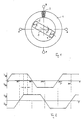
- Figur 1 zeigt schematisch eine Induktionsmaschine mit einem Stator und einem Rotor;
Figur 2 zeigt schematisch über der Zeit den ausgangsseitigen Spannungsverlauf der Induktiionsmaschine nach Fig. 1.
- Figure 1 shows schematically an induction machine with a stator and a rotor;
- FIG. 2 shows schematically over time the voltage profile of the induction machine according to FIG. 1 on the output side.
In Fig. 1 ist der Stator 1 schematisch als Ringkern wiedergegeben, der Windung an Windung gleichförmig mit einer Wicklung 2 versehen ist. Diese Wicklung 2 hat in dem wiedergegebenen Beispiel bei einem 2-polig ausgeführten Rotor 3 Anzapfungen 6,7,8,9, die jeweils um 90° mechanisch verseezt angeordnet sind. Die Anzapfungen 6,7,8,9 sind schematisch als Schlaufen dargestellt. Aus der Figur ist nicht entnehm bar, daß die Wicklung 2 endlos ausgeführt ist, d.h. daß der sich wicklungstechnisch ergebende Anfang mit dem Ende der Wicklung 2 verbunden ist.In Fig. 1, the stator 1 is shown schematically as a ring core which is provided with a winding 2 uniformly from winding to winding. In the example shown, this
Der Rotor 3 trägt zwei Magnete 4,5, deren Durchflutung den Luftspalt zwischen den Magneten 4,5 und dem Stator 1 durchsetzt. Sie teilt sich dort in zwei Teilflüsse auf, die den Stator in beiden Hälften durchsetzen.The
In der 2-poligen Konfiguration der Fig. 1 ist beispielhaft eine Polfolge Nord-Süd-Nord-Süd gewählt. Es ergibt sich somit ein erster Teilfluß, der sich von dem rechts wiedergegebenen Südpol S über den oberen Teil des Ringkernes zum linken Nordpol N erstreckt und andererseits ein zweiter Teilfluß, der sich vom rechten Südpol S durch den unteren Teil des Stators zum links oben wiedergegebenen Nordpol N fortsetzt.In the 2-pole configuration of FIG. 1, a pole sequence north-south-north-south is selected as an example. This results in a first partial flow that extends from the south pole S shown on the right over the upper part of the toroid to the left north pole N and, on the other hand, a second partial flow that extends from the right south pole S through the lower part of the stator to the north pole shown at the top left N continues.
Der Drehwinkel des Rotors ist mit φ bezeichnet.The angle of rotation of the rotor is denoted by φ.
Im oberen Teil der Fig.2 ist über dem Drehwinkel φ der Verlauf einer Spannung U₆₈ aufgetragen, die an den Anzapfungen 6 und 8 abgreifbar ist. In der unteren Hälfte der Figur 2 ist entsprechend die Spannung U₇₉ wiedergegeben, die an den Anzapfungen 7 und 9 bei einer Drehung des Rotors 3 auftritt.In the upper part of FIG. 2, the course of a voltage U₆₈ is plotted over the angle of rotation φ, which can be tapped off at the taps 6 and 8. In the lower half of FIG. 2, the voltage U₇₉ is correspondingly shown, which occurs at the taps 7 and 9 when the
Im folgenden wird anhand der Figuren 1 und 2 die Funktion der Induktionsmaschine beschrieben, wenn sie beispielhaft als Tachometerdynamo eingesetzt ist.The function of the induction machine is described below with reference to FIGS. 1 and 2 when it is used as an example as a tachometer dynamo.
Wenn sich der Rotor 3 dreht - beispielsweise wenn er unmittelbar oder mittelbar an eine Antriebswelle eines Elektromotors gekuppelt ist (nicht dargestellt) - so werden die Windungen der Wicklung 2 von einem magnetischen Feld geschnitten. Eine Windung umfaßt einen magnetischen Fluß Ø , der stetig mit der Zeit, d.h. dem Drehwinkel des Rotors 3 ansteigt. Die induzierte Spannung ist dann nach der Gleichung
In den Bereichen, in welchen die Magnete 4,5 an einer der Anzapfungen 6,7,8,9 vorbeilaufen, sinkt die induzierte Spannung jeweils auf Null ab, um ihre Polarität umzukehren. Solange bei einer Annäherung an eine der Anzapfungen der Drehwinkel kleiner ist als der halbe Öffnungswinkel des Magnetpoles des Rotors,sinkt die Spannung stetig bis auf Null ab. Bei Entfernen von der Anzapfung steigt dann die Spannung entsprechend an, bis der Drehwinkel φ größer ist als der halbe Öffnungswinkel der Magnetpoles. Solange der Drehwinkel φ größer ist als der Öffnungswinkel hat die solcherart induzierte Spannung einen konstanten Verlauf.In the areas in which the
Wie die Figuren erkennen lassen, wird bei einem Drehwinkel von φ = 0°, wenn der Rotor 3 in Richtung der Anzapfungen 6 und 8 steht, keine Spannung induziert, da sich die Teilflüsse symmetrisch zu den Anzapfungen 6 und 8 auf den oberen und den unteren Teil des Ringkernes erstrecken. Dabei ist gleichgültig, ob man die untere Wicklungshälfte oder die obere Wicklungshälfte auf dem Wege von der Anzapfung 6 zur Anzapfung 8 betrachtet. Die Spannung, die induziert wird, ist auf beiden Wegen identisch, da jeweils die gleiche Spannung induziert wird, wenn sich der Südpol des Magneten 4 vom Anschluß 6 entfernt und sich gleichzeitig der außenliegende Nordpol des Magneten 5 auf die Anzapfung 6 zubewegt. Da die Spannungen auf beiden Wegen identisch sind und diese Betrachtung sinngemäß auch für die Anzapfungen 7 und 9 gilt, kann die Spule in sich kurzgeschlossen sein. Die zwischen den paarweise zusammengehörenden Anzapfungen abegriffenen Trapezspannungen werden über elektronische Schalter zu einer Gleichspannung zusammengeschaltet, die in den Figuren nich wiedergegeben sind. Aus der Figur 2 geht hervor, daß in dem wiedergegebenen Beispiel zunächst die Spannung u₆₈ angeschaltet wird. Dann wird elektronisch auf die Spannung u₇₉ umgeschaltet. Darauf folgt die Anschaltung der Spannung u₈₆, die zur Spannung u₆₈ invertiert ist, um anschließend auf die invertierte Spannung u₉₇ zurückzugreifen. Eine mit α gekennzeichnete Überlappung der Spannungen u₆₈ und u₇₉ und der zugehörigen invertierten Spannungen u₈₆ und u₉₇, die zur einwandfreien Funktion der nachfolgenden elektronischen Schaltung erforderlich ist, wird durch die Wahl des Öffnungswinkels bzw. Polbedeckungswinkels des Rotors 3 erreicht. Diese Überlappung betrifft jeweils die konstanten Anteile aufeinanderfolgender Trapezspannungen. Sie bewirkt, daß aus den Trapezspannungen eine Lückenlose Gleichspannung abgeleitet werden kann.As can be seen from the figures, at a rotation angle of φ = 0 °, when the
Obwohl die Erfindung anhand einer Induktionsmaschine mit einer einzigen Windung 2 und mit einem zweipoligen Polrad beispielhaft erläutert ist, sind ohne weiteres auch n-polige Ausführungen realisierbar. Dann sind die Anzapfungen 6,7,8,9 unter einem Winkel von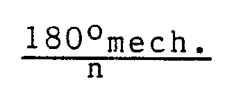

Abschließend ist anzuführen, daß die erfindungsgemäße Induktionsmaschine auch als Motor betrieben werden kann, der sich gleichförmig mit konstanten Drehmoment dreht, wenn trapezförmige Spannungen - entsprechend der Figur 2 - an die Anzapfungen 6,7,8,9 angelegt werden.In conclusion, it should be mentioned that the induction machine according to the invention can also be operated as a motor which rotates uniformly with constant torque when trapezoidal voltages - corresponding to FIG. 2 - are applied to the taps 6, 7, 8, 9.
Claims (11)
dadurch gekennzeichnet , daß der Stator (1) mind. eine in sich kurzgeschlossene, über einen zum Rotor konzentrischen Ringkern gleichmäßig verteilte Wicklung (2) aufweist, die mit mind. zwei in Umfangsrichtung gegeneinander versetzten Anzapfungen (6,7,8,9) zum Abgriff der Trapezspannungen versehen ist.1. Brushless n-phase and n-pole induction machine, for example DC voltage tachometer dynamo, for generating trapezoidal voltages, with a rotor having magnets and with a stator carrying at least one winding,
characterized in that the stator (1) has at least one short-circuited winding (2) which is uniformly distributed over an annular core concentric with the rotor and which has at least two taps (6, 7, 8, 9) offset in the circumferential direction Tapping the trapezoidal voltages is provided.
dadurch gekennzeichnet , daß die Anzapfungen (6,7,8,9) paarweise zugeordnet mit einem Versatz von jeweils 180° mechanisch angeordnet sind.2. Induction machine according to claim 1,
characterized in that the taps (6, 7, 8, 9) are mechanically arranged in pairs with an offset of 180 ° each.
dadurch gekennzeichnet , daß bei n Polen n·2 Anzapfungen (6,7,8,9) vorhanden sind, die paarweise um

characterized in that for n poles there are n · 2 taps (6,7,8,9) which change in pairs
dadurch gekennzeichnet , daß m Wicklungen (2) vorhanden sind, und daß die Anzapfungen der Wicklungen (2) untereinander um

characterized in that there are m windings (2), and in that the taps of the windings (2) with one another
dadurch gekennzeichnet , daß eine Wicklung (2) vorhanden ist, und daß der Rotor (3) n=2 Pole aufweist.5. Induction machine according to one of the preceding claims,
characterized in that a winding (2) is present and in that the rotor (3) has n = 2 poles.
dadurch gekennzeichnet , daß eine Wicklung (2) und ein Rotor (3) mit n=4 Polen vorhanden sind.6. Induction machine according to one of claims 1 to 4,
characterized in that there is a winding (2) and a rotor (3) with n = 4 poles.
dadurch gekennzeichnet , daß m=2 Wicklungen (2) vorhanden sind, und der Rotor (3) n=2 Pole aufweist.7. induction machine according to one of claims 1 to 4,
characterized in that m = 2 windings (2) are present and the rotor (3) has n = 2 poles.
dadurch gekennzeichnet , daß Anfang und Ende einer Wicklung (2) in einer Anzapfung (6,7,8,9) kurzgeschlossen sind.8. Induction machine according to one of the preceding claims,
characterized in that the beginning and end of a winding (2) are short-circuited in a tap (6, 7, 8, 9).
dadurch gekennzeichnet , daß der Rotor (3) einen Polbedeckungswinkel aufweist, der so gewählt ist, daß sich bezüglich einer Anzapfung nacheinander induzierte Trapezspannungen in ihrem konstanten Anteil überlappen.9. Induction machine according to one of the preceding claims,
characterized in that the rotor (3) has a pole coverage angle which is selected such that trapezoidal voltages successively induced overlap with respect to one another in their constant portion.
dadurch gekennzeichnet , daß der Stator (1) um den Rotor (3) herum angeordnet ist und daß der Ringkern aus einem Blechpaket besteht.10. Induction machine according to one of the preceding claims,
characterized in that the stator (1) is arranged around the rotor (3) and in that the ring core consists of a laminated core.
dadurch gekennzeichnet , daß die Magnete (3,4,) des Rotors (3) seitlich am Stator (1) angreifen, und daß der Ringkern aus einem aufgewickelten Blechstreifen besteht.11. Induction machine according to one of claims 1 to 9,
characterized in that the magnets (3, 4,) of the rotor (3) act laterally on the stator (1), and in that the toroid consists of a coiled sheet metal strip.
Applications Claiming Priority (2)
| Application Number | Priority Date | Filing Date | Title |
|---|---|---|---|
| DE19853532101 DE3532101A1 (en) | 1985-09-09 | 1985-09-09 | BRUSHLESS INDUCTION MACHINE |
| DE3532101 | 1985-09-09 |
Publications (2)
| Publication Number | Publication Date |
|---|---|
| EP0214385A2 true EP0214385A2 (en) | 1987-03-18 |
| EP0214385A3 EP0214385A3 (en) | 1987-12-09 |
Family
ID=6280456
Family Applications (1)
| Application Number | Title | Priority Date | Filing Date |
|---|---|---|---|
| EP86108668A Withdrawn EP0214385A3 (en) | 1985-09-09 | 1986-06-25 | Brushless induction machine |
Country Status (2)
| Country | Link |
|---|---|
| EP (1) | EP0214385A3 (en) |
| DE (1) | DE3532101A1 (en) |
Family Cites Families (8)
| Publication number | Priority date | Publication date | Assignee | Title |
|---|---|---|---|---|
| US2416341A (en) * | 1943-06-25 | 1947-02-25 | Bell Telephone Labor Inc | Pure sinusoidal wave generator |
| GB1202575A (en) * | 1966-09-13 | 1970-08-19 | John Byrne | Improvements in or relating to electric tachogenerators |
| GB1417066A (en) * | 1972-03-06 | 1975-12-10 | Byrne J | Tachogenerators |
| US4276482A (en) * | 1977-06-03 | 1981-06-30 | Otis Engineering Corporation | Line flow electric power generator |
| JPS57180348A (en) * | 1981-04-27 | 1982-11-06 | Fuji Electric Co Ltd | Rotation detector |
| JPS57182172A (en) * | 1981-05-02 | 1982-11-09 | Fuji Electric Co Ltd | Detector for speed of revolution |
| WO1984000422A1 (en) * | 1982-07-06 | 1984-02-02 | Kenneth S Kordik | An improved magnetic rotational velocity sensor |
| JPS6059954A (en) * | 1983-09-09 | 1985-04-06 | Tokyo Keiki Co Ltd | Toroidal coil type rotary electric machine |
-
1985
- 1985-09-09 DE DE19853532101 patent/DE3532101A1/en not_active Withdrawn
-
1986
- 1986-06-25 EP EP86108668A patent/EP0214385A3/en not_active Withdrawn
Also Published As
| Publication number | Publication date |
|---|---|
| EP0214385A3 (en) | 1987-12-09 |
| DE3532101A1 (en) | 1987-03-19 |
Similar Documents
| Publication | Publication Date | Title |
|---|---|---|
| DE3006034C2 (en) | Motor control system for a brushless electric motor | |
| DE60218935T2 (en) | Rotating electrical machine with three-phase ring coils and permanent magnets | |
| DE2515133C3 (en) | Reluctance machine arrangement | |
| DE69716086T2 (en) | ELECTRICAL MACHINES | |
| DE2802753C2 (en) | Synchronous machine | |
| DE3838579C2 (en) | ||
| EP1708338A1 (en) | Electric machine | |
| EP1064712A1 (en) | Multi-phase transverse flux machine | |
| DE3012833C2 (en) | ||
| DE2756575C2 (en) | ||
| WO1991003866A1 (en) | Commutator motor | |
| WO1993010594A1 (en) | Linear motor or generator and stator therefor | |
| DE1763294B2 (en) | ARRANGEMENT FOR THE FORMATION OF A SPEED PROPORTIONAL VOLTAGE | |
| DE69513453T2 (en) | BRUSHLESS DC MOTOR | |
| DE4419780A1 (en) | Annular stator with segmented toroidal winding for rotating machine | |
| EP0216998A1 (en) | Brushless induction machine | |
| DE3037724C2 (en) | DC motor | |
| EP0214385A2 (en) | Brushless induction machine | |
| DE2161409A1 (en) | Electric machine | |
| DE2452082A1 (en) | COLLECTORLESS DC MOTOR WITH SINGLE STATOR WINDING | |
| EP0216202B2 (en) | Electric motor | |
| DE2221099A1 (en) | Electromagnetic device for determining the runner position | |
| EP0193067A1 (en) | Three-phase motor powered by a multiphase direct converter arrangement | |
| DE1290242B (en) | Electric machine with variable magnetic resistance | |
| DE2556582A1 (en) | METHOD AND MOTOR DEVICE FOR GENERATING HIGH SPEEDS |
Legal Events
| Date | Code | Title | Description |
|---|---|---|---|
| PUAI | Public reference made under article 153(3) epc to a published international application that has entered the european phase |
Free format text: ORIGINAL CODE: 0009012 |
|
| AK | Designated contracting states |
Kind code of ref document: A2 Designated state(s): AT BE CH DE FR GB IT LI LU NL SE |
|
| RBV | Designated contracting states (corrected) |
Designated state(s): DE FR GB IT |
|
| PUAL | Search report despatched |
Free format text: ORIGINAL CODE: 0009013 |
|
| AK | Designated contracting states |
Kind code of ref document: A3 Designated state(s): DE FR GB IT |
|
| STAA | Information on the status of an ep patent application or granted ep patent |
Free format text: STATUS: THE APPLICATION IS DEEMED TO BE WITHDRAWN |
|
| 18D | Application deemed to be withdrawn |
Effective date: 19880610 |
|
| RIN1 | Information on inventor provided before grant (corrected) |
Inventor name: SAWITZKI, UWE, DIPL.-ING. |