EP0214385A2 - Machine à induction sans balais - Google Patents
Machine à induction sans balais Download PDFInfo
- Publication number
- EP0214385A2 EP0214385A2 EP86108668A EP86108668A EP0214385A2 EP 0214385 A2 EP0214385 A2 EP 0214385A2 EP 86108668 A EP86108668 A EP 86108668A EP 86108668 A EP86108668 A EP 86108668A EP 0214385 A2 EP0214385 A2 EP 0214385A2
- Authority
- EP
- European Patent Office
- Prior art keywords
- induction machine
- rotor
- machine according
- winding
- taps
- Prior art date
- Legal status (The legal status is an assumption and is not a legal conclusion. Google has not performed a legal analysis and makes no representation as to the accuracy of the status listed.)
- Withdrawn
Links
Images
Classifications
-
- H—ELECTRICITY
- H02—GENERATION; CONVERSION OR DISTRIBUTION OF ELECTRIC POWER
- H02K—DYNAMO-ELECTRIC MACHINES
- H02K39/00—Generators specially adapted for producing a desired non-sinusoidal waveform
-
- G—PHYSICS
- G01—MEASURING; TESTING
- G01P—MEASURING LINEAR OR ANGULAR SPEED, ACCELERATION, DECELERATION, OR SHOCK; INDICATING PRESENCE, ABSENCE, OR DIRECTION, OF MOVEMENT
- G01P3/00—Measuring linear or angular speed; Measuring differences of linear or angular speeds
- G01P3/42—Devices characterised by the use of electric or magnetic means
- G01P3/44—Devices characterised by the use of electric or magnetic means for measuring angular speed
- G01P3/46—Devices characterised by the use of electric or magnetic means for measuring angular speed by measuring amplitude of generated current or voltage
- G01P3/465—Devices characterised by the use of electric or magnetic means for measuring angular speed by measuring amplitude of generated current or voltage by using dynamo-electro tachometers or electric generator
-
- H—ELECTRICITY
- H02—GENERATION; CONVERSION OR DISTRIBUTION OF ELECTRIC POWER
- H02K—DYNAMO-ELECTRIC MACHINES
- H02K21/00—Synchronous motors having permanent magnets; Synchronous generators having permanent magnets
- H02K21/12—Synchronous motors having permanent magnets; Synchronous generators having permanent magnets with stationary armatures and rotating magnets
- H02K21/14—Synchronous motors having permanent magnets; Synchronous generators having permanent magnets with stationary armatures and rotating magnets with magnets rotating within the armatures
Definitions
- the invention relates to a brushless n-phase and n-pole induction machine, for example a DC tachometer dynamo, for generating trapezoidal voltages, with a rotor having magnets and with a stator carrying at least one winding.
- a brushless n-phase and n-pole induction machine for example a DC tachometer dynamo, for generating trapezoidal voltages, with a rotor having magnets and with a stator carrying at least one winding.
- Induction machines for generating trapezoidal output voltages are used in a wide variety of applications in measurement, control and drive technology, where it is necessary to have a DC signal proportional to the speed.
- High demands are made, for example, on the control of drives that usually run at an exact speed, such as centrifuges, machine tools and elevators, and in which the speed must be variable over a wide range.
- a brushless induction machine of the type described at the outset is known from German utility model G 83 24 702, with multiphase, phase-shiftable windings located in an air gap between the rotor and stator.
- Each phase of the winding has four coils, each of which is divided into two sub-coils lying one above the other in the radial direction.
- the coils are arranged in a bobbin in such a way that the two partial coils of one phase lie between the two coils of another phase that follow in the circumferential direction at the intersections and that the two partial coil pairs overlap there.
- this known induction machine has the disadvantage that the windings have to be inserted very precisely onto the plastic bobbin in the air gap with a relatively large production outlay.
- the invention is therefore based on the object of specifying an induction machine of the type mentioned at the outset, which is provided with simply shaped pole pieces and thereby has a homogeneous magnetic field.
- stator has at least one short-circuited winding which is uniformly distributed over an annular core which is concentric with the rotor and which is provided with at least two taps which are offset in the circumferential direction to tap the trapezoidal voltages.
- the principle of the invention is that the homogeneity required to generate the constant part of the trapezoidal voltage is not placed in the magnetic field, but in the winding.
- the same number of turns per time unit occur in the magnetic field when the rotor rotates, as turns emerge from the magnetic field on its rear side. Since the windings are distributed uniformly over the toroidal core according to the invention, the same number of windings are always newly cut by the magnetic field per unit of time.
- the invention has the advantage that precision tachometer dynamos can be produced, which are characterized by a ripple of less than 1.5%. Furthermore, asymmetries of the magnetic field in the air gap which may arise due to manufacturing tolerances and which can lead to slight differences in the voltages induced by the rotor magnets can be compensated for by the short-circuit currents caused in the winding.
- the taps are preferably mechanically arranged in pairs at an offset of 180 ° each. In this way, two mutually inverted trapezoidal voltages can be tapped, each of which extends electrically over 180 °.
- n ⁇ 2 taps are present in n poles, which belong together in pairs are offset.
- the frequency of the trapezoidal voltages on the output side is correspondingly increased.
- n 4 poles are present for a winding.
- An advantageous further development of the invention consists in the fact that the pole coverage angle of the roto is selected such that the trapezoidal voltages induced one after the other overlap in their constant proportion.
- stator is arranged concentrically around the rotor and consists of an annular sheet stack.
- stator is arranged on the side of the rotor and has an annular core made of a coiled sheet metal strip.
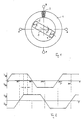
- the stator 1 is shown schematically as a ring core which is provided with a winding 2 uniformly from winding to winding.
- this winding 2 has 3 taps 6, 7, 8, 9 in a 2-pole rotor, which are each mechanically staggered by 90 °.
- the taps 6,7,8,9 are shown schematically as loops. Not removed from the figure bar that the winding 2 is endless, that is, that the result in terms of winding technology is connected to the end of the winding 2.
- the rotor 3 carries two magnets 4, 5, the flow of which penetrates the air gap between the magnets 4, 5 and the stator 1. There it divides into two partial flows, which penetrate the stator in both halves.
- a pole sequence north-south-north-south is selected as an example. This results in a first partial flow that extends from the south pole S shown on the right over the upper part of the toroid to the left north pole N and, on the other hand, a second partial flow that extends from the right south pole S through the lower part of the stator to the north pole shown at the top left N continues.
- the angle of rotation of the rotor is denoted by ⁇ .
- induction machine The function of the induction machine is described below with reference to FIGS. 1 and 2 when it is used as an example as a tachometer dynamo.
- the windings of the winding 2 are cut by a magnetic field.
- One turn comprises a magnetic flux ⁇ , which increases steadily with time, ie the angle of rotation of the rotor 3.
- the induced voltage is then according to the equation constant.
- the magnets 4, 5 rotate, the same number of turns of the winding 2 enter the magnetic field as the turns on the back emerge from the magnetic field. Since, according to the invention, the windings are distributed uniformly over the ring core of the stator, the same number of windings are always cut anew in the magnetic field per unit of time first induced the voltage u68.
- the voltage u79 is induced out of phase and can be tapped at the taps 7, 9.
- the induced voltage drops to zero in order to reverse its polarity.
- the angle of rotation is smaller than half the opening angle of the magnetic pole of the rotor when approaching one of the taps, the voltage drops steadily to zero.
- the tap is removed, the voltage rises accordingly until the angle of rotation ⁇ is greater than half the opening angle of the magnetic poles.
- the angle of rotation ⁇ is greater than the opening angle has a constant course of the voltage induced in this way.
- the coil can be short-circuited in itself.
- the trapezoidal voltages tapped between the taps belonging together in pairs are connected to a DC voltage via electronic switches, which are not shown in the figures. It can be seen from FIG. 2 that the voltage u capital is first switched on in the example shown. Then the voltage u79 is switched electronically. This is followed by the connection of the voltage u86, which is inverted to the voltage u68, in order to then use the inverted voltage u97.
- n-pole versions can also be implemented without difficulty.
- the induction machine according to the invention can also be operated as a motor which rotates uniformly with constant torque when trapezoidal voltages - corresponding to FIG. 2 - are applied to the taps 6, 7, 8, 9.
Landscapes
- Engineering & Computer Science (AREA)
- Power Engineering (AREA)
- Physics & Mathematics (AREA)
- General Physics & Mathematics (AREA)
- Permanent Magnet Type Synchronous Machine (AREA)
- Iron Core Of Rotating Electric Machines (AREA)
- Synchronous Machinery (AREA)
Applications Claiming Priority (2)
| Application Number | Priority Date | Filing Date | Title |
|---|---|---|---|
| DE19853532101 DE3532101A1 (de) | 1985-09-09 | 1985-09-09 | Buerstenlose induktionsmaschine |
| DE3532101 | 1985-09-09 |
Publications (2)
| Publication Number | Publication Date |
|---|---|
| EP0214385A2 true EP0214385A2 (fr) | 1987-03-18 |
| EP0214385A3 EP0214385A3 (fr) | 1987-12-09 |
Family
ID=6280456
Family Applications (1)
| Application Number | Title | Priority Date | Filing Date |
|---|---|---|---|
| EP86108668A Withdrawn EP0214385A3 (fr) | 1985-09-09 | 1986-06-25 | Machine à induction sans balais |
Country Status (2)
| Country | Link |
|---|---|
| EP (1) | EP0214385A3 (fr) |
| DE (1) | DE3532101A1 (fr) |
Family Cites Families (8)
| Publication number | Priority date | Publication date | Assignee | Title |
|---|---|---|---|---|
| US2416341A (en) * | 1943-06-25 | 1947-02-25 | Bell Telephone Labor Inc | Pure sinusoidal wave generator |
| GB1202575A (en) * | 1966-09-13 | 1970-08-19 | John Byrne | Improvements in or relating to electric tachogenerators |
| GB1417066A (en) * | 1972-03-06 | 1975-12-10 | Byrne J | Tachogenerators |
| US4276482A (en) * | 1977-06-03 | 1981-06-30 | Otis Engineering Corporation | Line flow electric power generator |
| JPS57180348A (en) * | 1981-04-27 | 1982-11-06 | Fuji Electric Co Ltd | Rotation detector |
| JPS57182172A (en) * | 1981-05-02 | 1982-11-09 | Fuji Electric Co Ltd | Detector for speed of revolution |
| WO1984000422A1 (fr) * | 1982-07-06 | 1984-02-02 | Kenneth S Kordik | Detecteur magnetique ameliore de vitesse de rotation |
| JPS6059954A (ja) * | 1983-09-09 | 1985-04-06 | Tokyo Keiki Co Ltd | トロイダルコイル型回転電機 |
-
1985
- 1985-09-09 DE DE19853532101 patent/DE3532101A1/de not_active Withdrawn
-
1986
- 1986-06-25 EP EP86108668A patent/EP0214385A3/fr not_active Withdrawn
Also Published As
| Publication number | Publication date |
|---|---|
| EP0214385A3 (fr) | 1987-12-09 |
| DE3532101A1 (de) | 1987-03-19 |
Similar Documents
| Publication | Publication Date | Title |
|---|---|---|
| DE3006034C2 (de) | Motorsteuersystem für einen bürstenlosen Elektromotor | |
| DE60218935T2 (de) | Drehende elektrische Maschine mit Drehstromringspulen und Dauermagneten | |
| DE2515133C3 (de) | Reluktanzmaschinenanordnung | |
| DE69716086T2 (de) | Elektrische maschinen | |
| DE2802753C2 (de) | Synchronmaschine | |
| DE3838579C2 (fr) | ||
| EP1708338A1 (fr) | Machine électrique | |
| EP1064712A1 (fr) | Moteur a flux transversal polyphase | |
| DE3012833C2 (fr) | ||
| DE2756575C2 (fr) | ||
| WO1991003866A1 (fr) | Moteur a collecteur | |
| WO1993010594A1 (fr) | Moteur lineaire ou generatrice lineaire ainsi que stator pour un tel appareil | |
| DE1763294B2 (de) | Anordnung zur bildung einer drehzahlproportionalen spannung | |
| DE69513453T2 (de) | Bürstenloser gleichstrommotor | |
| DE4419780A1 (de) | Ringförmiger Stator für elektrodynamische Drehmaschine | |
| EP0216998A1 (fr) | Machine à induction sans balais | |
| DE3037724C2 (de) | Gleichstrommotor | |
| EP0214385A2 (fr) | Machine à induction sans balais | |
| DE2161409A1 (de) | Elektrische Maschine | |
| DE2452082A1 (de) | Kollektorloser gleichstrommotor mit einstraengiger statorwicklung | |
| EP0216202B2 (fr) | Moteur électrique | |
| DE2221099A1 (de) | Elektromagnetische Vorrichtung zur Bestimmung der Laeuferstellung | |
| EP0193067A1 (fr) | Moteur à courant triphasé alimenté par un dispositif de conversion multiphasé | |
| DE1290242B (de) | Elektrische Maschine mit veraenderlichem magnetischem Widerstand | |
| DE2556582A1 (de) | Verfahren und motor-vorrichtung zur erzeugung hoher drehzahlen |
Legal Events
| Date | Code | Title | Description |
|---|---|---|---|
| PUAI | Public reference made under article 153(3) epc to a published international application that has entered the european phase |
Free format text: ORIGINAL CODE: 0009012 |
|
| AK | Designated contracting states |
Kind code of ref document: A2 Designated state(s): AT BE CH DE FR GB IT LI LU NL SE |
|
| RBV | Designated contracting states (corrected) |
Designated state(s): DE FR GB IT |
|
| PUAL | Search report despatched |
Free format text: ORIGINAL CODE: 0009013 |
|
| AK | Designated contracting states |
Kind code of ref document: A3 Designated state(s): DE FR GB IT |
|
| STAA | Information on the status of an ep patent application or granted ep patent |
Free format text: STATUS: THE APPLICATION IS DEEMED TO BE WITHDRAWN |
|
| 18D | Application deemed to be withdrawn |
Effective date: 19880610 |
|
| RIN1 | Information on inventor provided before grant (corrected) |
Inventor name: SAWITZKI, UWE, DIPL.-ING. |