EP0214525A1 - Véhicule sous-marin - Google Patents
Véhicule sous-marin Download PDFInfo
- Publication number
- EP0214525A1 EP0214525A1 EP86111539A EP86111539A EP0214525A1 EP 0214525 A1 EP0214525 A1 EP 0214525A1 EP 86111539 A EP86111539 A EP 86111539A EP 86111539 A EP86111539 A EP 86111539A EP 0214525 A1 EP0214525 A1 EP 0214525A1
- Authority
- EP
- European Patent Office
- Prior art keywords
- vehicle body
- streamer
- vehicle according
- holding
- underwater vehicle
- Prior art date
- Legal status (The legal status is an assumption and is not a legal conclusion. Google has not performed a legal analysis and makes no representation as to the accuracy of the status listed.)
- Granted
Links
- 239000011248 coating agent Substances 0.000 claims description 4
- 238000000576 coating method Methods 0.000 claims description 4
- 125000006850 spacer group Chemical group 0.000 claims description 4
- XLYOFNOQVPJJNP-UHFFFAOYSA-N water Substances O XLYOFNOQVPJJNP-UHFFFAOYSA-N 0.000 claims description 4
- 230000005855 radiation Effects 0.000 claims description 3
- 206010016322 Feeling abnormal Diseases 0.000 abstract 1
- 230000000717 retained effect Effects 0.000 abstract 1
- 230000006378 damage Effects 0.000 description 4
- 238000010276 construction Methods 0.000 description 2
- 239000007788 liquid Substances 0.000 description 2
- 238000009420 retrofitting Methods 0.000 description 2
- 238000003491 array Methods 0.000 description 1
- 239000011324 bead Substances 0.000 description 1
- 230000005540 biological transmission Effects 0.000 description 1
- 238000006073 displacement reaction Methods 0.000 description 1
- 238000012423 maintenance Methods 0.000 description 1
- 239000000725 suspension Substances 0.000 description 1
- 230000001960 triggered effect Effects 0.000 description 1
Images



Classifications
-
- B—PERFORMING OPERATIONS; TRANSPORTING
- B63—SHIPS OR OTHER WATERBORNE VESSELS; RELATED EQUIPMENT
- B63G—OFFENSIVE OR DEFENSIVE ARRANGEMENTS ON VESSELS; MINE-LAYING; MINE-SWEEPING; SUBMARINES; AIRCRAFT CARRIERS
- B63G8/00—Underwater vessels, e.g. submarines; Equipment specially adapted therefor
- B63G8/39—Arrangements of sonic watch equipment, e.g. low-frequency, sonar
-
- G—PHYSICS
- G10—MUSICAL INSTRUMENTS; ACOUSTICS
- G10K—SOUND-PRODUCING DEVICES; METHODS OR DEVICES FOR PROTECTING AGAINST, OR FOR DAMPING, NOISE OR OTHER ACOUSTIC WAVES IN GENERAL; ACOUSTICS NOT OTHERWISE PROVIDED FOR
- G10K11/00—Methods or devices for transmitting, conducting or directing sound in general; Methods or devices for protecting against, or for damping, noise or other acoustic waves in general
- G10K11/004—Mounting transducers, e.g. provided with mechanical moving or orienting device
- G10K11/006—Transducer mounting in underwater equipment, e.g. sonobuoys
Definitions
- the invention relates to an underwater vehicle, in particular a submarine, with at least one side antenna arranged on the vehicle body and extending in the longitudinal direction of the vehicle for receiving acoustic signals.
- each side antenna arranged on port and starboard also called flank array sonar (FAS)
- FAS flank array sonar
- Noise sources in the underwater vehicle such as drive motors and the like, generate not insignificant noises which are transmitted via the vehicle body to the hydrophones of the side antennas attached to the vehicle body. Since this so-called structure-borne noise largely covers the useful sound received by the hydrophones as background noise, structure-borne noise decoupling of the hydrophones is essential. Such decoupling of structure-borne noise by individual suspension of the hydrophones on the vehicle body is very complex and almost impossible to retrofit for underwater vehicles that have already been completed for reasons of cost.
- the invention is based on the object, in a watercraft, in particular a submarine, with the side antenna to construct the latter in such a way and to connect it to the vehicle body that a technically simple attachment of the side antenna to the vehicle body the individual hydrophones are achieved while maintaining good structure-borne noise decoupling.
- This constructive training is intended to allow the side antenna to be retrofitted to the vehicle body that has already been completed without further ado and at a reasonable cost.
- the well-known hydrophone streamer which in its construction z. B. is shown and described in US Pat. No. 4,160,229 and has found its first use as a seismic measuring cable, consists of a hydrophone chain in which the individual hydrophones are coupled between the spacing elements in a completely decoupled manner.
- the spacer elements and the individual hydrophones are surrounded by a sheath, and the electrical connection lines to the individual hydrophones are routed as a wire harness in the interior of the sheath.
- the cover which is closed at the end, is filled with a liquid which, on the one hand, acoustically decouples the individual hydrophones from one another and, on the other hand, is used to make the streamer buoyancy-neutral.
- Such hydrophone streamers are currently also used in large lengths as tow antennas or towed arrays drawn by submarines in the water.
- the construction of the side antenna according to the invention and its attachment to the vehicle body ensures very good structure-borne noise decoupling of the individual hydrophones.
- the side antenna can be easily retrofitted to the vehicle body that has already been manufactured, and at such low retrofitting costs that retrofitting of submarines with side antennas is very attractive.
- An advantageous embodiment of the invention results from claim 2. This measure results in a very simple mounting of the streamer on the vehicle body with good structure-borne noise decoupling. This structure-borne noise decoupling is further improved in the exemplary embodiment of the invention according to claim 4 in that the spacer elements of the hydrophone streamer are additionally largely elastically suspended on the holding members fastened to the vehicle body.
- An advantageous embodiment of the invention also results from claim 5.
- the coating of the vehicle body in the region of the streamer results in attenuation of the signals acoustically emitted by the side wall.
- Such acoustic signal radiation can be triggered both by natural vibrations of the side wall and by reflections of useful signals on the side wall.
- An advantageous embodiment of the invention results from claim 8.
- These measures make it possible to significantly increase the distance from the side antenna to the vehicle body and at the same time the maneuverability of the vehicle, for. B. when putting on, not to impair or to effectively protect the side antennas from necessary damage or destruction when maneuvering the vehicle.
- the distance of the side antenna of approx. 60 - 100cm from the vehicle body that can be achieved with the specified measures is sufficient to almost completely eliminate the influence of the vehicle body on noise and to ensure a very good S / N ratio of the side antenna.
- the submarine shown in FIG. 1 as an example of an underwater vehicle has, in a known manner, an elongated hull 10 and an entry tower 11 protruding therefrom.On port and starboard, a side antenna 12 is attached to the hull 10 slightly below the center line, of which in Fig. 1 only the starboard side antenna can be seen.
- the side antenna extends over a substantial part of the longitudinal extent of the hull 10 and is preferably located exclusively in the rectilinearly stretched area of the hull 10.
- the side antenna 12 which has a length of approximately 30 m, consists of a hydrophone streamer 13 enclosed by an enveloping body 14 (FIG. 2).
- a hydrophone streamer 13 also known as a hydrophone drag chain or seismic measuring cable, is known per se.
- An embodiment of such a hydrophone streamer 13 is described in US Pat. No. 4,160,229 or in DE-OS 29 41 028.
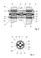
- the hydrophone streamer 13 shown here in detail and in section in FIG. 3 is described in DE-OS 27 19 951 (there FIG. 8), so that the structure of the hydrophone streamer 13 is only briefly explained here for the sake of clarity.
- the hydrophone streamer 13 has a hose jacket 15 which is supported by shaped pieces 16 at certain intervals. These spacer elements formed by the shaped pieces 16 each consist of two prefabricated plastic molded parts 161, 162 with through openings 17, 18 for two line strands 19, 20, in which the connecting lines leading to hydrophones 21 are combined.
- the fittings 161, 162 are on two pull cables 22, 23 at certain intervals, for. B. by clamping sleeves 24, and thus securely held against longitudinal displacement.
- the hydrophones 21 arranged at certain intervals in the hose jacket 15 are each arranged between two shaped pieces 16.
- the hydrophones 21 (FIG. 4), which are cylindrical in design, are seated in a holder 25 clamped on the pull cables 22, 23.
- This holder is simply composed of two resilient halves 251, 252, for example made of plastic, the pull cables 22, 23 of which each half-comprehensive end portions are held together by spring clips 26.
- the middle part of the assembled holder 25 encloses a cylindrical cavity for receiving the hydrophone 21, which is resiliently held therein.
- the hose jacket 15 is filled with liquid, which ensures good acoustic transmission properties between the hydrophones 21 and the hose jacket 15.
- the hydrophone streamer 13 and the holding members 27 with their fasteners 29 are of that Covering body 14 covered, which is completed on both ends and is attached to fastening tabs 31 connected to the foundation 28.
- the outer skin of the hull 10 is provided with a sound-absorbing or sound-absorbing coating 32.
- the coating 32 expediently also covers the foundation 28.
- the side antenna 112 again designed as a hydrophone streamer 113, is attached to two movable holding arms 133, 134.
- a traction cable 135 or 136 engages on each end face of the hydrophone streamer 113.
- the traction cables 135, 136 can be wound up via cable winches (not shown) arranged in the hull 110, so that the hydrophone streamer 113 assumes a largely straight stretch position between the holding arms 133, 134.
- the holding arms 133, 134 are designed to be movable relative to the hull 110.
- a drive mechanism 137 (FIG. 6) engages on each holding arm 133, 134, by means of which the holding arm 133 or 134 can be transferred into two different positions.
- the holding arms 133, 134 are designed as pressure-medium-driven telescopic rods 138 which can be moved in and out in the horizontal direction.
- the drive mechanism 137 is formed by a hydraulic cylinder 139 which is connected to a hydraulic system (not shown) via two separate pressure lines 140, 141. At their free end, the telescopic rods 138 each carry a fastening element 129 encompassing the hydrophone streamer 113.
- the hull 110 consists in a known manner of an inner pressure body 142 and a hull 143 which surrounds the pressure body 142 at a distance.
- the space 144 between the hull 143 and the pressure body 142 is flooded.
- the drive mechanism 137 is expediently arranged in the intermediate space 144 and fastened to the hull 142.
- the holding arms 133, 134 in the form of the telescopic rods 138 pass through recesses 145 in the hull 143.
- the hydrophone streamer 113 is protected between beads 146, 147, which each surround a recess 145 in the hull 143.
- the hydrophone streamer 113 assumes a maximum distance from the hull 110.
- the extension length of the telescopic rods 138 is dimensioned such that the hydrophone streamer 113 is now essentially outside the acoustic near field of sound radiation emanating from the hull 110.
- both holding positions of the holding arms 133, 134 lie in a horizontal plane 148.
- the position of this horizontal plane 148 with respect to the hull 110 is such that the hull 110 has its greatest horizontal width dimension here.
- the hydrophone strea is mer 213 and 313 in turn attached to two with respect to the hull 210 and 310 movable support arms, of which only one of the support arms 233 and 333 can be seen.
- the holding arms are each held on the hull 243 about a horizontal pivot axis 249 pointing in the longitudinal direction of the ship.
- the holding arm 233 is pivoted via a pivoting lever 250, which in turn is driven by a hydraulic cylinder 239.
- FIG. 8 shows the holding arm 233 for the starboard side antenna 212 in its state when it is folded against the hull 210 and the holding arm 233 for the port side antenna 212 in its state when it is folded down from the hull 210.
- the shape of the holding arm 233 is adapted to the curvature of the ship's hull 243, so that it is largely in a form-fitting manner.
- the hydrophone streamer 213 and 313 also lies in the second holding arm position, folded away from the hull 210 and 310, in the horizontal plane 248 and 348, in which the hull 210 and 310 also has its largest width dimension having.
- the hydrophone streamer 213 lies below this horizontal plane 248 and the hydrophone streamer 313 lies above this horizontal plane 348, the latter position being selected such that the hydrophone streamer 313 lies above the water surface 351 when the submarine is exposed.
- the invention is not restricted to the exemplary embodiment described above.
- the hydrophone streamer can also be constructed in a different way, as shown and described here in FIGS. 3 and 4. Practically all commercially available hydrophone streamers with the appropriate length can be used. Also the attachment of the hydrophone streamer to the side wall of the hull is not mandatory. If required for certain purposes, the hydrophone streamer can also be placed along the deck of the hull.
Landscapes
- Engineering & Computer Science (AREA)
- Radar, Positioning & Navigation (AREA)
- Mechanical Engineering (AREA)
- Aviation & Aerospace Engineering (AREA)
- Physics & Mathematics (AREA)
- Acoustics & Sound (AREA)
- Multimedia (AREA)
- Measurement Of Velocity Or Position Using Acoustic Or Ultrasonic Waves (AREA)
- Acyclic And Carbocyclic Compounds In Medicinal Compositions (AREA)
Applications Claiming Priority (2)
| Application Number | Priority Date | Filing Date | Title |
|---|---|---|---|
| DE3532309 | 1985-09-11 | ||
| DE19853532309 DE3532309A1 (de) | 1985-09-11 | 1985-09-11 | Unterwasserfahrzeug |
Publications (2)
| Publication Number | Publication Date |
|---|---|
| EP0214525A1 true EP0214525A1 (fr) | 1987-03-18 |
| EP0214525B1 EP0214525B1 (fr) | 1988-11-09 |
Family
ID=6280595
Family Applications (1)
| Application Number | Title | Priority Date | Filing Date |
|---|---|---|---|
| EP86111539A Expired EP0214525B1 (fr) | 1985-09-11 | 1986-08-20 | Véhicule sous-marin |
Country Status (4)
| Country | Link |
|---|---|
| EP (1) | EP0214525B1 (fr) |
| DE (2) | DE3532309A1 (fr) |
| ES (1) | ES2000882A6 (fr) |
| NO (1) | NO160987C (fr) |
Cited By (8)
| Publication number | Priority date | Publication date | Assignee | Title |
|---|---|---|---|---|
| WO2006015645A1 (fr) | 2004-08-05 | 2006-02-16 | Atlas Elektronik Gmbh | Antenne subaquatique electroacoustique |
| RU2308052C1 (ru) * | 2005-12-28 | 2007-10-10 | Сергей Алексеевич Бахарев | Способ обнаружения, идентификации и определения пространственных координат объектов при всплытии подводного аппарата |
| ITPT20090013A1 (it) * | 2009-09-22 | 2009-12-22 | Pin Craft Srl | Automatismo con cilindro oleodinamico per la movimentazione del rilevatore sonar-sounder subacqueo posto sullo scafo di imbarcazioni di qualunque tipo. |
| WO2010046300A1 (fr) * | 2008-10-20 | 2010-04-29 | Atlas Elektronik Gmbh | Dispositif de fixation d'une antenne sous-marine |
| US20120113757A1 (en) * | 2010-08-04 | 2012-05-10 | Lockheed Martin Corporation | Hull mounted linear sonar array |
| RU2621638C1 (ru) * | 2016-04-15 | 2017-06-06 | Российская Федерация, от имени которой выступает ФОНД ПЕРСПЕКТИВНЫХ ИССЛЕДОВАНИЙ | Способ подводной сейсмической разведки |
| WO2018059613A1 (fr) * | 2016-09-27 | 2018-04-05 | Atlas Elektronik Gmbh | Antenne sous-marine pour engin sous-marin et corps de coque muni d'une telle antenne sous-marine |
| RU2696816C1 (ru) * | 2017-12-07 | 2019-08-06 | Российская Федерация, от имени которой выступает ФОНД ПЕРСПЕКТИВНЫХ ИССЛЕДОВАНИЙ | Устройство для подводной подледной сейсмической разведки |
Families Citing this family (11)
| Publication number | Priority date | Publication date | Assignee | Title |
|---|---|---|---|---|
| DE3642747A1 (de) * | 1986-12-15 | 1988-06-16 | Krupp Atlas Elektronik Gmbh | Huellkoerper fuer eine hydrophonanordnung |
| DE3834669C2 (de) * | 1988-10-12 | 1996-11-28 | Stn Atlas Elektronik Gmbh | Akustische Dämmungsvorrichtung für Seitenantennen bei Unterwasserfahrzeugen |
| RU2309872C1 (ru) * | 2006-05-10 | 2007-11-10 | Федеральное государственное унитарное предприятие центральный научно-исследовательский институт "Гидроприбор" | Устройство гидроакустического наблюдения за подводной сигнально-помеховой обстановкой |
| DE102006060796B4 (de) * | 2006-12-21 | 2010-09-02 | Atlas Elektronik Gmbh | Unterwasserantenne |
| RU2397431C2 (ru) * | 2007-01-25 | 2010-08-20 | Виктор Германович Зотин | Способ защиты территориальных вод и устройство для его осуществления |
| DE102008052355A1 (de) | 2008-10-20 | 2010-04-22 | Atlas Elektronik Gmbh | Unterwasserantenne |
| FR2991661B1 (fr) | 2012-06-11 | 2014-08-08 | Dcns | Structure d'engin sous-marin tel qu'un sous-marin |
| RU2550757C1 (ru) * | 2013-12-04 | 2015-05-10 | Федеральное государственное казенное военное образовательное учреждение высшего профессионального образования "Военный учебно-научный центр Военно-Морского Флота "Военно-морская академия имени Адмирала Флота Советского Союза Н.Г. Кузнецова" | Устройство обнаружения шумовых гидроакустических сигналов на основе квадратурного приемника |
| RU2696820C1 (ru) * | 2017-12-07 | 2019-08-06 | Российская Федерация, от имени которой выступает ФОНД ПЕРСПЕКТИВНЫХ ИССЛЕДОВАНИЙ | Способ подводной подледной сейсморазведки и устройство для его осуществления |
| RU2734492C1 (ru) * | 2020-01-27 | 2020-10-19 | Акционерное общество "Центральное конструкторское бюро морской техники "Рубин" | Комплекс сейсморазведки |
| DE102022202249A1 (de) * | 2022-03-04 | 2023-09-07 | Atlas Elektronik Gmbh | Wasserschallempfangsanordnung |
Citations (6)
| Publication number | Priority date | Publication date | Assignee | Title |
|---|---|---|---|---|
| DE906425C (de) * | 1943-02-13 | 1954-03-15 | Atlas Werke Ag | Einbau von Schallsendern oder -empfaengern, insbesondere in die Bordwand eines Schiffes |
| DE2317840B2 (de) * | 1973-04-10 | 1976-01-02 | Ingenieurkontor Luebeck Prof. Dipl.Ing. Ulrich Gabler, 2400 Luebeck | Unterwasserfahrzeug mit ausfahrbarem Antennenträger |
| DE2719951A1 (de) * | 1977-05-04 | 1978-11-16 | Prakla Seismos Gmbh | Messkabel fuer seeseismische messungen |
| US4160229A (en) * | 1976-07-08 | 1979-07-03 | Honeywell Inc. | Concentric tube hydrophone streamer |
| DE2941028A1 (de) * | 1979-10-10 | 1981-04-23 | Honeywell Inc., Minneapolis, Minn. | Hydrophon-schleppkoerper |
| DE3316026A1 (de) * | 1983-05-03 | 1984-11-08 | Bundesrepublik Deutschland, vertreten durch den Bundesminister der Verteidigung, dieser vertreten durch den Präsidenten des Bundesamtes für Wehrtechnik und Beschaffung, 5400 Koblenz | Aufnahmevorrichtung fuer schleppantennen auf u-booten |
-
1985
- 1985-09-11 DE DE19853532309 patent/DE3532309A1/de not_active Withdrawn
-
1986
- 1986-08-20 DE DE8686111539T patent/DE3661132D1/de not_active Expired
- 1986-08-20 EP EP86111539A patent/EP0214525B1/fr not_active Expired
- 1986-09-02 NO NO863500A patent/NO160987C/no unknown
- 1986-09-10 ES ES8601742A patent/ES2000882A6/es not_active Expired
Patent Citations (6)
| Publication number | Priority date | Publication date | Assignee | Title |
|---|---|---|---|---|
| DE906425C (de) * | 1943-02-13 | 1954-03-15 | Atlas Werke Ag | Einbau von Schallsendern oder -empfaengern, insbesondere in die Bordwand eines Schiffes |
| DE2317840B2 (de) * | 1973-04-10 | 1976-01-02 | Ingenieurkontor Luebeck Prof. Dipl.Ing. Ulrich Gabler, 2400 Luebeck | Unterwasserfahrzeug mit ausfahrbarem Antennenträger |
| US4160229A (en) * | 1976-07-08 | 1979-07-03 | Honeywell Inc. | Concentric tube hydrophone streamer |
| DE2719951A1 (de) * | 1977-05-04 | 1978-11-16 | Prakla Seismos Gmbh | Messkabel fuer seeseismische messungen |
| DE2941028A1 (de) * | 1979-10-10 | 1981-04-23 | Honeywell Inc., Minneapolis, Minn. | Hydrophon-schleppkoerper |
| DE3316026A1 (de) * | 1983-05-03 | 1984-11-08 | Bundesrepublik Deutschland, vertreten durch den Bundesminister der Verteidigung, dieser vertreten durch den Präsidenten des Bundesamtes für Wehrtechnik und Beschaffung, 5400 Koblenz | Aufnahmevorrichtung fuer schleppantennen auf u-booten |
Cited By (12)
| Publication number | Priority date | Publication date | Assignee | Title |
|---|---|---|---|---|
| WO2006015645A1 (fr) | 2004-08-05 | 2006-02-16 | Atlas Elektronik Gmbh | Antenne subaquatique electroacoustique |
| US7800980B2 (en) | 2004-08-05 | 2010-09-21 | Atlas Elektronik Gmbh | Electroacoustic underwater antenna |
| KR101088246B1 (ko) | 2004-08-05 | 2011-11-30 | 아틀라스 엘렉트로닉 게엠베하 | 전기 음향적 수중 안테나 |
| NO337815B1 (no) * | 2004-08-05 | 2016-06-27 | Atlas Elektronik Gmbh | Elektroakustisk undervannsantenne |
| RU2308052C1 (ru) * | 2005-12-28 | 2007-10-10 | Сергей Алексеевич Бахарев | Способ обнаружения, идентификации и определения пространственных координат объектов при всплытии подводного аппарата |
| WO2010046300A1 (fr) * | 2008-10-20 | 2010-04-29 | Atlas Elektronik Gmbh | Dispositif de fixation d'une antenne sous-marine |
| ITPT20090013A1 (it) * | 2009-09-22 | 2009-12-22 | Pin Craft Srl | Automatismo con cilindro oleodinamico per la movimentazione del rilevatore sonar-sounder subacqueo posto sullo scafo di imbarcazioni di qualunque tipo. |
| US20120113757A1 (en) * | 2010-08-04 | 2012-05-10 | Lockheed Martin Corporation | Hull mounted linear sonar array |
| US8737172B2 (en) * | 2010-08-04 | 2014-05-27 | Lockheed Martin Corporation | Hull mounted linear sonar array |
| RU2621638C1 (ru) * | 2016-04-15 | 2017-06-06 | Российская Федерация, от имени которой выступает ФОНД ПЕРСПЕКТИВНЫХ ИССЛЕДОВАНИЙ | Способ подводной сейсмической разведки |
| WO2018059613A1 (fr) * | 2016-09-27 | 2018-04-05 | Atlas Elektronik Gmbh | Antenne sous-marine pour engin sous-marin et corps de coque muni d'une telle antenne sous-marine |
| RU2696816C1 (ru) * | 2017-12-07 | 2019-08-06 | Российская Федерация, от имени которой выступает ФОНД ПЕРСПЕКТИВНЫХ ИССЛЕДОВАНИЙ | Устройство для подводной подледной сейсмической разведки |
Also Published As
| Publication number | Publication date |
|---|---|
| DE3661132D1 (en) | 1988-12-15 |
| NO863500L (no) | 1987-03-12 |
| NO160987B (no) | 1989-03-13 |
| DE3532309A1 (de) | 1987-03-19 |
| NO160987C (no) | 1989-06-21 |
| NO863500D0 (no) | 1986-09-02 |
| EP0214525B1 (fr) | 1988-11-09 |
| ES2000882A6 (es) | 1988-03-16 |
Similar Documents
| Publication | Publication Date | Title |
|---|---|---|
| EP0214525B1 (fr) | Véhicule sous-marin | |
| DE2132033C3 (de) | U nter wasser-Schallempf anger | |
| DE69523600T2 (de) | Schleppanordnung | |
| EP2200017B1 (fr) | Antenne d'eau souterraine | |
| DE19518461C1 (de) | Unterwasser-Schleppantenne | |
| DE102015116750A1 (de) | Schallwandleranordnung, Schleppsonar, Winde, Schleppschiff und Verfahren zum Ausbringen und/oder Einholen einer Schallwandleranordnung | |
| EP0654953A1 (fr) | Arrangement des transducteurs électroacoustiques | |
| DE102004037987A1 (de) | Elektroakustische Unterwasserantenne | |
| DE3332754A1 (de) | Unterwasserschiff | |
| DE3316026C2 (fr) | ||
| DE3522197C2 (fr) | ||
| EP1191351B1 (fr) | Antenne remorquée sous-marine | |
| DE3642747C2 (fr) | ||
| DE10114274A1 (de) | Motor mit Schallschutzabdeckung für eine Einspritzvorichtung | |
| DE19720991C2 (de) | Schleppantenne | |
| DE102006060796B4 (de) | Unterwasserantenne | |
| EP2381274B1 (fr) | Antenne sous-marine avec au moins a module de support et procédé de fixation d'un élément convertisseur sur un tel module de support | |
| DE3739184C2 (de) | Unterwasser-Schleppantenne | |
| EP1033588B1 (fr) | Antenne remorquée | |
| DE19612503A1 (de) | Elektroakustischer Wandlermodul | |
| DE19825886C2 (de) | Verfahren zur Bestimmung der Tiefe von getauchten Schallquellen | |
| DE2941028A1 (de) | Hydrophon-schleppkoerper | |
| EP2758807B1 (fr) | Module support pour une antenne sous-marine et antenne sous-marine pourvue d'un module support de ce type | |
| DE69108275T2 (de) | Akustische Schwingungsverminderung. | |
| DE554869C (de) | Schlepphorchgeraet |
Legal Events
| Date | Code | Title | Description |
|---|---|---|---|
| PUAI | Public reference made under article 153(3) epc to a published international application that has entered the european phase |
Free format text: ORIGINAL CODE: 0009012 |
|
| AK | Designated contracting states |
Kind code of ref document: A1 Designated state(s): DE FR GB IT NL SE |
|
| 17P | Request for examination filed |
Effective date: 19870606 |
|
| 17Q | First examination report despatched |
Effective date: 19880314 |
|
| GRAA | (expected) grant |
Free format text: ORIGINAL CODE: 0009210 |
|
| AK | Designated contracting states |
Kind code of ref document: B1 Designated state(s): DE FR GB IT NL SE |
|
| GBT | Gb: translation of ep patent filed (gb section 77(6)(a)/1977) | ||
| REF | Corresponds to: |
Ref document number: 3661132 Country of ref document: DE Date of ref document: 19881215 |
|
| ET | Fr: translation filed | ||
| ITF | It: translation for a ep patent filed | ||
| PLBE | No opposition filed within time limit |
Free format text: ORIGINAL CODE: 0009261 |
|
| STAA | Information on the status of an ep patent application or granted ep patent |
Free format text: STATUS: NO OPPOSITION FILED WITHIN TIME LIMIT |
|
| 26N | No opposition filed | ||
| ITTA | It: last paid annual fee | ||
| REG | Reference to a national code |
Ref country code: GB Ref legal event code: 732 |
|
| REG | Reference to a national code |
Ref country code: FR Ref legal event code: TP Ref country code: FR Ref legal event code: CN Ref country code: FR Ref legal event code: CD |
|
| ITPR | It: changes in ownership of a european patent |
Owner name: CAMBIO RAGIONE SOCIALE;FRIED KRUPP AG |
|
| NLS | Nl: assignments of ep-patents |
Owner name: FRIED. KRUPP AG TE ESSEN, BONDSREPUBLIEK DUITSLAND |
|
| NLS | Nl: assignments of ep-patents |
Owner name: ATLAS ELEKTRONIK GMBH TE BREMEN, BONDSREPUBLIEK DU |
|
| EAL | Se: european patent in force in sweden |
Ref document number: 86111539.2 |
|
| PGFP | Annual fee paid to national office [announced via postgrant information from national office to epo] |
Ref country code: NL Payment date: 19950830 Year of fee payment: 10 |
|
| PGFP | Annual fee paid to national office [announced via postgrant information from national office to epo] |
Ref country code: SE Payment date: 19960708 Year of fee payment: 11 |
|
| PG25 | Lapsed in a contracting state [announced via postgrant information from national office to epo] |
Ref country code: NL Effective date: 19970301 |
|
| NLV4 | Nl: lapsed or anulled due to non-payment of the annual fee |
Effective date: 19970301 |
|
| PG25 | Lapsed in a contracting state [announced via postgrant information from national office to epo] |
Ref country code: SE Free format text: LAPSE BECAUSE OF NON-PAYMENT OF DUE FEES Effective date: 19970821 |
|
| EUG | Se: european patent has lapsed |
Ref document number: 86111539.2 |
|
| PG25 | Lapsed in a contracting state [announced via postgrant information from national office to epo] |
Ref country code: DE Free format text: LAPSE BECAUSE OF NON-PAYMENT OF DUE FEES Effective date: 19990831 |
|
| PGFP | Annual fee paid to national office [announced via postgrant information from national office to epo] |
Ref country code: GB Payment date: 20000717 Year of fee payment: 15 |
|
| PGFP | Annual fee paid to national office [announced via postgrant information from national office to epo] |
Ref country code: FR Payment date: 20000801 Year of fee payment: 15 |
|
| PGFP | Annual fee paid to national office [announced via postgrant information from national office to epo] |
Ref country code: DE Payment date: 20000802 Year of fee payment: 15 |
|
| PG25 | Lapsed in a contracting state [announced via postgrant information from national office to epo] |
Ref country code: GB Free format text: LAPSE BECAUSE OF NON-PAYMENT OF DUE FEES Effective date: 20010820 |
|
| GBPC | Gb: european patent ceased through non-payment of renewal fee |
Effective date: 20010820 |
|
| PG25 | Lapsed in a contracting state [announced via postgrant information from national office to epo] |
Ref country code: FR Free format text: LAPSE BECAUSE OF NON-PAYMENT OF DUE FEES Effective date: 20020430 |
|
| REG | Reference to a national code |
Ref country code: FR Ref legal event code: ST |
|
| PG25 | Lapsed in a contracting state [announced via postgrant information from national office to epo] |
Ref country code: IT Free format text: LAPSE BECAUSE OF NON-PAYMENT OF DUE FEES;WARNING: LAPSES OF ITALIAN PATENTS WITH EFFECTIVE DATE BEFORE 2007 MAY HAVE OCCURRED AT ANY TIME BEFORE 2007. THE CORRECT EFFECTIVE DATE MAY BE DIFFERENT FROM THE ONE RECORDED. Effective date: 20050820 |