EP0214558A2 - Mittlere Bindung, insbesondere für Skistiefel - Google Patents
Mittlere Bindung, insbesondere für Skistiefel Download PDFInfo
- Publication number
- EP0214558A2 EP0214558A2 EP86111900A EP86111900A EP0214558A2 EP 0214558 A2 EP0214558 A2 EP 0214558A2 EP 86111900 A EP86111900 A EP 86111900A EP 86111900 A EP86111900 A EP 86111900A EP 0214558 A2 EP0214558 A2 EP 0214558A2
- Authority
- EP
- European Patent Office
- Prior art keywords
- box
- ferrule
- type case
- ferrules
- hook
- Prior art date
- Legal status (The legal status is an assumption and is not a legal conclusion. Google has not performed a legal analysis and makes no representation as to the accuracy of the status listed.)
- Granted
Links
Images

Classifications
-
- A—HUMAN NECESSITIES
- A63—SPORTS; GAMES; AMUSEMENTS
- A63C—SKATES; SKIS; ROLLER SKATES; DESIGN OR LAYOUT OF COURTS, RINKS OR THE LIKE
- A63C9/00—Ski bindings
- A63C9/08—Ski bindings yieldable or self-releasing in the event of an accident, i.e. safety bindings
- A63C9/086—Ski bindings yieldable or self-releasing in the event of an accident, i.e. safety bindings using parts which are fixed on the shoe of the user and are releasable from the ski binding
Definitions
- This invention relates to a middle binding particularly for ski shoes, specifically of the hidden type.
- an object of this invention is to provide a middle binding which has a highly compact conformation so as to affect a limited region of the ski, thereby it does not reduce or anyhow change the elastic characteristics of the ski.
- Another object of this invention is to provide a middle binding which is structurally simple and fully reliable and safe in use.
- a middle binding particularly for ski shoes comprising a box-type case attachable to a ski and supporting a forward hook-on ferrule and a rear hook-on ferrule removably engageable with hook-on seats correspondingly defined in a sole of a ski shoe, there being also provided means of adjusting the release tension, characterized in that it comprises means for removably locking said ferrules at a retracted position driven by actuators actuatable by said sole.
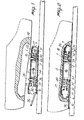
- a hidden type middle binding which comprises a box-type case, designated generally with the reference numeral 1, comprising a support plate 2 and a cover element 3 coupled thereto, defining the accommodation for the elements making up the binding.
- the plate 2 is provided, at its corners, with through-holes for accommodating screws 4 for fastening to the ski.
- the length dimension of the binding is extremely reduced thereby the binding itself does not affect the elastic and flexible characteristics of the ski.
- a forward ferrule 7 and a rear ferrule 6 Supported inside the box-type case 1 for sliding movement are a forward ferrule 7 and a rear ferrule 6 which may engage in corresponding hook-on seats defined in a recess provided in the sole of the ski boot, generally designated with the reference numeral 10.
- the binding further comprises means for adjusting the release tension which, in the embodiment described in Figures 1 to 4, includes substantially a pair of juxtaposed double wedges 11 engaging with a double-threaded bar 12 arranged crosswise to the longitudinal extent of the binding so as to create symmetrical translation of the double wedges 11 on rotating the threaded crossbar 12.
- the double wedges 11 act on actuating wedges 14 defining each a seat 15 for abutment respectively of a rear bias spring 17 and a forward bias spring 18 which act with an elastic thrust action against the ferrules 6 and 7 to hold them elastically in the extraction position.
- the ferrules 6 and 7 have a ledge element 20 which engages with a corresponding stop 21 defined by the cover element so as to prevent their slipping off the box-type case.
- Adjustment of the double wedges 11 causes translation in the longitudinal direction of the actuating wedges 14 with consequent different compressive action exerted on the springs 17 and 18 and thus change in the action of elastic bias exerted on the ferrules, which elastic bias action corresponds in practice to the release tension.
- An important feature of the invention is the provision of means for removably locking the ferrules 6 and 7 in a retracted position, thereby it is extremely easy to insert them into the recess defined in the sole 10, having then a successive automatic withdrawal of the ferrules to move into the locked position.
- Said removably locking means comprises in this specific case a pair of hooks 30 provided on lugs 31 extending from the ferrules 6 and 7 inwardly and engaging with the hook-on section of a pawl element 32 swingable mounted on the plate 2 and having the end 33 remote from the hook-on section acting against a thrust spring 34.
- the removably locking means further comprises actuators consisting of stems 40 acting on the end 33 and emerging upwardly from the box-type case 1.
- the stems 40 may be depressed by the sole to obtain release of the hook 30 from the pawl element 32 with consequent elastic exiting of the ferrules 6 and 7 and their engagement in the seats defined in the recess provided in the sole 10.
- the skier when he wants to hook on the boot or shoe, having previously positioned the ferrules 6 and 7 in the retracted position, is simply to bring the sole over the binding introducing the box-type case 1 into the recess provided in the sole itself and then by exerting a pressure action he pushes the actuators 40 which carry out automatic locking of the binding to the sole as a consequence of the disengagement of the removable locking means.
- a ski stop which comprises an oscillating lever 50 journalled in small ears 51 defined by the box-type case 1 and having a rear portion pressable from the sole to bring the lever 50 in a horizontal position and a forward introduction portion 53 which tends to penetrate the snow, when the rear portion is not depressed.
- the embodiment shown in Figure 6 has a pair of small lower connecting rods 60 journalled together and connected to the lower portion of the box-type case 1 at one end thereof and articulated, at the other end thereof, to a pair of small upper connecting rods 61.
- tension springs 62 are connected to the inner upper portion of the cover element 3 of the box-type case 1 and act on the upper connecting rods 61, whereas an actuator consisting of a pushbutton 63 acts at the mutual hinge connection between the small connecting rods 61.
- the connecting rods 60 and 61 practically encircle a tang portion 64 extending inwardly from the ferrules and defining teeth 65 which delimit a locking groove 66.
- Fig. 7 Similar in conception is the embodiment shown in Fig. 7 where there are provided lower jaw elements 70, journalled together and connected at the mutual pivot point to the plate 2 of the box-type case 1; thrust springs 71 provided between the upper free ends of the jaws 70 and the plate 2 act on the lower faces of these ends whilst actuators comprising small pegs 72 protruding from the cover portion of the case act on the upper face thereof.
- the thurst springs 71 can keep the jaw elements 70 within the groove 66 thus effecting locking by engagement with the teeth 65.
- a pressure action exerted on the small pegs 72 causes spreading of the jaws 70 with consequent disengagement thereof from the groove 66 and outward movement of the ferrules as urged by their thrust springs 17 and 18.
- FIG. 8 an embodiment is diagrammatically shown wherein it is possible to effect adjustment of the forward ferrule, again indicated at 7, and the rear ferrule, again indicated at 6, independently.
- the ferrules are provided with a removable locking means of the type previously described and not shown in Fig.8.
- the means of adjusting the release tension comprises a forward stem 81 and a rear stem 80 which are accessible from central channels 82 and 83 respectively defined by the ferrules 6 and 7.
- the stems 80 and 81 have a widened portion 84 and 85, respectively, which is rotatably accommodated in a middle block 86.
- the middle stems have each threaded portion 87 and 88, respectively, engaging washers 89 and 90 which are prevented from turning through a guide, for example, defined by the box-type case 1.
- the washer 89 or the washer 90 are caused to translate independently to each other with consequent change in the adjustment of the forward spring 17 or of the rear spring 18, and possibility of independently effecting adjustment of the release tension of the forward and rear ferrules.
- This embodiment in addition to affording an adjustment system for the hook-up or release tension obtained independently for the forward and rear ferrules, also affords containment of the binding transverse dimensions.
- the binding housing seat to be made in the sole of the boot affords improved continuity of the sole structure, ensuring the required rigidity for obtaining a good binding.
- the binding according to the invention achieves the objects set forth and in particular that it has an extremely compact conformation with considerable advantages both constructional and practical in nature, because it requires no particular actions or efforts to carry out the coupling between the binding and the sole.
- the materials used may be any ones depending on necessity.
Landscapes
- Footwear And Its Accessory, Manufacturing Method And Apparatuses (AREA)
Priority Applications (1)
| Application Number | Priority Date | Filing Date | Title |
|---|---|---|---|
| AT86111900T ATE53771T1 (de) | 1985-09-04 | 1986-08-28 | Mittlere bindung, insbesondere fuer skistiefel. |
Applications Claiming Priority (2)
| Application Number | Priority Date | Filing Date | Title |
|---|---|---|---|
| IT22065/85A IT1185691B (it) | 1985-09-04 | 1985-09-04 | Attacco centrale a scomparsa particolarmente per scarpe da sci |
| IT2206585 | 1985-09-04 |
Publications (3)
| Publication Number | Publication Date |
|---|---|
| EP0214558A2 true EP0214558A2 (de) | 1987-03-18 |
| EP0214558A3 EP0214558A3 (en) | 1987-09-02 |
| EP0214558B1 EP0214558B1 (de) | 1990-05-02 |
Family
ID=11190948
Family Applications (1)
| Application Number | Title | Priority Date | Filing Date |
|---|---|---|---|
| EP86111900A Expired - Lifetime EP0214558B1 (de) | 1985-09-04 | 1986-08-28 | Mittlere Bindung, insbesondere für Skistiefel |
Country Status (6)
| Country | Link |
|---|---|
| US (1) | US4923207A (de) |
| EP (1) | EP0214558B1 (de) |
| JP (1) | JPS6260503A (de) |
| AT (1) | ATE53771T1 (de) |
| DE (1) | DE3670774D1 (de) |
| IT (1) | IT1185691B (de) |
Cited By (1)
| Publication number | Priority date | Publication date | Assignee | Title |
|---|---|---|---|---|
| US6270090B1 (en) * | 1997-05-06 | 2001-08-07 | Skis Rossignol S.A. | Roller skate with removable boot |
Families Citing this family (11)
| Publication number | Priority date | Publication date | Assignee | Title |
|---|---|---|---|---|
| JPH01183515A (ja) * | 1987-12-30 | 1989-07-21 | Japan Exlan Co Ltd | 吸水性高強度繊維 |
| FR2705248B1 (fr) | 1993-05-14 | 1995-07-28 | Salomon Sa | Dispositif de retenue d'une chaussure sur une planche de glisse. |
| US5971420A (en) * | 1994-06-06 | 1999-10-26 | Shimano, Inc. | Snowboard binding |
| JP2003526487A (ja) * | 2000-03-16 | 2003-09-09 | レナート ペー リューデ スポーツ グッズ アクチエンゲゼルシャフト | スポーツ器具をブーツに接続するための装置 |
| AT410176B (de) * | 2000-07-21 | 2003-02-25 | Steinbach Christian | Bindungskonstruktion |
| US7267357B2 (en) | 2001-02-15 | 2007-09-11 | Miller Sports International, Inc. | Multi-function binding system |
| US7178821B2 (en) * | 2002-02-15 | 2007-02-20 | Miller Sports International, Inc. | Universal ski and snowboard binding |
| US8336903B2 (en) * | 2001-02-15 | 2012-12-25 | Miller Sport International, Llc | Multi-function binding system |
| AT413180B (de) * | 2002-06-26 | 2005-12-15 | Atomic Austria Gmbh | Schi- oder snowboardschuh mit einer ausnehmung im sohlenbereich |
| DE102013009762A1 (de) * | 2013-06-10 | 2014-12-11 | Andreas Allmann | Sicherheitsskibindungssystem |
| KR101620146B1 (ko) * | 2013-12-13 | 2016-05-12 | 현대자동차주식회사 | 로봇발의 원터치 착탈장치 |
Family Cites Families (13)
| Publication number | Priority date | Publication date | Assignee | Title |
|---|---|---|---|---|
| DE211411C (de) * | ||||
| US3061325A (en) * | 1961-05-08 | 1962-10-30 | Henry P Glass | Concealed ski attachment employing reciprocating locking members |
| DE1801192A1 (de) * | 1968-10-04 | 1970-04-23 | Voelkl Ohg Franz | Skistiefel mit eingebauter Skibindung vorzugsweise Sicherheitsskibindung |
| GB1312060A (en) * | 1969-05-28 | 1973-04-04 | Cristofanelli P | Detachable coupling attachment for skis |
| US3727932A (en) * | 1970-03-30 | 1973-04-17 | Chimera Res And Dev Inc | Ski binding |
| US3869136A (en) * | 1972-11-28 | 1975-03-04 | Richard S Jackson | Ski release binding |
| AT325485B (de) * | 1973-06-07 | 1975-10-27 | Smolka & Co Wiener Metall | Auslöseskibindung |
| AT323029B (de) * | 1973-06-29 | 1975-06-25 | Wiener Metalllwarenfabrik Smol | Skibindung |
| CH604775A5 (de) * | 1974-03-15 | 1978-09-15 | Salomon & Fils F | |
| FR2295768A1 (fr) * | 1974-12-23 | 1976-07-23 | Mitchell Sa | Ensemble pour la pratique du ski, compose d'une chaussure et d'une plaque sous-pied |
| FR2332773A1 (fr) * | 1975-11-26 | 1977-06-24 | Salomon & Fils F | Fixation de securite pour chaussure de ski a rechaussage automatique |
| US4063752A (en) * | 1976-04-16 | 1977-12-20 | Whitaker Richard A | Ski binding having present means and detent trigger for said present means |
| FR2533448A1 (fr) * | 1982-09-24 | 1984-03-30 | Delery Marc | Ensemble chaussure de ski a fixation integree multidirectionnelle |
-
1985
- 1985-09-04 IT IT22065/85A patent/IT1185691B/it active
-
1986
- 1986-08-28 AT AT86111900T patent/ATE53771T1/de not_active IP Right Cessation
- 1986-08-28 EP EP86111900A patent/EP0214558B1/de not_active Expired - Lifetime
- 1986-08-28 DE DE8686111900T patent/DE3670774D1/de not_active Expired - Fee Related
- 1986-09-04 JP JP61208843A patent/JPS6260503A/ja active Pending
-
1988
- 1988-01-27 US US07/148,198 patent/US4923207A/en not_active Expired - Fee Related
Cited By (1)
| Publication number | Priority date | Publication date | Assignee | Title |
|---|---|---|---|---|
| US6270090B1 (en) * | 1997-05-06 | 2001-08-07 | Skis Rossignol S.A. | Roller skate with removable boot |
Also Published As
| Publication number | Publication date |
|---|---|
| DE3670774D1 (de) | 1990-06-07 |
| EP0214558A3 (en) | 1987-09-02 |
| EP0214558B1 (de) | 1990-05-02 |
| US4923207A (en) | 1990-05-08 |
| IT1185691B (it) | 1987-11-12 |
| IT8522065A0 (it) | 1985-09-04 |
| ATE53771T1 (de) | 1990-06-15 |
| JPS6260503A (ja) | 1987-03-17 |
Similar Documents
| Publication | Publication Date | Title |
|---|---|---|
| EP0214558B1 (de) | Mittlere Bindung, insbesondere für Skistiefel | |
| US6116634A (en) | Fastener for a snow board | |
| US3061325A (en) | Concealed ski attachment employing reciprocating locking members | |
| US5944337A (en) | Automatic binding device | |
| EP0163054B1 (de) | Kombination von Skibindung und Skischuh | |
| US5383258A (en) | Ski-boot fastening with a device for adjusting the fastening tension | |
| EP0237633A2 (de) | Verschlussvorrichtung für die Schaftoberteile bei Skistiefeln | |
| EP0161441B1 (de) | Ratschenverschlussvorrichtung zur Kupplung mit einem Hebelverschluss-Zahnriemen, insbesondere für Ski-Schuh | |
| EP0071055B1 (de) | Schuh, insbesondere Skischuh, mit Vorrichtung zum Einstellen der Biegung und der Seiten- und Vorwärtsneigung | |
| US3950001A (en) | Adjusting mechanism for ski bindings | |
| US4765069A (en) | Device for closing quarters, particularly for ski boots | |
| US4893419A (en) | Rear-fitting shell-type ski boot | |
| US4694592A (en) | Closure device particularly for rear entrance ski boots | |
| US4182524A (en) | Safety ski binding | |
| US4319767A (en) | Heel binding for cross-country skis | |
| US4632419A (en) | Ski binding | |
| US4748751A (en) | Ski boot with a foot securing device | |
| US4155179A (en) | Ski boot | |
| US4767127A (en) | Roller skate with a binding strap fitting from the rear | |
| US20010010422A1 (en) | Assembly for retaining a boot on an apparatus for gliding or walking on snow or ice | |
| US4098010A (en) | Ski-boot | |
| EP0234317B1 (de) | Schliessvorrichtung, insbesondere für Schischuhe | |
| US4135734A (en) | Ski binding | |
| JPS5852666B2 (ja) | クロスカントリ用スキ−バインデイング | |
| US3672694A (en) | Means and techniques for releasably securing ski boots to skis |
Legal Events
| Date | Code | Title | Description |
|---|---|---|---|
| PUAI | Public reference made under article 153(3) epc to a published international application that has entered the european phase |
Free format text: ORIGINAL CODE: 0009012 |
|
| AK | Designated contracting states |
Kind code of ref document: A2 Designated state(s): AT CH DE FR LI |
|
| PUAL | Search report despatched |
Free format text: ORIGINAL CODE: 0009013 |
|
| AK | Designated contracting states |
Kind code of ref document: A3 Designated state(s): AT CH DE FR LI |
|
| 17P | Request for examination filed |
Effective date: 19880229 |
|
| 17Q | First examination report despatched |
Effective date: 19890412 |
|
| GRAA | (expected) grant |
Free format text: ORIGINAL CODE: 0009210 |
|
| AK | Designated contracting states |
Kind code of ref document: B1 Designated state(s): AT CH DE FR LI |
|
| REF | Corresponds to: |
Ref document number: 53771 Country of ref document: AT Date of ref document: 19900615 Kind code of ref document: T |
|
| REF | Corresponds to: |
Ref document number: 3670774 Country of ref document: DE Date of ref document: 19900607 |
|
| ET | Fr: translation filed | ||
| REG | Reference to a national code |
Ref country code: FR Ref legal event code: TP Ref country code: FR Ref legal event code: CD Ref country code: FR Ref legal event code: CA |
|
| PLBE | No opposition filed within time limit |
Free format text: ORIGINAL CODE: 0009261 |
|
| STAA | Information on the status of an ep patent application or granted ep patent |
Free format text: STATUS: NO OPPOSITION FILED WITHIN TIME LIMIT |
|
| 26N | No opposition filed | ||
| PGFP | Annual fee paid to national office [announced via postgrant information from national office to epo] |
Ref country code: FR Payment date: 19930818 Year of fee payment: 8 |
|
| PGFP | Annual fee paid to national office [announced via postgrant information from national office to epo] |
Ref country code: AT Payment date: 19930826 Year of fee payment: 8 |
|
| PGFP | Annual fee paid to national office [announced via postgrant information from national office to epo] |
Ref country code: CH Payment date: 19930830 Year of fee payment: 8 |
|
| PGFP | Annual fee paid to national office [announced via postgrant information from national office to epo] |
Ref country code: DE Payment date: 19931020 Year of fee payment: 8 |
|
| PG25 | Lapsed in a contracting state [announced via postgrant information from national office to epo] |
Ref country code: AT Effective date: 19940828 |
|
| PG25 | Lapsed in a contracting state [announced via postgrant information from national office to epo] |
Ref country code: LI Effective date: 19940831 Ref country code: CH Effective date: 19940831 |
|
| PG25 | Lapsed in a contracting state [announced via postgrant information from national office to epo] |
Ref country code: FR Effective date: 19950428 |
|
| REG | Reference to a national code |
Ref country code: CH Ref legal event code: PL |
|
| PG25 | Lapsed in a contracting state [announced via postgrant information from national office to epo] |
Ref country code: DE Effective date: 19950503 |
|
| REG | Reference to a national code |
Ref country code: FR Ref legal event code: ST |