EP0214623A2 - Fixation de vis de serrage aux boulons de jante - Google Patents
Fixation de vis de serrage aux boulons de jante Download PDFInfo
- Publication number
- EP0214623A2 EP0214623A2 EP86112282A EP86112282A EP0214623A2 EP 0214623 A2 EP0214623 A2 EP 0214623A2 EP 86112282 A EP86112282 A EP 86112282A EP 86112282 A EP86112282 A EP 86112282A EP 0214623 A2 EP0214623 A2 EP 0214623A2
- Authority
- EP
- European Patent Office
- Prior art keywords
- adapter
- inner part
- skid device
- hub
- elongated holes
- Prior art date
- Legal status (The legal status is an assumption and is not a legal conclusion. Google has not performed a legal analysis and makes no representation as to the accuracy of the status listed.)
- Granted
Links
Images




Classifications
-
- B—PERFORMING OPERATIONS; TRANSPORTING
- B60—VEHICLES IN GENERAL
- B60C—VEHICLE TYRES; TYRE INFLATION; TYRE CHANGING; CONNECTING VALVES TO INFLATABLE ELASTIC BODIES IN GENERAL; DEVICES OR ARRANGEMENTS RELATED TO TYRES
- B60C27/00—Non-skid devices temporarily attachable to resilient tyres or resiliently-tyred wheels
- B60C27/06—Non-skid devices temporarily attachable to resilient tyres or resiliently-tyred wheels extending over the complete circumference of the tread, e.g. made of chains or cables
- B60C27/14—Non-skid devices temporarily attachable to resilient tyres or resiliently-tyred wheels extending over the complete circumference of the tread, e.g. made of chains or cables automatically attachable
-
- B—PERFORMING OPERATIONS; TRANSPORTING
- B60—VEHICLES IN GENERAL
- B60C—VEHICLE TYRES; TYRE INFLATION; TYRE CHANGING; CONNECTING VALVES TO INFLATABLE ELASTIC BODIES IN GENERAL; DEVICES OR ARRANGEMENTS RELATED TO TYRES
- B60C27/00—Non-skid devices temporarily attachable to resilient tyres or resiliently-tyred wheels
- B60C27/02—Non-skid devices temporarily attachable to resilient tyres or resiliently-tyred wheels extending over restricted arcuate part of tread
- B60C27/04—Non-skid devices temporarily attachable to resilient tyres or resiliently-tyred wheels extending over restricted arcuate part of tread the ground-engaging part being rigid
-
- B—PERFORMING OPERATIONS; TRANSPORTING
- B60—VEHICLES IN GENERAL
- B60C—VEHICLE TYRES; TYRE INFLATION; TYRE CHANGING; CONNECTING VALVES TO INFLATABLE ELASTIC BODIES IN GENERAL; DEVICES OR ARRANGEMENTS RELATED TO TYRES
- B60C27/00—Non-skid devices temporarily attachable to resilient tyres or resiliently-tyred wheels
- B60C27/20—Non-skid devices temporarily attachable to resilient tyres or resiliently-tyred wheels having ground-engaging plate-like elements
-
- F—MECHANICAL ENGINEERING; LIGHTING; HEATING; WEAPONS; BLASTING
- F16—ENGINEERING ELEMENTS AND UNITS; GENERAL MEASURES FOR PRODUCING AND MAINTAINING EFFECTIVE FUNCTIONING OF MACHINES OR INSTALLATIONS; THERMAL INSULATION IN GENERAL
- F16B—DEVICES FOR FASTENING OR SECURING CONSTRUCTIONAL ELEMENTS OR MACHINE PARTS TOGETHER, e.g. NAILS, BOLTS, CIRCLIPS, CLAMPS, CLIPS OR WEDGES; JOINTS OR JOINTING
- F16B33/00—Features common to bolt and nut
-
- F—MECHANICAL ENGINEERING; LIGHTING; HEATING; WEAPONS; BLASTING
- F16—ENGINEERING ELEMENTS AND UNITS; GENERAL MEASURES FOR PRODUCING AND MAINTAINING EFFECTIVE FUNCTIONING OF MACHINES OR INSTALLATIONS; THERMAL INSULATION IN GENERAL
- F16B—DEVICES FOR FASTENING OR SECURING CONSTRUCTIONAL ELEMENTS OR MACHINE PARTS TOGETHER, e.g. NAILS, BOLTS, CIRCLIPS, CLAMPS, CLIPS OR WEDGES; JOINTS OR JOINTING
- F16B37/00—Nuts or like thread-engaging members
- F16B37/04—Devices for fastening nuts to surfaces, e.g. sheets, plates
-
- F—MECHANICAL ENGINEERING; LIGHTING; HEATING; WEAPONS; BLASTING
- F16—ENGINEERING ELEMENTS AND UNITS; GENERAL MEASURES FOR PRODUCING AND MAINTAINING EFFECTIVE FUNCTIONING OF MACHINES OR INSTALLATIONS; THERMAL INSULATION IN GENERAL
- F16B—DEVICES FOR FASTENING OR SECURING CONSTRUCTIONAL ELEMENTS OR MACHINE PARTS TOGETHER, e.g. NAILS, BOLTS, CIRCLIPS, CLAMPS, CLIPS OR WEDGES; JOINTS OR JOINTING
- F16B37/00—Nuts or like thread-engaging members
- F16B37/14—Cap nuts; Nut caps or bolt caps
-
- Y—GENERAL TAGGING OF NEW TECHNOLOGICAL DEVELOPMENTS; GENERAL TAGGING OF CROSS-SECTIONAL TECHNOLOGIES SPANNING OVER SEVERAL SECTIONS OF THE IPC; TECHNICAL SUBJECTS COVERED BY FORMER USPC CROSS-REFERENCE ART COLLECTIONS [XRACs] AND DIGESTS
- Y10—TECHNICAL SUBJECTS COVERED BY FORMER USPC
- Y10T—TECHNICAL SUBJECTS COVERED BY FORMER US CLASSIFICATION
- Y10T403/00—Joints and connections
- Y10T403/51—Joints and connections including spaced, diverse connections
Definitions
- the invention relates to an anti-skid device, in particular for pneumatic tires vehicle wheels on ice and snow surfaces, the like from a hub attachable to the wheel disc or rim, with openings for attachment to the rim bolts, wheel bolts. is provided, and a on the hub by means of a retaining ring and lockable support plate with a number of equally spaced radial anti-skid arms made of a pre-bent, the tire tread and outside and inside at its free ends carrying a gripping profile made of a plastic or a other suitable material, with spikes or metal bodies on the outside, and an adapter for screw heads and the like.
- Snow chains are not very popular because they are often difficult to put on the vehicle tires and they have to be driven in such a way that the road is not damaged, i.e. that the snow chains have to be removed from dry road sections following snow or ice covered road sections, especially since the snow chains when driving are subject to high wear on dry roads and, moreover, do not allow high speeds.
- Snow chains and traction tires are often not available, for example, in the case of ice surfaces caused by drizzle falling on frozen road surfaces.
- the studded tires are also not always applicable.
- starting aids In addition to snow chains and traction tires, starting aids are known, but they do not replace snow chains and traction tires. These traction aids, which consist of clamps attached to the tires, only serve to drive a vehicle a short distance out of morass or snow.
- a non-skid device in particular for pneumatic tires on ice and snow surfaces, consisting of a hub attachable to the wheel disc or rim, or the like with openings for attachment to the rim bolts, wheel bolts. is provided, and a support disk held and lockable on the fastening disk by means of a retaining ring with a number of anti-skid arms, which run radially at the same distance from one another, from a pre-bent profile made of a plastic or a bearing profile that supports the tire tread and on the outside and inside at its free ends other suitable material and with externally attached spikes or metal bodies, is known from DE-GM 83 27 385.
- This known anti-skid device has a hub which can be connected to the wheel disk or rim and which is provided with lockable brackets for the mounting disk, the hub also remaining connected to the wheel disk or rim when the anti-skid device is not required.
- the support disk itself has a central opening, while the circular hub has a circular receptacle in the center and a smaller diameter than the diameter of the hub part carries, which at a distance from the hub adjacent to its upper edge on its circumference has a number of bead-like projections with underneath them formed, tapering from insertion openings, in the circumferential direction of the receiving part slideways and guideways and which includes the support disk surrounding the receiving part carries the anti-skid arms, which is secured by means of a securing ring placed on the receiving part, which can be inserted into the slideways and guideways on the receiving part, effecting a bayonet-like locking bars with conically tapering sections extending towards the insertion openings and at least one on its inner wall surface has leaf spring-like catch
- the hub with the specially designed receiving part always remains on the wheel disk or rim, while for the operating state of the anti-skid device, the support disk with the anti-skid arms is placed on the hub and locked there by means of the securing ring.
- the hub is provided with openings for fastening to the rim bolts, wheel bolts or the like. Mistake.
- the hub has a predetermined number of openings for fastening to the rim bolts, wheel bolts or the like. on.
- the hub of the fastening disk is not a multitude of different ones can have mutually arranged openings for receiving the rim bolts or wheel bolts in order to also be able to fasten the hub to wheel disks or rims, in which other dimensions and assignments are given for the rim bolts or wheel bolts.
- the hub is attached to the wheel disks or rims using rim bolts or wheel bolts.
- the invention solves the problem of designing an anti-skid device of the type mentioned at the outset in such a way that it can be used in a large number of vehicles without great technical outlay, even if their wheel disks or rims have different bolt circles and pitches for the rim bolts or wheel bolts, so that there is no need to stock a large number of differently designed hubs for the individual wheel disc or rim types. Furthermore, it is an object of the invention to provide an adapter which can be pushed over rim screw heads, heads of screws of all kinds and nuts, especially since there are only a few wrench sizes, this adapter being intended to bridge relatively large tolerances of the wrench sizes and to ensure a secure fit; it should be easy to attach and if possible no special tools should be required. In addition, it should be easy to remove and often reusable.
- the hub with an integrally formed receiving part carries an adapter disk on its side facing away from the supporting disk, which is connected to the hub by means of screw connections and which has a number of radially extending elongated holes in the same and / or has unequal or more divisions.
- the adapter disk has at least two elongated holes lying around the center of the adapter disk with different diameters, the elongated holes on the circular line adjacent to the center of the adapter disk being able to have the same distances, while the elongated holes on the outer circular line are the same and unequal distances from each other.
- the adapter disk has four elongated holes on the circular line adjacent to the center; however, six elongated holes can also be provided on the outer circular line.
- six elongated holes can also be provided on the outer circular line.
- three elongated holes are formed on the outer circular line at the same distance from one another in the adapter disk, the distance between two of these elongated holes being approximately 120 ° and the first of the three elongated holes at a distance of approximately 75 ° from that through the center of the adapter disc extending center line, while of the other three elongated holes, the first elongated hole is at a distance of approximately 45 ° from the center line and the other two elongated holes counterclockwise circumferentially at a distance from one another in the adapter disc are arranged, which is approximately 90 °, the first and last elongated holes being opposite each other.
- five radially extending elongated holes arranged at an equal distance from one another are formed in the adapter disk on a circular line facing the center of the adapter disk, and five radially extending elongated holes are arranged on an outer circular line at an equal distance from one another, which are eccentric to the elongated holes and offset to these are arranged on the circular line.
- the first slot of the five slots in the adapter disk is arranged at a distance of about 24 ° from the center line through the center of the adapter disk, while the first slot adjacent to the slot of the slots located on the outer circular line is at a distance from the center line of about 47 ° lying in the adapter plate.
- the elongated holes lying on the outer circular line are half the length of the elongated holes lying on the inner circular line.
- the adapter disk has four or five equally spaced and threaded hub mounting screw receiving through holes.
- the advantage of using an adapter disk on the hub is that only a few hub designs are required.
- the adapter disk has threaded bores in the hub which match the fastening screw through-bores and, moreover, a number of elongated holes which are formed in the same or more divisions in a radial, ie radial, manner in the adapter disk, so that, owing to the large number of holes provided in the adapter disk Elongated holes, the fastening hub can be fastened to each wheel disk or rim by means of the adapter disk, since the large number of differently arranged elongated holes offers the possibility of adapting to the threaded holes for the rim bolts or wheel bolts, which are provided differently in the wheel disks or rims.
- pitches being the known pitches, such as 3, 4, 5, 6, 8, 10, 11 - and divisions of 12.
- the invention relates to an anti-skid device, in particular for pneumatic tires vehicle wheels on ice and snow surfaces, the like from a hub attachable to the wheel disc or rim, with openings for attachment to the rim bolts, wheel bolts. is provided, and a lockable on the hub by means of a retaining ring and lockable with a number of anti-skid arms running radially at the same distance from each other, consisting of a pre-bent profile that crosses the tire tread and has a gripping profile on the outside and inside at its free ends, made of a plastic or another suitable material with spikes or metal bodies on the outside, one head, such as hexagon head or the like, for example a wheel bolt, bolt, nut or the like.
- encompassing adapter which consists of a cap-like outer part and a cap-like inner part overlapped by the outer part with fixed and / or loose form grippers, which are formed by longitudinal slots in the inner part wall in the form of collet-like sections or as individual moldings, with screwing or pressing into one another of the outer part over the inner part in the longitudinal direction of the screw, the form gripper against the bolt, nut or the like., the screw head and the like.
- connection being releasable and reusable, and that foreign parts such as the hub of the anti-skid device with the bolts, nuts, Screw heads and the like can be connected by means of a threaded hole with screws.
- a configuration is particularly advantageous according to which the outer part of the adapter, adjacent to its lower peripheral edge on the inside wall side, has a wall section which tapers conically towards the edge and the inner part adjacent to its lower peripheral edge on the outside wall side has a wall section which widens conically towards the edge, in which State of connection of the outer part with the inner part of the outer part cone is pressing against the inner part cone.
- the outer part can be adjacent to its lower peripheral edge on the inside wall side toward the edge have a conically widening wall section and the inner part adjacent to its lower circumferential edge on the outer wall side have a wall section which tapers conically towards the edge, the outer part cone pulling against the inner part cone when the outer part is connected to the inner part.
- the outer part of the adapter has in its lower region on the inside wall side a wall section which widens conically towards the edge, this outer part cone and a conical wall section on the inner part being pressed against provided double cones of the loose mold grippers.
- the invention furthermore relates to an adapter for bolts, nuts, heads of screws, such as wheel bolts, for example for fastening the hub of an anti-skid device, in particular for pneumatic tires for vehicle wheels on ice and snow surfaces, which consist of a hub which can be fastened to the wheel disk or rim with openings for fastening to the rim bolts, wheel bolts or the like.
- a on the hub by means of a retaining ring and lockable support plate with a number of equally spaced radial anti-skid arms made of a pre-bent, the tire tread and outside and inside at its free ends carrying a gripping profile made of a plastic or a other suitable material with spikes or metal bodies on the outside, the head, such as a hexagon head or the like. the rim bolt or the like.
- adapter consists of a cap-like outer part and a cap-like inner part overlapped by the outer part with fixed and / or loose form grippers, the inner part wall of the inner part having longitudinal slots for forming collet-like sections as a form gripper or are formed as individual moldings, wherein by screwing or pushing the outer part over the inner part in the longitudinal direction of the screw, the mold gripper against the bolt, nut or the like, the screw head and the like.
- connection to form a permanent, secure connection between the adapter and the bolts, nuts or the screw head, the connection being releasable and reusable, and with foreign parts such as the hub of the anti-skid device with the bolts, nuts, Screw heads and the like can be connected by means of a threaded hole with screws.
- collet-like adapter that consists of two components: an inner part that has a threaded hole at one end and an external thread. At the other end it has a collet-like hexagon socket, which is slotted and is round on the outside with a molded cone. Furthermore, the outer part, which has at one end a threaded bore that matches the external thread of the inner part and an external hexagon with the same width across flats of the internal hexagon of the inner part. At the other end, the outer part has a counter cone to the inner part.
- the collet-like hexagon socket When the outer part is screwed onto the inner part, the collet-like hexagon socket is pressed together by the two cones and the adapter, when it is pushed over a hexagon nut or over a hexagon head of a screw, is securely and securely connected to it. The connection is released by screwing the outer part back.
- the threaded hole in the inner part is used to attach all possible parts, such as the hub of the anti-skid device, to the adapter using a screw. Since the end of the inner part with the threaded hole protrudes over the outer part, the distance to the nut or screw is determined by a key wide tolerances not changed. Since there are only a few wrench sizes, only a few adapter types are necessary for all car types and brands and must be kept in stock.
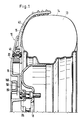
- the anti-skid device 10 consists of a provided with a central opening, i.e. ring-shaped support disk 20 to which a number of radially extending anti-skid arms 40 are fastened, which are arranged at the same distance from one another and can be pivoted in a small area about axes 41 running parallel to the wheel disk bearing axis. This pivotability of the anti-skid arms in a small area enables the anti-skid device to be attached when the vehicle is stationary.
- the anti-skid arms 40 all set up at the same distance from one another, even if the anti-skid arms come to lie to the side of the tire support surface during assembly in the area of the tire support surface on a surface such as a road or the like.
- the anti-skid device is attached to the wheel provided with a tire 13, which also represents the rim.
- the wheel 11 is provided with a brake part, not shown in the drawing.
- the tread area of the tire 13 is 14 and the outside surface of the tire designated 15 (Fig. 1).
- Each anti-skid arm 40 is fastened to the support disk 20 by means of bolt-like or rivet-like connecting means, and detachable attachment of the anti-skid arms 40 to the support disk 20 is also possible in order to be able to replace worn anti-skid arms 40.
- eight anti-skid arms 40 are provided on the support disk 20.
- the number of anti-skid arms can be chosen arbitrarily. However, there must be at least two anti-skid arms. All anti-skid arms are arranged at the same angular distance from each other.
- Each anti-skid arm 40 is made of resilient material, such as spring steel, so that an elastic bending of the free end portion of each anti-skid arm 40 is possible in the area of the tread 14 of the tire 13.
- the anti-skid arms 40 are pre-shaped such that after the anti-skid device 10 is attached to a vehicle wheel, the free ends of the anti-skid arms overlap the tire tread 14.
- spring steel other suitable materials can also be used for the production of the anti-skid arms 40.
- the anti-skid arms 40 can also consist of suitable plastics.
- the anti-slip arms 40 have gripping profiles on the outside, so that a high grip can be achieved. These gripping profiles can also be designed as spikes.
- the fastening device for the Gleitschutzvor device 10 on the rim 11 of a vehicle wheel consists of a hub 50 and a locking ring 150 (FIGS. 3 and 7).
- the hub 50 is provided with a number of openings 51 see that are used to attach to the rim bolts 18.
- the rim screws 18 for fastening the hub 50 can be provided with internally threaded bores for receiving locking screws 85, by means of which the hub 50 can be fastened to the wheel rim 11 via the rim screw and for fastening the hub 50 serve the adapter disc described below or on the wheel bolts or nuts.
- the circular, disk-shaped hub 50 has in the middle a receiving part 52 with a circular cross section, which is designed as a cylindrical shaped body and is an integral part of the hub 50.
- This receiving part 52 has a diameter that is smaller than the diameter of the hub 50.
- the receiving part 52 On its outer circumference, namely adjacent to the upper peripheral edge 53, the receiving part 52 has a number of bead-like projections 55 which are arranged at the same distance from one another. In the exemplary embodiment shown in FIG. 3, four bead-like projections 55 projecting laterally from the circumference of the receiving part 52 are provided on the receiving part 52 of the hub 50.
- a slideway and guideway 60 is formed below each bead-like extension 55.
- This slideway and guideway 60 is designed as a recess and has an insertion opening 56, from which the slideway and guideway 60 tapers conically toward the end region, so that the insertion opening 56 is larger than the end region 56a.
- the recess forming the slide and guideway 60 is then wedge-shaped and is delimited by an annular bead 57 in the area adjacent to the hub 50.
- the end region 56a of the slide and guideway 60 also has a limit in the form of a stop, which, however, need not necessarily be present.
- the annular bead 57 which is formed on the outer circumference of the receiving part 52, at the same time represents the upper limit for the support disk 20 placed on the receiving part 52 of the hub 50 (FIG. 3). In the area of the openings 51, this annular bead 57 is interrupted, since a section of each opening 51 is guided as a partial bore into the receiving part 52 (FIG. 3).
- All of the slideways and guideways 60 below the bead-like projections 55 are designed and arranged such that their insertion openings 56 face the respectively preceding end region 56a.
- Each bead-like extension 55 is advantageously provided with a flattened portion 55a in its upper region in order to make it easier to put on the securing ring 150.
- the receiving part 52 of the hub 50 serves for receiving the support disk 20 with the anti-skid arms 40 of the anti-skid device 10 and for receiving the locking ring 150.
- This retaining ring 150 with an outer diameter that is slightly smaller than the diameter of the hub 50 or is equal to the diameter of this hub, has 150a on its inner wall surface a number of locking webs 155, the number of which corresponds to the number of bead-like projections 55 or the number of slideways and guideways 60 on the receiving part 52 of the hub 50.
- This locking webs 155 are designed so that they can be inserted into the slideways and guideways 60 so that a bayonet-like locking between the fuse ring 150 and the receiving part 52 or the hub 50 takes place (Fig. 7).
- the locking webs 155 are then wedge-shaped, so that when the retaining ring 150 is placed on the hub 50, the conically tapered end portions of each locking web 155 of the insertion opening 56 of the recesses forming the slide and guide tracks 60 between the bead-like extension 55 and the annular bead 57 face , so that when the locking ring 150 is rotated about its vertical central axis in the direction of the arrow X, the locking webs 155 are inserted into the slideways and guideways 60 and thus the bayonet-type locking is achieved (FIGS. 6 and 7).
- the locking webs 155 In order to be able to place the locking ring 150 on the receiving part 52 of the hub 50 in such a way that the locking webs 155 of the locking ring 150 can be inserted into the slideways and guideways 60, the locking webs 155 have a length which corresponds to the distance between two bead-like projections 55 corresponds to the hub 50. In this way, the locking webs 155 in the mounting position of the locking ring 150 can be passed between two bead-like projections 55 until the locking ring 150 comes to rest on the ring bead 57 and the locking webs 155 can be inserted into the recesses forming the slideways and guideways 60.
- the locking ring 150 is provided with additional locking devices.
- These locking devices are designed as leaf spring-like catches 160, specifically in the form of resilient-elastic tongues, which in recesses 156 on the inner wall surface 150a of the locking ring 150 are arranged.
- the arrangement and design of these leaf spring-like catches 160 is such that when the retaining ring 150 is placed on the receiving part 52 of the hub 50, but still in the unlocked position, the leaf spring-like catches 160 move from the bead-like projections 55 on the receiving part 52 into their recesses 156 on the inner wall surface 150a of the locking ring 150 are pressed.
- the leaf spring-like catches come to rest in the region of recesses 152 which are formed on the circumference of the receiving part 52. Since the leaf spring-like catches 160 strive to automatically spring out of their recesses 156 in the direction of the arrow X1, the leaf spring-type catches 160 come to rest in the recesses 152 on the receiving part 52 and form the lock there in that the free ends of the leaf spring-like catches 160 come to rest on stops 153 which delimit the recesses 152 in the receiving part 52. The free ends of the leaf spring-like catches 160 engaging in these recesses with the stops 153 thus prevent the locking ring 150 from loosening against its direction of rotation for locking and being able to lift off the receiving part 52.
- the number of leaf spring-like catches 160 on the inner wall surface 150a of the locking ring 150 can be chosen as desired. In the exemplary embodiment shown in FIG. 7, two leaf spring-like catches 160 are provided, which are provided at the same distance from one another on the inner wall surface 150a of the securing ring 150. The number of recesses 152 in the circumference of the receiving part 52 of the hub 50 corresponds to the number of leaf spring-like catches 160.
- the leaf spring-like catches 160 are from Her position of the circlip 150 simultaneously molded.
- the locking ring 150 consists of plastics with a resilient-elastic behavior in the case of tongue-shaped configurations, as is the case with the leaf spring-like catches 160.
- leaf spring-like catches 160 instead of leaf spring-like catches 160, differently designed locking devices can also be used.
- locking devices there is the possibility of using radially displaceable and spring-loaded bolts which engage in corresponding recesses on the circumference of the receiving part 52 of the hub 50, but corresponding precautions must then be taken to effect an unlocking insofar as the locking bolts are in theirs Starting position must be withdrawn in order to be able to remove the locking ring 150 from the hub 50.
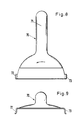
- the unlocking key 70 shown in FIGS. 8 and 9 is provided, which consists of a handle-like handle 71, which carries at its one free end two spaced-apart pressure tongues 72, 73, which are arranged approximately perpendicular to the handle-like handle 71 .
- the distance between these two pressure tongues 72, 73 corresponds to the distance between the leaf spring-like catches 160 lying opposite one another, so that the pressure tongues 72, 73 can be inserted into the two recesses 152 on the hub 50.
- the two recesses 152 on the receiving part 52 have additional recesses 75 into which the two pressure tongues 72, 73 of the unlocking key 70 can be inserted.
- the pressure tongues 72, 73 take the locking ring 150 with them and guide the locking webs 155 out of the slideways and guideways 60 with a further rotational movement the hub 50 until the locking webs 155 come to rest between the bead-like projections 55, so that in this position the locking ring 150 can then be removed from the receiving part 52.
- the locking ring 150 is also placed on the receiving part 52 by means of the unlocking key 70 in such a way that the pressure tongues 72, 73 of the unlocking key 70 are inserted into the recesses 75 and, when the unlocking key 70 is turned in the direction of the arrow X (FIG. 7) the pressure tongues 72, 73 also hold the locking ring 150 until the locking webs 155 come to rest in the slideways and guideways 60 and the bayonet lock is produced.
- the recesses 75 For taking the locking ring 150 through the pressure tongues 72, 73 of the unlocking key 70, the recesses 75 have stops 78 in the fastening area of the leaf spring-like catches 160 (FIG. 7).
- the hub 50 has spacer rings or spacer elements 80 on its wall surface 50a facing away from the receiving part 52 in the area of the rim bolt or wheel bolt openings, which are designed as exchangeable adapters. This makes it possible to adapt the fastening device to different tire sizes by means of spacer rings 80 of different sizes.
- an anti-skid device 10 consisting of the support plate 20 with the anti-skid arms 40, on the rim or the wheel 11 of a vehicle using the fastening device consisting of the hub 50 and the locking ring 150, is carried out in such a way that after fastening the hub 50 by means of the locking screws 18, which are screwed into the wheel bolts or nuts, on the wheel rim 11, the support disk of the anti-skid device 10 is placed on the receiving part 52 of the hub 50.
- the retaining ring 150 is then placed thereon, so that its locking webs 155 come to rest on the receiving part 52 in the spaces between the bead-like projections 55.
- the pressure tongues 72, 73 of the unlocking key 70 are inserted into the recesses 75 and the pivoting of the unlocking key 70 in the direction of the arrow X (FIG. 7), whereby the locking ring 150 is pivoted about its vertical central axis until the locking webs 155 on the inner wall surface 150a of the circlip 150 come to rest in the recesses forming the slide and guide tracks 60.
- the leaf spring-like catches 160 snap into the recesses 152 on the receiving part 52 in a self-resilient manner, as a result of which locking takes place against inadvertent loosening of the locking ring 150.
- the anti-skid device 10 is held on the rim 11 of the vehicle wheel by means of the fastening device comprising the hub 50 and the securing ring 150 such that the anti-skid arms 40 of the anti-skid device 10 overlap the tire tread.
- the anti-skid device 10 is removed with the aid of the unlocking key 70, which in turn is inserted into the recesses 75 with its pressure tongues 72, 73.
- the leaf spring-like catches 160 are moved from their locking position into their starting position in the recesses 156 on the inner wall surface 150a of the locking ring 150.
- the locking ring 150 is rotated until the locking webs 155 of the locking ring 150 are led out of the slideways and guideways 60 on the receiving part 52.
- the locking ring 150 can then be lifted off. There is then a removal of the support plate 20 of the anti-skid device 10 from the receiving part 52 of the hub 50. If the anti-skid device 10 is not used further, but with the fastening device ready, the securing ring 150 is simply placed and locked onto the hub 50, so that the It is possible to attach the anti-skid device 10 if this should become necessary.
- the support plate 20 of the anti-skid device 10 is provided with a central opening so that the support disk 20 can be placed on the receiving part 52 of the hub 50.
- the diameter of this central opening is larger than the diameter of the receiving part 52, so that the support disk 20 of the anti-skid device 10 held on the receiving part 52 can perform eccentric movements.
- the anti-skid arms 40 encompassing the tire tread in conjunction with the support disk 20 can adapt to the flexing movements of the rolling tire.
- the diameter of the central opening in the support plate 20 is dimensioned such that the support plate 20 can be guided over the annular bead 57 on the receiving part 52.
- the support disk 20 is secured at the top by means of the retaining ring 150 which overlaps the support disk in sections, while the securing to the rim is carried out by the hub 50 itself.
- the hub 50 has an adapter disk 300 on its side facing away from the supporting disk 20, which is connected by means of screw connections 350 to the receiving part 52 of the hub 50.
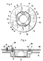
- the adapter disk 300 has a number of hub fastening screw receiving through-holes 340 lying on a circular line 341 around the center point M of the adapter disk 300, which are connected to the through-holes 51 (FIGS. 3 and 4 ) of the receiving part 52 of the hub 50 are aligned, the number of through holes 340 corresponding to the number of through holes 51 in the receiving part 52.
- These hub mounting screw receiving through holes 340 are equally spaced from each other. In the exemplary embodiment shown in FIGS. 3 and 10, four receiving through holes 340 are provided in the adapter disk 300, while in the further embodiment of the adapter disk 300 shown in FIG. 11, five receiving through holes 340 are provided on the circular line 341. The number of these through-bores 340 depends on the size of the hub 50 with its receiving part 52. The through-bores 340 are provided with an internal thread, so that after the corresponding screws have been inserted, the hub 50 placed on the adapter disk 300 can be detachably connected to the adapter disk 300 .
- the adapter disk 300 has a number of radially extending elongated holes 302,303,304,305 and 312,313,314,315,316,317, these elongated holes being formed in the adapter disk 300 in identical or more and also unequal divisions (FIG. 10)
- the elongated holes are arranged distributed over two circular lines with different diameters.
- the elongated holes 302 to 305 are arranged on the circular line 301 adjacent to the center point M of the adapter disk 300 at equal distances from one another, while the elongated holes 312 to 314 and 315 to 317 on the outer circular line 311 are partly arranged at uneven distances from one another.
- Four elongated holes are provided on the circular line 301 adjacent to the center point M of the adapter disk 300, while six elongated holes are located on the outer circular line 311.
- the further elongated holes 315, 316, 177 lying on the outer circular line 311 are arranged in the adapter disk 300 as follows: the first elongated hole 315 is arranged at a distance of approximately 45 ° from the center line ML.
- the elongated holes 316, 317 adjoin this in a counterclockwise direction, the distance of the elongated hole 315 from the elongated hole 316 and the distance of the elongated hole 316 from the elongated hole 317 being approximately 90 °, the two elongated holes 315, 317 being opposite one another.
- the division and arrangement of the elongated holes 302 to 305 and 312 to 314 and 315 to 317 in the adapter disk 300, which can be seen in FIG. 10, is then obtained.
- five radially extending elongated holes 322,323,324,325,326 are arranged at the same distance from one another on a circular line 321 facing the center point M of the adapter disk, while five further elongated holes 332,333,334,335,336 are formed in the adapter disk on an outer circular line 331. which are also radial and are arranged at the same distance from each other. However, these elongated holes 332 to 336 are offset by a section from the other elongated holes 322 to 326.
- the first of the elongated holes arranged on the inner circular line 321, the elongated hole 322, is arranged at a distance of approximately 24 ° from the center line ML placed through the adapter disk center point M. This is followed by the other elongated holes at equal distances from one another 323 to 326.
- the first elongated hole 332 of the elongated holes lying on the outer circular line 331 begins at a distance of approximately 47 ° from the center line ML, the other elongated holes 333 to 336 then adjoining one another at equal distances.
- the hub fastening screw receiving holes 340 on the circular line 341 are arranged in relation to the elongated holes 322 to 326 and 332 to 336 such that the first receiving hole 340 lies on the center line ML and then the respective subsequent receiving hole is at a distance of approximately 72 ° from the preceding receiving hole is arranged.
- the elongated holes 332 to 336 are dimensioned shorter than the elongated holes 322 to 326.
- the elongated holes 332 to 336 have approximately half the length of the elongated holes 322 to 326.
- all the elongated holes are of the same length.
- the arrangement of the elongated holes on their circular lines is such that the circular lines run through the centers of the respective elongated holes.
- the adapter disk 300 consists of metallic, in particular corrosion-resistant, materials, but other suitable materials, in particular those with high strength, can also be used to manufacture the adapter disk.
- the elongated holes in the adapter disk 300 are arranged in relation to the circular openings having threads so that the hub supports 50a (FIG. 4) or spacer elements 80 (FIG. 1) do not interfere with the fastening screws 86 in the elongated holes of the adapter disks.
- the adapter disk 300 can also have a large number of divisions.
- the wheel bolts or wheel nuts are not passed through the hub 50, but rather are behind the hub and are screwed to the hub or to the adapter disk 300 with the locking screws.
- the internal adhesion of the anti-skid arms to the tire tread is particularly advantageous due to profile bodies provided on the free ends of the anti-skid arms, which engage in the profile of the tire tread.
- the hub 50 of the anti-skid device In order to be able to attach the anti-skid device 10 to the rim 11 of a vehicle wheel, it is necessary for the hub 50 of the anti-skid device to be connected to the rim. This is done by means of rim screws, which, however, must have a special configuration in order to be able to accommodate the actual locking screws 85 for the hub 50. For this reason, it is necessary to use rim bolts which have a special configuration in order to be able to fasten the hub 50. For this purpose, specially designed rim bolts are mostly used and because of the large number of motor vehicle types, it is also necessary that a large number of wheel rim bolts are then available and kept in stock in order to be able to use the anti-skid device for the various motor vehicle models.
- an adapter 400 As shown in FIGS. 12 to 21, it is possible to use existing rim bolts and to be able to fasten the locking screws, which serve to secure the hub 50, by means of the adapter.
- This adapter 400 in its various embodiments is designed such that the adapter placed on the screw head of a rim screw establishes the connection between the rim screw and the locking screw 85 for the hub. Since the adapter 400 can be used for the various rim bolts, bolts or nuts, it is not necessary Manufacture a large number of adapters and keep them in stock, but it is sufficient if, for example, three adapter sizes are available. Surprisingly, all rim bolts of known motor vehicle models can be operated with these three adapter sizes.
- the adapter 400 engages or engages over the head 435, such as a hexagon head or the like, a rim bolt 434 or a nut or the head of a wheel bolt.
- the head 435 such as a hexagon head or the like, a rim bolt 434 or a nut or the head of a wheel bolt.
- the adapter 400 consists of a cap-shaped outer part 401 and a cap-like inner part 405 overlapped by the outer part.
- the outer part 401 is screwed over the inner part 405 by means of a thread indicated at 431.
- the inner part 405 has a neck-like, retracted upper shoulder which is provided with an external thread, while the upper neck-like recess of the outer part 401 has an internal thread, so that the outer part 401 via the inner part 405 by means of the thread 431 can be screwed.
- the outer part 401 has a wall section 416 tapering towards the edge adjacent to its lower peripheral edge on the inside wall side, while the inner part 405 has a wall section 417 widening conically towards the edge adjacent to its lower peripheral edge on the outside wall side, so that in the connected state of the outer part 401 with the inner part 416 the conical wall surface 416 is pressed against the conical wall surface 417.
- the cap-shaped part of the inner part 405 has a number of arm-like mold grippers 409 which are separated from one another by vertical slots 413 in the inner part wall surface, but these arm-like mold grippers 409 with their upper ends with the molded body of the inner part 405 are firmly connected. Due to this slot design, the form grippers 409 are movable in a certain way, ie elastic, and when the outer part 401 is screwed onto the inner part 405 are pressed against the head 435 of the screw 434 in such a way that a firm fit of the adapter 400 on the screw head 435 is ensured .
- the inner part 405 of the adapter 400 is held on the screw head by means of the form grippers 409 in the manner of a collet, so that the form grippers 409 are held in a press fit by means of the overlapping outer part 401 and rest firmly against the screw head 435.
- the screw head 435 of the screw 434 is a hexagon head
- both the inner part 405 and the outer part 401 are correspondingly profiled and hexagonal, so that an overlap of the screw head 435 is ensured, with a certain elasticity or moveable form gripper 409 then bear against the outer surfaces of the hexagon screw head.
- the number of slots 413 on the inner part 405 is selected so that six arm-like form grippers 409 are formed.
- the outer and inner parts do not need to be hexagonal.
- the outer part 401 If the outer part 401 is placed over the inner part 405 and screwed onto the inner part 405, then the outer part 401 moves in the direction of arrow A, in which case the conical peripheral wall section 416 then moves the conical wall sections 417 of the mold grippers inwards, so that the mold grippers 409 be pressed in the direction of arrow Z on the screw head 435.
- the outer part 401 also has a hexagon head 428 for actuation on the outside, which advantageously is designed like the hexagon head 435 of the rim screw 434, so that no special actuating tool is required to screw the outer part 401 onto the inner part 405.
- the inner part 405 has a threaded bore 424 running in the center and in the longitudinal direction of the screw, which is used to receive a screw, not shown in the drawing, by means of which foreign parts, such as the hub 50 of the anti-skid device 10, are then fastened.
- the adapter 401 is held under tension on the screw head 435 of the screw 434.
- the outer part 401 can be unscrewed from the inner part 405, so that the adapter 400 can be lifted off the screw head 435 of the screw 434.
- FIG. 13 shows an embodiment of an adapter 400, in which the outer part 402 has a tension cone 418, which pushes against the cone 419 of the inner part 406 when the outer part 402 is screwed onto the inner part 406 in the direction of arrow B by means of the thread 432.
- the movable mold grippers 410 formed by the slots 414 in the inner part wall are pressed against the hexagon head 437 of the wheel nut 436.
- the outer part 402 has a hexagon 429 on the outside and a threaded connection bore 425 for actuation.
- the outer part 402 has a wall surface 418 that widens conically to the edge adjacent to its lower peripheral edge on the inside wall, while the inner part 406 has a wall surface 419 that tapers conically towards the edge adjacent to its lower peripheral edge on the outer wall side, so that when the outer part 402 is connected to the inner part 406, the conical wall surface 418 is pulling against the conical wall surface 419, the form grippers 410 being pressed against the screw head.
- FIG. 14 shows an embodiment of an adapter 400 in which a round outer part 403 is provided with an inner, conical wall surface 420 which presses against the conical wall surface 421 of the inner part 407 when the outer part 403 is tightened by the screw 442 in the receiving thread 427, when attaching a device 443 in the direction of arrow A is pushed over the inner part 407.
- the shaped grippers 411 formed on the inner part 407 in this embodiment are also formed by vertically running slots 415 in the inner part wall and are thus movable, ie. are bendable, pressed against the hexagon head 439 of the rim bolt 438.
- the overlapping peripheral edge regions of the outer part 403 and the inner part 407 have a conical inner and outer surface configuration, as is also provided in the embodiment according to FIG. 12.
- an inner part 408 is provided with an actuating hexagon 430 and a receiving threaded bore 426, which brings the two conical inner wall surfaces 422, 423 together in the direction of arrow A by screwing them into the outer part 404 and thereby at the Presses the inner part 408 in the same way as in the form grippers 412, 412a formed in the embodiments described above against the hexagon head 441 of the wheel bolt 440.
- a double taper is provided here, namely once in the lower inner wall area of the outer part and secondly in the lower inner wall area of the inner part, which has a shorter length than the outer part.
- the form grippers 409.410.411.412.412a detach from the hexagon surfaces of the hexagon head 435.437.439.441 of a rim bolt, a nut or the head of a bolt.
- the configuration of the adapter 400 is not limited to the form shown in FIGS. 12 to 15 and described above; it depends on the respective purpose and area of application of the adapter; the adapter can not only be used in the motor vehicle sector, but can also be used wherever two connecting elements are non-positively connected to one another should be connected.
- FIG. 21 Another embodiment of an adapter 400 is shown in FIG. 21.
- This adapter consists of a nut 450, a cap-shaped component 460 and a sleeve 470.
- the nut 450 is provided on the bottom side with a peripheral edge 451; it has a longitudinal bore 452 and an internal thread indicated at 453 (FIGS. 16 and 17).
- the longitudinal bore 452 is dimensioned such that the nut 450 can be screwed onto the component 460 of the adapter described in more detail below.
- the cap-shaped component 460 consists of a molded body with an upper neck-like section 462 which is drawn in and which is provided with a central longitudinal bore 463 which has an internal thread indicated at 464. An external thread is indicated at 462.
- the diameter and the dimensions of this neck-like section 462 are dimensioned such that the nut 450 shown in FIGS. 16 and 17 can be screwed onto the neck-like section 462 of the component 460.
- the inner bore 463 of the component 460 serves to receive a fastening or securing screw, not shown in the drawing, for fastening a part of the device or a hub 50 for fastening the anti-skid device described above.
- the neck-like section 462 of the component 460 merges with the formation of a circumferential shoulder 461 into a cap-shaped section, the wall surface 466 of which is provided with a number of longitudinal slots 467, so that an arm-like shaped gripper 469 is formed between two longitudinal slots.
- the design of the wall surface 466 with the shape grippers corresponds to the adapter embodiment shown in FIGS. 12 to 15 with respect to the shape grippers 409, 410, 1111, 1212, 212.
- These form grippers 466 also have a certain mobility due to the used Material on and can, as described in more detail below, move in the direction of arrow Z after tightening the nut 450 and attached sleeve 470 (Fig. 20), so that the adapter after placing its component 460 on a hexagon screw, not shown in the drawing and held securely is attached to the head of the hexagon screw so that it cannot be removed or released automatically.
- the nut 450 is screwed onto the neck-like section 462 of the component 460, the circumferential edge 451 of the nut 450 resting on the upper circumferential edge 471 of the sleeve 470 .
- the sleeve 470 is moved downward in the direction of arrow C, with the result that, due to the conical configuration of the lower edge regions, the form grippers 469 are pressed in the direction of the arrow Z against the surfaces of the hexagon screw on which the Adapter to be attached.
- the mold grippers 469 are provided in their lower edge regions with a circumferential, conically widening wall section 468.
- the lower peripheral edge 472 of the attached sleeve 470 then comes to rest against the inclined wall surface 468 of the component 460 and with a further vertical downward movement of the sleeve 470, the mold grippers 469 are then pressed against the hexagon head of a screw due to the pressing pressure which occurs.
- the circumferential contact edge 472 of the sleeve 470 can, as shown in FIG.
- the wall surface of the sleeve 470 is a counter pressure surface when pushed onto the mold gripper 469, so that the wall surface of the sleeve 470 can not avoid the pressure of the mold gripper 469, but the mold gripper in the direction of the arrows Z to Press against the hexagon head.
- the inner wall surface of the sleeve 470 is designed to taper conically outwards.
- the cap-shaped section of the component 460 can, as shown in FIG. 19, be circular, but there is also the possibility of choosing a cross-sectional configuration which corresponds to the shape of a hexagon head.
- the circular shape of the cross section of the shaped body 460 has the advantage that the component 460 can be placed not only on screws with a hexagon head, but also on heads with a different shape. It is surprising that due to the design of the adapter 400, the adapter 400 is seated so firmly on any head shape and in particular on hexagon heads that it is not possible to pull the adapter off or loosen it from the hexagon head of a screw.
- the individual parts of the adapter 400 are made of metallic materials.
- the movability or the possibility of easy bending and springing back into the starting position of the form grippers 409, 410, 11, 412, 412a and 469 is achieved on the basis of a suitable choice of material.
- Suitable types of steel can be used as materials, in particular steel with resilient-elastic properties.
- other suitable materials can also be used.
- the cap-shaped section of the component 460 has the shape of a cylinder which is open at the bottom and the cylinder wall of which has the longitudinal slots 467, the outer wall surface of the cylinder extending conically towards the bottom edge.
- the adapter 400 With the adapter 400 according to FIG. 21, on the other hand, a device is created which enables components to be fastened to existing and common screws by means of fastening screws.
- the adapter is simply placed on the head of the existing screw and by tightening the nut 450, the form grippers 469 are pressed against the screw head by means of the downward movement of the sleeve 470 and the adapter is held on the screw head by a press fit, the adapter being secured against being pulled off the screw head is that the form grippers 469 grip around the screw head like collets.
- the adapter nut 450 Only when the adapter nut 450 is loosened is the pressure exerted by the form grippers 490 on the screw head by releasing the sleeve 470 from the conical wall sections 468 of the form gripper 469 by moving upward, so that the adapter can then be removed from the screw head.
- the adapter can be placed on all common screw heads if the dimensions of the adapter are selected accordingly. Since all known rim bolts for vehicle wheels are in one dimensional range with slight deviations up or down, there is the possibility that only three sizes can be used to capture all known rim bolts or bolts. Because the nut of the adapter is provided on the outside with a hexagon, the nut can be actuated with known and available tools.
- the cap-shaped component of the adapter has an interior and a cross-sectional shape that enables it to be placed on conventional screw heads, the cross-section of the cap-shaped component also being hexagonal, which then also gives the possibility of placing the adapter on screw heads that have a circular shape Have cross-section.
- An adapter with a component whose cap-shaped section has a circular cross section can also be placed on the head of a hexagon screw, since in all cases when the nut is tightened 450 the form grippers 469 are pressed against the screw head by means of the sleeve 470 acted upon by the nut, said sleeve gripping around it like a collet.
- This effect of the form grippers is achieved in that the outer conical wall sections 468 are pressed in the region of the downward movement of the sleeve 470 when the nut is screwed in in the direction of the screw head, with the result that the form grippers are pressed against the screw head.
- the fastening of components of all kinds, e.g. the hub of a previously described anti-skid device is carried out by means of a fastening screw which is screwed into the longitudinal bore of the component of the adapter after the nut has been screwed onto this adapter component in such a way that the adapter is held on the screw head.
Landscapes
- Engineering & Computer Science (AREA)
- Mechanical Engineering (AREA)
- General Engineering & Computer Science (AREA)
- Tires In General (AREA)
- Gripping Jigs, Holding Jigs, And Positioning Jigs (AREA)
- Motor Or Generator Frames (AREA)
- Steering-Linkage Mechanisms And Four-Wheel Steering (AREA)
- Pivots And Pivotal Connections (AREA)
- Connection Of Plates (AREA)
- Motor Or Generator Cooling System (AREA)
- Braking Arrangements (AREA)
- Cleaning Of Streets, Tracks, Or Beaches (AREA)
- Suspension Of Electric Lines Or Cables (AREA)
- Dowels (AREA)
- Joining Of Building Structures In Genera (AREA)
- Medicines Containing Plant Substances (AREA)
- Fats And Perfumes (AREA)
Applications Claiming Priority (8)
| Application Number | Priority Date | Filing Date | Title |
|---|---|---|---|
| DE8526164 | 1985-09-13 | ||
| DE8526164U | 1985-09-13 | ||
| DE8529687U | 1985-10-19 | ||
| DE8529687U DE8529687U1 (de) | 1985-10-19 | 1985-10-19 | Adapter für Bolzen, Muttern, Schraubenköpfe etc. |
| DE8530606U DE8530606U1 (de) | 1985-10-29 | 1985-10-29 | Gleitschutzvorrichtung, insbesondere für luftbereifte Fahrzeugräder auf Eis- und Schneeflächen |
| DE8530606U | 1985-10-29 | ||
| DE8623171U DE8623171U1 (de) | 1986-08-29 | 1986-08-29 | Gleitschutzvorrichtung, insbesondere für luftbereifte Fahrzeugräder auf Eis- und Schneeflächen sowie einen Adapter für Schraubköpfe u. dgl. |
| DE8623171U | 1986-08-29 |
Publications (3)
| Publication Number | Publication Date |
|---|---|
| EP0214623A2 true EP0214623A2 (fr) | 1987-03-18 |
| EP0214623A3 EP0214623A3 (en) | 1988-04-20 |
| EP0214623B1 EP0214623B1 (fr) | 1990-11-22 |
Family
ID=27436292
Family Applications (1)
| Application Number | Title | Priority Date | Filing Date |
|---|---|---|---|
| EP86112282A Expired - Lifetime EP0214623B1 (fr) | 1985-09-13 | 1986-09-05 | Fixation de vis de serrage aux boulons de jante |
Country Status (15)
| Country | Link |
|---|---|
| US (2) | US4903746A (fr) |
| EP (1) | EP0214623B1 (fr) |
| JP (1) | JPS6371401A (fr) |
| CN (1) | CN1009445B (fr) |
| AT (1) | ATE58505T1 (fr) |
| CA (1) | CA1301608C (fr) |
| DD (1) | DD249676A5 (fr) |
| DE (1) | DE3675715D1 (fr) |
| ES (1) | ES2007200A6 (fr) |
| FI (1) | FI863590A7 (fr) |
| HK (1) | HK24094A (fr) |
| IS (1) | IS1434B6 (fr) |
| NO (1) | NO163683C (fr) |
| SG (1) | SG18893G (fr) |
| SK (1) | SK278405B6 (fr) |
Cited By (7)
| Publication number | Priority date | Publication date | Assignee | Title |
|---|---|---|---|---|
| EP0285903A1 (fr) * | 1987-04-01 | 1988-10-12 | Hermann Rastorfer | Dispositif anti-dérapant pour une roue de véhicule |
| EP0496702A1 (fr) * | 1991-01-24 | 1992-07-29 | Autotyp S.A. | Dispositif antidérapant pour roue de véhicule |
| WO1993010987A1 (fr) * | 1991-12-02 | 1993-06-10 | Sanchez Garcia Juan Martin | Dispositif antipatinage pour roues de vehicules |
| EP0595306A1 (fr) * | 1992-10-27 | 1994-05-04 | Kyo-Ei Industrial Corporation | Capuchon pour dispositifs de fixation |
| WO1995022699A1 (fr) * | 1994-02-16 | 1995-08-24 | Confon Ag | Serrure de surete pour la protection de vis et d'ecrous de boulons filetes destines a l'assemblage d'elements |
| US7380578B2 (en) | 2002-10-29 | 2008-06-03 | Maggi Catene S.P.A. | Quick-fit anti-skid system for vehicle wheels and associated device for fixing to the wheel |
| EP2431198A4 (fr) * | 2009-05-14 | 2012-10-31 | Autotrax Internat Pte Ltd | Dispositif anti-patinage à monter sur un pneu |
Families Citing this family (37)
| Publication number | Priority date | Publication date | Assignee | Title |
|---|---|---|---|---|
| JPH0214906A (ja) * | 1988-06-30 | 1990-01-18 | Hashimoto Forming Ind Co Ltd | タイヤ滑り止め装置 |
| JPH03104716A (ja) * | 1989-06-19 | 1991-05-01 | Toshiharu Tanaka | タイヤの滑り止め装置 |
| DE4020050C1 (fr) * | 1990-06-23 | 1992-01-16 | Confon Ag, Rheineck, Ch | |
| AT410918B (de) * | 2000-05-23 | 2003-08-25 | Anton Kahlbacher | Gleitschutzvorrichtung für luftreifen aufweisende kraftfahrzeugräder |
| DE10031918A1 (de) * | 2000-06-30 | 2002-01-17 | Bosch Gmbh Robert | Haltevorrichtung zum Anbringen mindestens eines Messelementes an einem Fahrzeugrad |
| GB0024485D0 (en) * | 2000-10-06 | 2000-11-22 | Wheelsure Ltd | Wheel nut assembly |
| DE10120004C1 (de) * | 2001-04-23 | 2003-02-20 | Dorma Gmbh & Co Kg | Befestigungselement für stangenartige Bauteile |
| AT410919B (de) | 2001-09-06 | 2003-08-25 | Kahlbacher Anton | Gleitschutzvorrichtung für luftreifen aufweisende kraftfahrzeuge |
| US7174935B2 (en) | 2002-11-05 | 2007-02-13 | Soleyman Kahen | Automatic safety tire device |
| ITTO20030108U1 (it) * | 2003-07-08 | 2005-01-09 | Groppo Andrea | Elemento di bloccaggio rapido. |
| US8366367B2 (en) * | 2008-12-30 | 2013-02-05 | Brian Matlock | Nut and bolt cover |
| SE535226C2 (sv) * | 2010-10-05 | 2012-05-29 | Granstroem Konsult Ab T | Anordning för att motverka ett hjulförsett fordons slirande |
| KR101254138B1 (ko) * | 2011-03-16 | 2013-04-15 | 진재호 | 볼트 및 너트 이중 보호 캡 |
| EP2608173A1 (fr) * | 2011-12-25 | 2013-06-26 | R.F Keeper Ltd | Dispositif antivol pour lunettes |
| GB201220002D0 (en) * | 2012-11-06 | 2012-12-19 | Airbus Operations Ltd | Cap with channels for forming a sealed cavity around fastener |
| US9033633B2 (en) * | 2013-03-29 | 2015-05-19 | John A. Henry | Tall toilet bolt cap |
| US20140373261A1 (en) * | 2013-06-24 | 2014-12-25 | Carole Triantafillos | Decorative Toilet Bolt Cover |
| AT513181B1 (de) | 2013-11-12 | 2015-02-15 | Würkner Gerald Ing Mag | Vorrichtung zur Verbesserung der Haftung eines Fahrzeugreifens |
| CN105015286A (zh) * | 2014-04-30 | 2015-11-04 | 王锦林 | 便捷式轮胎防滑器 |
| CN107036875B (zh) * | 2016-11-04 | 2019-11-15 | 北京莱伯泰科仪器股份有限公司 | 真空赶酸系统及用于真空赶酸系统的真空气路集成装置 |
| DE102017103101A1 (de) * | 2017-02-15 | 2018-08-16 | Gv Engineering Gmbh | Notlaufaufsatz für ein Fahrzeugrad |
| TWM549830U (zh) * | 2017-07-04 | 2017-10-01 | Xi-Gang Xu | 具裝飾及防蝕效用之加長型車用螺帽 |
| CN109397979B (zh) * | 2017-08-16 | 2022-03-15 | 比亚迪股份有限公司 | 一种新型车轮 |
| US10655667B2 (en) * | 2017-09-28 | 2020-05-19 | The Boeing Company | Rapid installation thermoplastic EME protection cap |
| US10962043B2 (en) | 2018-04-24 | 2021-03-30 | The Boeing Company | Anchoring nut for an EME protection cap system |
| US10920818B2 (en) | 2018-04-27 | 2021-02-16 | The Boeing Company | Anchoring washer for an EME protection cap system |
| US10948004B2 (en) | 2018-07-26 | 2021-03-16 | The Boeing Company | Anchoring bolt head for an EME protection cap system |
| US11248647B2 (en) | 2018-11-09 | 2022-02-15 | The Boeing Company | EME cap for preventing uncured sealant squeeze out |
| US10989244B2 (en) | 2018-11-20 | 2021-04-27 | The Boeing Company | EME protection cap system with push sealant extrusion mechanism |
| US10982704B2 (en) | 2019-01-03 | 2021-04-20 | The Boeing Company | EME protection cap system with screw sealant mechanism |
| US11236777B2 (en) | 2019-05-06 | 2022-02-01 | The Boeing Company | Friction fit electromagnetic effect protection cap system |
| US11788573B2 (en) | 2019-05-23 | 2023-10-17 | The Boeing Company | Multi-component melt electromagnetic effect protection cap system |
| USD935877S1 (en) * | 2019-08-27 | 2021-11-16 | Sps Technologies, Llc | Blind fastener nut |
| USD920774S1 (en) * | 2019-08-27 | 2021-06-01 | Sps Technologies, Llc | Blind fastener |
| US11754111B2 (en) | 2020-03-16 | 2023-09-12 | The Boeing Company | Compression fit EME protection seal cap |
| USD956544S1 (en) * | 2020-11-06 | 2022-07-05 | Wheel Pros, Llc | Bolt |
| US12427804B1 (en) * | 2021-10-19 | 2025-09-30 | Advanced Simulation Technology, Incorporated | Wheel protector for a two-part wheel |
Family Cites Families (13)
| Publication number | Priority date | Publication date | Assignee | Title |
|---|---|---|---|---|
| US2443466A (en) * | 1946-01-29 | 1948-06-15 | Cyril G Aschenback | Locking, threading insert |
| US2568788A (en) * | 1948-05-21 | 1951-09-25 | Peter H Bossen | Water pump cap-screw remover |
| US2796907A (en) * | 1953-06-26 | 1957-06-25 | Western Electric Co | Expansion nut comprised of flanged outer sleeve and tapered, threaded expander thereof |
| US3114528A (en) * | 1962-11-07 | 1963-12-17 | Lester W Forest | Base and lock assembly for pipe |
| US3138189A (en) * | 1962-12-12 | 1964-06-23 | Rhode Island Spring Products I | Traction grip device for vehicle tires |
| US3482617A (en) * | 1967-11-29 | 1969-12-09 | Non Skid Inc | Anti-skid device for vehicles |
| US4026337A (en) * | 1976-04-19 | 1977-05-31 | Thackery Russell H | Power tool |
| DE3100325C2 (de) * | 1981-01-08 | 1986-07-31 | Niveau AG, Basel | Befestigungsanordnung für eine Gleitschutzvorrichtung für luftbereifte Fahrzeugräder |
| EP0056130B1 (fr) * | 1981-01-08 | 1985-06-05 | Niveau AG | Dispositif antidérapant pour les roues de véhicules à bandage, spécialement à bandage pneumatique pour surfaces verglacées ou enneigées |
| US4386643A (en) * | 1981-06-11 | 1983-06-07 | Belknap Iii John C | Tire traction device |
| DE3331855A1 (de) * | 1983-09-03 | 1985-03-21 | Niveau AG, Basel | Gleitschutzvorrichtung, insbesondere fuer luftbereifte fahrzeugraeder auf eis- und schneeflaechen |
| TR22356A (tr) * | 1983-09-03 | 1987-02-24 | Niveau Ag | Buzlu ve karli yuezeyler cin lastikli,bilhassa havah lastikli tasit tekerleklerine mahsus patinaja karsi koruyucu tertibat |
| DE8325783U1 (de) * | 1983-09-08 | 1983-12-29 | Gebr. Hofmann Gmbh & Co Kg Maschinenfabrik, 6100 Darmstadt | Schnellspannmuttern zum aufspannen von kraftfahrzeugraedern, insbesondere auf den aufspannflansch einer auswuchtmaschine |
-
1986
- 1986-09-05 FI FI863590A patent/FI863590A7/fi not_active IP Right Cessation
- 1986-09-05 EP EP86112282A patent/EP0214623B1/fr not_active Expired - Lifetime
- 1986-09-05 AT AT86112282T patent/ATE58505T1/de not_active IP Right Cessation
- 1986-09-05 DE DE8686112282T patent/DE3675715D1/de not_active Expired - Fee Related
- 1986-09-08 SK SK6473-86A patent/SK278405B6/sk unknown
- 1986-09-09 IS IS3147A patent/IS1434B6/is unknown
- 1986-09-10 CA CA000517872A patent/CA1301608C/fr not_active Expired - Lifetime
- 1986-09-10 US US06/905,859 patent/US4903746A/en not_active Expired - Fee Related
- 1986-09-11 DD DD86294347A patent/DD249676A5/de active Search and Examination
- 1986-09-12 CN CN86106974A patent/CN1009445B/zh not_active Expired
- 1986-09-12 JP JP61214191A patent/JPS6371401A/ja active Granted
- 1986-09-12 NO NO863662A patent/NO163683C/no unknown
- 1986-09-12 ES ES8801160A patent/ES2007200A6/es not_active Expired
-
1987
- 1987-09-21 US US07/099,073 patent/US4884933A/en not_active Expired - Fee Related
-
1993
- 1993-02-20 SG SG188/93A patent/SG18893G/en unknown
-
1994
- 1994-03-17 HK HK240/94A patent/HK24094A/xx not_active IP Right Cessation
Cited By (8)
| Publication number | Priority date | Publication date | Assignee | Title |
|---|---|---|---|---|
| EP0285903A1 (fr) * | 1987-04-01 | 1988-10-12 | Hermann Rastorfer | Dispositif anti-dérapant pour une roue de véhicule |
| EP0496702A1 (fr) * | 1991-01-24 | 1992-07-29 | Autotyp S.A. | Dispositif antidérapant pour roue de véhicule |
| US5254187A (en) * | 1991-01-24 | 1993-10-19 | Autotyp S.A. | Anti-skid device for vehicle wheels |
| WO1993010987A1 (fr) * | 1991-12-02 | 1993-06-10 | Sanchez Garcia Juan Martin | Dispositif antipatinage pour roues de vehicules |
| EP0595306A1 (fr) * | 1992-10-27 | 1994-05-04 | Kyo-Ei Industrial Corporation | Capuchon pour dispositifs de fixation |
| WO1995022699A1 (fr) * | 1994-02-16 | 1995-08-24 | Confon Ag | Serrure de surete pour la protection de vis et d'ecrous de boulons filetes destines a l'assemblage d'elements |
| US7380578B2 (en) | 2002-10-29 | 2008-06-03 | Maggi Catene S.P.A. | Quick-fit anti-skid system for vehicle wheels and associated device for fixing to the wheel |
| EP2431198A4 (fr) * | 2009-05-14 | 2012-10-31 | Autotrax Internat Pte Ltd | Dispositif anti-patinage à monter sur un pneu |
Also Published As
| Publication number | Publication date |
|---|---|
| EP0214623B1 (fr) | 1990-11-22 |
| NO863662D0 (no) | 1986-09-12 |
| US4884933A (en) | 1989-12-05 |
| CA1301608C (fr) | 1992-05-26 |
| SG18893G (en) | 1993-05-21 |
| NO163683B (no) | 1990-03-26 |
| NO163683C (no) | 1990-07-04 |
| NO863662L (no) | 1987-03-16 |
| JPS6371401A (ja) | 1988-03-31 |
| SK647386A3 (en) | 1997-04-09 |
| FI863590L (fi) | 1987-03-14 |
| DD249676A5 (de) | 1987-09-16 |
| IS1434B6 (is) | 1990-07-16 |
| CN86106974A (zh) | 1987-09-30 |
| FI863590A7 (fi) | 1987-03-14 |
| IS3147A7 (is) | 1987-03-14 |
| US4903746A (en) | 1990-02-27 |
| ES2007200A6 (es) | 1989-06-01 |
| ATE58505T1 (de) | 1990-12-15 |
| JPH046561B2 (fr) | 1992-02-06 |
| DE3675715D1 (de) | 1991-01-03 |
| CN1009445B (zh) | 1990-09-05 |
| EP0214623A3 (en) | 1988-04-20 |
| HK24094A (en) | 1994-03-25 |
| SK278405B6 (en) | 1997-04-09 |
| FI863590A0 (fi) | 1986-09-05 |
Similar Documents
| Publication | Publication Date | Title |
|---|---|---|
| EP0214623B1 (fr) | Fixation de vis de serrage aux boulons de jante | |
| EP0134309B1 (fr) | Dispositif antidérapant, notamment pour pneumatiques de véhicules automobiles sur des surfaces enneigées et verglassées | |
| EP0056130B1 (fr) | Dispositif antidérapant pour les roues de véhicules à bandage, spécialement à bandage pneumatique pour surfaces verglacées ou enneigées | |
| EP3743291B1 (fr) | Roue d'urgence | |
| EP3694728B1 (fr) | Roue d'urgence | |
| DE69302665T2 (de) | Verbesserte ringförmige Notlaufeinrichtung | |
| DE69805277T2 (de) | Notlaufvorrichtung für auto und verfahren zu seiner montage | |
| DE102007014479B4 (de) | Spannvorrichtung | |
| DE3331855C2 (fr) | ||
| DE2914271A1 (de) | Drahtspeichenrad | |
| DE202010015029U1 (de) | Montagebuchse zur Montage von Tellerfedern, insbesondere an Radbremsscheiben für Schienenfahrzeuge | |
| DE4203408A1 (de) | Schraubenschluessel fuer uebliche sechskantmuttern und verschliessmuttern | |
| DE8623171U1 (de) | Gleitschutzvorrichtung, insbesondere für luftbereifte Fahrzeugräder auf Eis- und Schneeflächen sowie einen Adapter für Schraubköpfe u. dgl. | |
| EP4047219B1 (fr) | Unité de montage pourvu d'au moins un rail de montage, ainsi qu'au moins un clip de retenue | |
| DE102013002443A1 (de) | Zentralverschlusselement für die Befestigung eines Bauteils auf einem Träger | |
| EP0464319B1 (fr) | Dispositif de fixation d'un dispositif antidérapant sur une jante de véhicule automobile | |
| EP0189505A2 (fr) | Dispositif antidérapant, notamment pour pneumatiques de véhicules sur sols enneigés ou verglas | |
| DE8502229U1 (de) | Gleitschutzvorrichtung, insbesondere für luftbereifte Fahrzeugräder auf Schnee- und Eisflächen | |
| DE8530606U1 (de) | Gleitschutzvorrichtung, insbesondere für luftbereifte Fahrzeugräder auf Eis- und Schneeflächen | |
| EP4094953B1 (fr) | Jante de véhicule pourvue d'élément de liaison pour un dispositif de maintien destiné à l'application d'un dispositif antiglissement | |
| DE29604057U1 (de) | Anordnung zum Befestigen von Gegenständen | |
| DE8327385U1 (de) | Gleitschutzvorrichtung, insbesondere für luftbereifte Fahrzeugräder auf Eis- und Schneeflächen | |
| EP0745192A1 (fr) | Serrure de surete pour la protection de vis et d'ecrous de boulons filetes destines a l'assemblage d'elements | |
| DE29810003U1 (de) | Hilfsvorrichtung zur Montage bzw. Demontage von Fahrzeugrädern | |
| DE10115534A1 (de) | Zentrale Felgenspanneinrichtung für Kraftfahrzeuge und betreffendes Befestigungsverfahren |
Legal Events
| Date | Code | Title | Description |
|---|---|---|---|
| PUAI | Public reference made under article 153(3) epc to a published international application that has entered the european phase |
Free format text: ORIGINAL CODE: 0009012 |
|
| AK | Designated contracting states |
Kind code of ref document: A2 Designated state(s): AT BE CH DE FR GB IT LI NL SE |
|
| PUAL | Search report despatched |
Free format text: ORIGINAL CODE: 0009013 |
|
| AK | Designated contracting states |
Kind code of ref document: A3 Designated state(s): AT BE CH DE FR GB IT LI NL SE |
|
| 17P | Request for examination filed |
Effective date: 19880503 |
|
| 17Q | First examination report despatched |
Effective date: 19890427 |
|
| ITF | It: translation for a ep patent filed | ||
| GRAA | (expected) grant |
Free format text: ORIGINAL CODE: 0009210 |
|
| AK | Designated contracting states |
Kind code of ref document: B1 Designated state(s): AT BE CH DE FR GB IT LI NL SE |
|
| REF | Corresponds to: |
Ref document number: 58505 Country of ref document: AT Date of ref document: 19901215 Kind code of ref document: T |
|
| GBT | Gb: translation of ep patent filed (gb section 77(6)(a)/1977) | ||
| REF | Corresponds to: |
Ref document number: 3675715 Country of ref document: DE Date of ref document: 19910103 |
|
| ET | Fr: translation filed | ||
| PLBI | Opposition filed |
Free format text: ORIGINAL CODE: 0009260 |
|
| 26 | Opposition filed |
Opponent name: RUD-KETTENFABRIK RIEGER & DIETZ GMBH U. CO. Effective date: 19910821 |
|
| NLR1 | Nl: opposition has been filed with the epo |
Opponent name: RUD-KETTENFABRIK RIEGER & DIETZ GMBH U. CO. |
|
| ITTA | It: last paid annual fee | ||
| PLBN | Opposition rejected |
Free format text: ORIGINAL CODE: 0009273 |
|
| STAA | Information on the status of an ep patent application or granted ep patent |
Free format text: STATUS: OPPOSITION REJECTED |
|
| 27O | Opposition rejected |
Effective date: 19940920 |
|
| EAL | Se: european patent in force in sweden |
Ref document number: 86112282.8 |
|
| NLR2 | Nl: decision of opposition | ||
| PGFP | Annual fee paid to national office [announced via postgrant information from national office to epo] |
Ref country code: SE Payment date: 19960722 Year of fee payment: 11 |
|
| PGFP | Annual fee paid to national office [announced via postgrant information from national office to epo] |
Ref country code: GB Payment date: 19960905 Year of fee payment: 11 |
|
| PGFP | Annual fee paid to national office [announced via postgrant information from national office to epo] |
Ref country code: BE Payment date: 19960911 Year of fee payment: 11 |
|
| PGFP | Annual fee paid to national office [announced via postgrant information from national office to epo] |
Ref country code: NL Payment date: 19960930 Year of fee payment: 11 |
|
| PG25 | Lapsed in a contracting state [announced via postgrant information from national office to epo] |
Ref country code: GB Free format text: LAPSE BECAUSE OF NON-PAYMENT OF DUE FEES Effective date: 19970905 |
|
| PG25 | Lapsed in a contracting state [announced via postgrant information from national office to epo] |
Ref country code: SE Free format text: LAPSE BECAUSE OF NON-PAYMENT OF DUE FEES Effective date: 19970906 |
|
| PG25 | Lapsed in a contracting state [announced via postgrant information from national office to epo] |
Ref country code: BE Free format text: LAPSE BECAUSE OF NON-PAYMENT OF DUE FEES Effective date: 19970930 |
|
| BERE | Be: lapsed |
Owner name: CONFON A.G. Effective date: 19970930 |
|
| PG25 | Lapsed in a contracting state [announced via postgrant information from national office to epo] |
Ref country code: NL Free format text: LAPSE BECAUSE OF NON-PAYMENT OF DUE FEES Effective date: 19980401 |
|
| GBPC | Gb: european patent ceased through non-payment of renewal fee |
Effective date: 19970905 |
|
| NLV4 | Nl: lapsed or anulled due to non-payment of the annual fee |
Effective date: 19980401 |
|
| EUG | Se: european patent has lapsed |
Ref document number: 86112282.8 |
|
| PGFP | Annual fee paid to national office [announced via postgrant information from national office to epo] |
Ref country code: FR Payment date: 19990817 Year of fee payment: 14 |
|
| PGFP | Annual fee paid to national office [announced via postgrant information from national office to epo] |
Ref country code: CH Payment date: 19990921 Year of fee payment: 14 Ref country code: AT Payment date: 19990921 Year of fee payment: 14 |
|
| PGFP | Annual fee paid to national office [announced via postgrant information from national office to epo] |
Ref country code: DE Payment date: 19991119 Year of fee payment: 14 |
|
| PG25 | Lapsed in a contracting state [announced via postgrant information from national office to epo] |
Ref country code: AT Free format text: LAPSE BECAUSE OF NON-PAYMENT OF DUE FEES Effective date: 20000905 |
|
| PG25 | Lapsed in a contracting state [announced via postgrant information from national office to epo] |
Ref country code: LI Free format text: LAPSE BECAUSE OF NON-PAYMENT OF DUE FEES Effective date: 20000930 Ref country code: CH Free format text: LAPSE BECAUSE OF NON-PAYMENT OF DUE FEES Effective date: 20000930 |
|
| REG | Reference to a national code |
Ref country code: CH Ref legal event code: PL |
|
| PG25 | Lapsed in a contracting state [announced via postgrant information from national office to epo] |
Ref country code: FR Free format text: LAPSE BECAUSE OF NON-PAYMENT OF DUE FEES Effective date: 20010531 |
|
| PG25 | Lapsed in a contracting state [announced via postgrant information from national office to epo] |
Ref country code: DE Free format text: LAPSE BECAUSE OF NON-PAYMENT OF DUE FEES Effective date: 20010601 |
|
| REG | Reference to a national code |
Ref country code: FR Ref legal event code: ST |
|
| PG25 | Lapsed in a contracting state [announced via postgrant information from national office to epo] |
Ref country code: IT Free format text: LAPSE BECAUSE OF NON-PAYMENT OF DUE FEES;WARNING: LAPSES OF ITALIAN PATENTS WITH EFFECTIVE DATE BEFORE 2007 MAY HAVE OCCURRED AT ANY TIME BEFORE 2007. THE CORRECT EFFECTIVE DATE MAY BE DIFFERENT FROM THE ONE RECORDED. Effective date: 20050905 |
|
| APAH | Appeal reference modified |
Free format text: ORIGINAL CODE: EPIDOSCREFNO |