EP0214661A2 - Blindleistungskompensator - Google Patents
Blindleistungskompensator Download PDFInfo
- Publication number
- EP0214661A2 EP0214661A2 EP86112529A EP86112529A EP0214661A2 EP 0214661 A2 EP0214661 A2 EP 0214661A2 EP 86112529 A EP86112529 A EP 86112529A EP 86112529 A EP86112529 A EP 86112529A EP 0214661 A2 EP0214661 A2 EP 0214661A2
- Authority
- EP
- European Patent Office
- Prior art keywords
- signals
- phase
- pind
- qind
- qipd
- Prior art date
- Legal status (The legal status is an assumption and is not a legal conclusion. Google has not performed a legal analysis and makes no representation as to the accuracy of the status listed.)
- Granted
Links
Images


Classifications
-
- H—ELECTRICITY
- H02—GENERATION; CONVERSION OR DISTRIBUTION OF ELECTRIC POWER
- H02J—ELECTRIC POWER NETWORKS; CIRCUIT ARRANGEMENTS OR SYSTEMS FOR SUPPLYING OR DISTRIBUTING ELECTRIC POWER; SYSTEMS FOR STORING ELECTRIC ENERGY
- H02J3/00—Circuit arrangements for AC mains or AC distribution networks
- H02J3/18—Arrangements for adjusting, eliminating or compensating reactive power in networks
- H02J3/1821—Arrangements for adjusting, eliminating or compensating reactive power in networks using shunt compensators
- H02J3/1835—Arrangements for adjusting, eliminating or compensating reactive power in networks using shunt compensators with stepless control
- H02J3/1864—Arrangements for adjusting, eliminating or compensating reactive power in networks using shunt compensators with stepless control using reactive elements connected in series with semiconductor switches, e.g. static VAR compensators [SVC], thyristor-controlled reactors [TCR] or thyristor-switched capacitors [TSC]
-
- Y—GENERAL TAGGING OF NEW TECHNOLOGICAL DEVELOPMENTS; GENERAL TAGGING OF CROSS-SECTIONAL TECHNOLOGIES SPANNING OVER SEVERAL SECTIONS OF THE IPC; TECHNICAL SUBJECTS COVERED BY FORMER USPC CROSS-REFERENCE ART COLLECTIONS [XRACs] AND DIGESTS
- Y02—TECHNOLOGIES OR APPLICATIONS FOR MITIGATION OR ADAPTATION AGAINST CLIMATE CHANGE
- Y02E—REDUCTION OF GREENHOUSE GAS [GHG] EMISSIONS, RELATED TO ENERGY GENERATION, TRANSMISSION OR DISTRIBUTION
- Y02E40/00—Technologies for an efficient electrical power generation, transmission or distribution
- Y02E40/10—Flexible AC transmission systems [FACTS]
Definitions
- the present invention relates to a reactive pow-' er compensation apparatus and, more particularly, to a reactive power compensation apparatus for effectively compensating reactive power in a system for supplying power from an AC power supply system through an AC main line to a load subject to great variations in reactive power.
- reference numeral 10 denotes a load such as an arc furnace. Steel scrap or the like is charged in furnace 10 and electrodes II are energized to heat and melt the steel scrap or the like.
- Reference numeral 9 denotes a furnace transformer.
- Reactive power compensator 100 has reactor section 300, and phase advance capacitor section 200 serves as a harmonic fitter.
- Reactor section 300 comprises reactors 302U to 302W, antiparallel-connected thyristors 301U to 301W respectively connected in series with reactors 302U to 302W, load current transformers 81R, 81S, and 81T, voltage detection transformer 70, and its control circuit 350.
- Control circuit 350 detects the reactive power of furnace 10, and the firing angles of thyristors 301U to 301W are controlled according to the detected reactive power, thereby controlling currents supplied to the reactors.
- compensator 100 cooperates with capacitor section 200, to control currents flowing through reactors 302U to 302W and to generate advanced reactive power equal to delayed reactive power generated by furnace 10.
- the advanced reactive power appears at lines 51R, 51S, and 51T. Therefore, the reactive power is cancelled at part 4 of a three-phase main line, and only effective power of the load flows through main line 4.
- the voltage distortion of main line 4 is suppressed, and the utilization efficiency of the power supply equipment can be improved by a degree caused by cancelling of the reactive power.
- Reference numerals 3 denote system impedances present in the three-phase AC power supply system; and I, a power supply such as a three-phase AC power supply system or a three-phase main line.
- a typical example of a conventional reactive power detector is disclosed in Japanese Patent Disclosure (Kokai) No. 59-139416.
- Product a includes a DC component - (i.e., a reactive power component) and an AC component oscillating at a frequency twice the fundamental wave frequency.
- Signal g is filtered through a low-pass filter to detect the DC component thereof (representing the reactive power), and the current supplied to the reactor section is controlled on the basis of the DC component.
- the conventional reactive power compensation apparatus has been described.
- the conventional apparatus has the following drawback:
- a high-performance flicker-preventing reactive power compensation apparatus for an arc furnace or the like and high- quality control for stabilizing a reactive power compensation apparatus for an AC power system are required.
- a reactive power compensation apparatus for compensating for reactive power generated by a load connected to an AC power supply system, wherein a dual phase current signal obtained by dual-phase converting a detected load current, and a unit dual phase voltage signal synchronized with an AC main line voltage connected to the load are used, arithmetic operations of these signals are performed to separately detect the in-phase and opposite phase components in the load current, a current command for the reactive power compensation apparatus is generated on the basis of a detection signal, and the reactive power compensation apparatus is controlled on the basis of a current command value.
- reference numerals 81R, 81S, and 81T denote current transformers for detecting currents (iRL, iSL, and iTL) in arc furnace 10 and supplying currents iRL, iSL, and iTL to control circuit 350.
- Reference numeral 70 denotes a potential transformer for detecting voltages (eRS, eST, and eTR) of the main line connected to furnace 10 - (including furnace transformer 9) and supplying voltages eRS, eST and eTR to control circuit 350.
- thyristors 301U to 301W are delta-connected, and the firing angles of thyristors 301U to 301W are controlled to. adjust the magnitudes of currents supplied to furnace 12.
- the reactor currents have distorted waveforms including harmonic components, in addition to the fundamental waveform components.
- Arithmetic circuit 400 is one of the main features of the present invention. Arithmetic circuit 400 receives current signals iRL, iSL and iTL and voltage signals eRS, eST, and eTR, and performs various arithmetic operations. Circuit 400 outputs DC current commands IU*, IV * , and IW" designating the fundamental wave currents supplied to reactor section 300.
- Firing controller 500 receives values IU*, IV * , and IW" and controls firing of thyristors 301U, 301V, and 301W, such that reactors 302U, 302V, and 302W supply the currents (the fundamental wave components) designated by values IU*, IV*, and IW*.
- Arithmetic circuit 400 and firing controller 500 constitute control circuit 350.
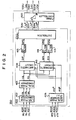
- a detailed arrangement of circuit 350 is shown in Fig. 2.
- reactor section 300 has delta-connected reactors.
- the same reference numerals as in Fig. I denote the same parts in Fig. 2.
- reference numeral 402 denotes a line/phase converter.
- Converter 402 converts load current signals iRL, iSL, and iTL detected as line currents in Fig. I into phase currents iUL, iSL, and iTL of the delta-connected reactors according to equations (I) below (the arithmetic operations by equations (I) are required for the delta-connected reactors and are not required for the star-connected reactors):
- Dual phase converter 403 converts current signals iUL, iVL, and iWL into dual phase current signals ildL and ilqL according to equations (2) below:
- Dual phase generator 406 comprises a phase locked loop circuit (PLL circuit) for receiving AC main line voltage signals eRS, eST, and eTR in Fig. I. If the first, second, and third phases are defined as the R, S, and T phases in Fig. I, PLL circuit 406 generates unit sinusoidal signal eldl* synchronized with interline voltage eRS between the first and second phases, unit sinusoidal signal elql * lagged by 90° from signal eldl * , and phase signal ⁇ ldl* of signal eldl *.
- Signals eldl * and elql * are defined by equations (3) (signals eldl * and elql * are synchronized with the first phase voltage signal when reactors in reactor section 300 are star-connected):
- Arithmetic circuit 408 receives signals ildL, ilqL, eld * , and elq* and calculates signal Qlp according to equation (4) below:
- signal Qlp is a pulsated signal including a DC component and an AC component oscillating at a frequency twice that of the fundamental wave.
- the DC component of Qlp represents the in-phase reactive current.
- DC filter 413 receives the DC component of signal Qlp and outputs it as signal QlpD.
- Signal QIpD is the in-phase reactive current signal.
- Arithmetic circuit 410 receives signals ildL, ilqL, eld * , and elq* and calculates signals QIN and PIN according to equations (5) below:
- load currents iRL, iSL, and iTL include the component currents obtained when the opposite inphase and opposite phase components
- Qlp and phase current included in first phase current iUL in PIN are pulsated signals.
- Signals Qlp and PIN are 55 equation (I) is separated into a component (PIND) filtered through DC filters 414 and 415 to detect DC having the same phase as that of the interline component signals QIND and PIND, respectively.
- voltage of the first and second phases and a com-The resultant signals QIND and PIND represent ponent (QIND) phase-shifted by 90° therefrom.
- PIND is referred to as an in-phase opposite phase current signal of the first phase
- QIND is referred to as a 90° opposite phase current signal of the first phase.
- Distributer 420A receives signals QIPD, QIND, and PIND and performs arithmetic operations to output current command values IU*, IV*, and IW" for designating currents supplied to reactor section 300 in Fig. I (The arrangement and operation of distributer 420A will be described in detail later with reference to Fig. 3).
- Firing controller 500 receives values IU * , IV*, and IW" and controls firing of thyristors 301U. 301V, and 30lW in section 300 to which currents - (fundamental wave components) designated by IU*, IV*, and IW* are supplied.
- reference numerals 421A and 424A denote arithmetic circuits. Circuits 421A and 424A receive signals QIND and PIND and perform arithmetic operations according to equations (6) and (7), to output 90° opposite phase current signal Q2ND of the second phase, in-phase opposite phase current signal P2ND of the second phase, and in-phase opposite phase current signal P3ND of the third phase:
- Signals P2ND and Q2ND respectively represent the in-phase component current (P2ND) and 90° phase-shifted current component (Q2ND) when the opposite phase component of second phase current iVL in equation (I) is separated into a component having the same phase as that of the interline voltage of the second and third phases and a 90° phase-shifted component.
- signals P3ND and Q3ND respectively represent an in-phase component current (P3ND) and a 90° phase-shifted current component - (Q3ND) when the opposite phase component of third phase current iWL in equation (I) is separated into a component having the same phase as that of the interline voltage of the third and first phases and a 90° phase-shifted component thereof.
- Setting circuit 437 outputs reactive current setting signal QIMAX to designate a maximum value of the reactive current (i.e., a phase lag) generated by reactor section 300 in Fig. I.
- Distributing section 430A receives in-phase reactive current signal QIPD detected from a load current of an arc furnace or the like, 90° opposite phase current signals QIND, Q2ND, and Q3ND of the first, second and third phases, in-phase opposite phase current signals PIND, P2ND, and P3ND of the first, second, and third phases, and reactive current setting signal QIMAX and performs arithmetic operations according to equations (8).
- Section 430A outputs current command IU * of the first phase for designating a current to be generated by reactor 302U in section 300 in Fig. I.
- section 430A outputs current commands IV* and IW* of the second and third phases for designating currents to be generated by reactors 302V and 302W, respectively.
- Section 430A is arranged in the following manner:
- Reference numeral 438A denotes an adder for performing an arithmetic operation (a subtraction) of signals QIMAX and QIPD in the illustrated polarity.
- An output from adder 438A corresponds to each first term in equations (8).
- Reference numerals 439A, 440A, and 441A denote adders for adding signals QIND, Q2ND, and Q3ND, the output signal from adder 438A, and output signals from adders 434A, 435A and 436A in the illustrated polarity (Fig. 3).
- Resultant signals IU*, IV * , and IW" are DC signals which include all information on in-phase currents and opposite phase currents.
- Reactor section 300 in Fig. I is controlled according to signals IU * , IV", and IW*. Even if the load currents from an arc furnace or the like include both in-phase and opposite phase components, currents at parts 4 in Fig. 5 can be arbitrarily balanced.
- dual phase generator 406 receives signals eRS, eST, and eTR and generates dual phase signals eld * and elq * according to equations (3).
- Signals iRL, iSL, and iTL detected as line currents are converted by line/phase converter 402 according to equations (I) into delta-connected phase currents iUL, iVL, and iWL (i.e., currents respectively flowing through delta-connected reactors 302U, 302V and 302W in reactor section 300 in Fig. I).
- Signals iUL, iVL, and iWL are converted by dual phase converter 403 according to equations (2) into dual phase signals ildL and ilqL.
- Arithmetic circuit 408 performs the arithmetic operation according to equation (4), to obtain signal QIP.
- Signal QIP is filtered by DC filter 413, to extract DC component signal QIPD.
- Extracted signal QIPD represents the in-phase current included in signals iRL, iSL, and iTL (i.e., iUL, iVL, and iWL in equations (I)).
- Arithmetic circuit 410 performs arithmetic operations according to equation (5) to obtain signals PIN and QIN. Signals PIN and QIN are filtered by DC filters 415 and 414 to extract DC component signals PIND and QIND, respectively.
- Signals PIND and QIND represent currents (i.e., the in-phase current component or PIND, and 90° phase-shifted current component or QIND) of components obtained when the opposite phase current included in first phase current iUL in equations (I) is separated into a component having the same phase as that of the interline voltage between the first and second phases and a component phase-shifted by 90° from that of the interline voltage (PIND is referred to as the in-phase opposite phase current of the first phase, and QIND is referred to as the 90° opposite phase current).
- Arithmetic operations according to equations - (6) and (7) are performed by arithmetic circuits 421A and 424A in distributer 420A, to obtain in- phase opposite phase current P2ND of the second phase, 90° opposite phase current Q2ND of the second phase, in-phase opposite phase current P3ND of the third phase, and 90° opposite phase current Q3ND of the third phase.
- Resultant signal QIPD is a signal associated with only the in-phase current included in load currents iRL, iSL, and iTL. More specifically, if its in-phase current is separated into effective and reactive components, it is associated with only the reactive current. QIPD is a signal associated with only the in-phase reactive current. Arithmetic operations of the required values concerning the in- phase current components, for example, the conversion in equation (6) or the like, can be performed with reference to any phase, to obtain identical results. Therefore, in-phase arithmetic operations need be performed for only one phase.
- signals PIND and QIND signals P2ND and Q2ND, and signals P3ND and Q3ND
- signals PIND and QIND are associated with only the opposite phase current components included in iUL, iVL, and iWL (i.e., iRL, iSL, and iTL) in equations (I). More specifically, signals PIND and QIND are associated with only the opposite phase of current iUL; P2ND and Q2ND, with the opposite phase of iVL; and P3ND and Q3ND, with the opposite phase of iWL.
- PIND is the current component having the same phase as that of the interline voltage in the opposite phase of current iUL
- QIND is a signal associated with only the current component having a phase which is shifted by 90° from that of the interline voltage.
- the resultant signals are supplied to distributing section 430A in Fig. 3 according to equations - (8), to output current commands-IU*, IV * , and IW".
- currents of reactor section 300 in Fig. I are controlled on the basis of commands IU*, IV * , and IW*.
- the phases of the opposite phase currents in the compensation currents generated by section 300 are controlled to cancel the opposite phase currents of the currents generated by the arc furnace.
- the opposite phase currents from the arc furnace are cancelled by the compensation currents at lines 51R, 51S, and 51T. Therefore, the opposite phase currents do not flow toward power supply I, thereby balancing the current of power supply I.
- the output signal from adder 438A in Fig. 3 is used for control.
- a sum of the in-phase reactive components (lag) of the currents generated by the load and the in-phase reactive components (lag) of the compensation currents generated by reactor section 300, is controlled to be equal to reactive current setting signal QIMAX (lag) in Fig. 3.
- the reactive currents having a predetermined time lag are cancelled by the advanced reactive current of phase advance capacitor section 200 in Fig. I.
- the reactive currents do not flow toward AC power supply I in Fig. I. Only the in-phase effective currents generated by the load flow in the AC power supply.
- Fig. 4 shows a modification of distributer 420A in Fig. 3.
- the distributer of Fig. 4 is used in place of distributor 420A in Fig. 2.
- This modification includes the same part as in the previous embodiment, and the same description will therefore be omitted.
- the same reference numerals as in Fig. 2 denote the same parts in Fig. 4.
- reference numerals 4218 and 424B denote arithmetic circuits.
- Circuits 421B and 424B respectively receive 90° opposite phase current signal QIND of the first phase and in-phase opposite phase current signal PIND of the first phase, and perform arithmetic operations according to equations (9) and (10), to output 90° opposite phase current signal Q2ND of the second phase and 90° opposite phase current signal Q3ND of the third phase.
- Signals Q2ND and Q3ND are the same as those obtained by equations (6) and (7).
- Setting circuit 437 outputs reactive current setting signal QIMAX.
- Distributing section 430B receives in-phase reactive current signal QIPD, and 90° opposite phase current signals QIND, Q2ND, and Q3ND of the first, second, and third phases, reactive current-setting signal QIMAX, and performs arithmetic operations according to equations (II), to output current commands IU * , IV", and IW* of the first, second, and third phases.
- Reference numerals 446B, 447B, and 448B denote coefficient circuits, each of which doubles the corresponding input signal; and 438A, 439B, 440B, and 441B denote adders for adding input signals in the illustrated polarities in Fig. 4.
- arithmetic operations in arithmetic circuits 421B and 424B can be simpler than those in arithmetic circuits 421A and 424A of Fig. 3.
- reference numerals 421C and 424C denote arithmetic circuits, respectively.
- Circuits 421C and 424C respectively receive 90° opposite phase current signal QIND of the first phase and in-phase opposite phase current signal PIND of the first phase, and perform arithmetic operations according to equations (12) and (13) to output in-phase opposite phase current signal P2ND of the second phase, and in-phase opposite phase current signal P3ND of the third phase.
- Signals P2ND and P3ND are the same as those obtained by equations (6) and (7).
- Reference numeral 437 denotes a setting circuit for outputting reactive current-setting signal QIMAX; and 430C, a distributing section. Section 430C receives in-phase reactive current signal QIPD, in-phase opposite phase current signals PIND, P2ND, and P3ND of the first, second, and third phases, reactive current setting signal QIMAX, and performs arithmetic operations according to equations (14), to output current commands IU * , IV*, and IW* of the first, second, and third phases.
- Reference numerals 431A, 432A, and 433A denote coefficient circuits, each of which multiplies the corresponding input signal by I/ ⁇ 3.
- Reference numerals 446B; 447B, and 448B denote coefficient circuits each of which doubles the corresponding input signal.
- Reference numerals 438A, 439B, 4408, 441B, 434A, 435A, and 436A denote adders which perform additions at the illustrated polarities in Fig. 5.
- arithmetic operations in arithmetic circuits 421C and 424C can be simpler than those in arithmetic circuits 421A and 424A of Fig. 3.
- reactors in reactor section 300 are delta-connected.
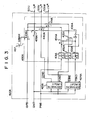
- the same parts as in Fig. 2 denote the same parts in Fig. 6.
- Reference numeral 406A denotes a dual phase generator constituted by a phase-locked loop circuit (PLL circuit) for receiving AC main line voltage signals eRS, eST, and eTR. If the first, second, and third phases are the R, S, and T phases, respectively, as shown in Fig. I, generator 406A outputs unit sinusoidal signal eldl * synchronized with an interline voltage between the first and second phases, unit sinusoidal signal elql * advanced by 90° therefrom, and phase signal oldl * thereof.
- Signals eldl * and elql * are represented by equations 3-(A) (signals eldl * and elql * are synchronized with the voltages of the first phase if reactors in reactor section 300 in Fig. I are star-connected):
- Dual phase generator 406A has the internal arrangement shown in Fig. 7.
- Three-phase voltage signals eRS, eST, and eTR are converted by 3/2 phase converter 4060 into unit cosine signal ed*cos ⁇ * and unit sinusoidal signal ed*sine ⁇ *.
- Signal ed * coso * is multiplied by multiplier 4061, with cosine signal cosoldl * from D/A converter 4067A.
- Signal ed*sin ⁇ * is multiplied by multiplier 4062, with the sinusoidal signal from D/A converter 4068A.
- Subtracter 4063 calculates a difference between the output (ed*sin ⁇ *sin ⁇ ldl*) from multiplier 4062 and the output (ed*cos ⁇ *cos ⁇ ldl*) from multiplier 4061.
- the difference output is input to proportional integral (PI) amplifier 4064.
- a DC output from PI amplifier 4064 is converted by V/F converter 4065 into a signal having a frequency corresponding to the DC output level. This frequency signal is counted by counter 4066, to produce phase signal ⁇ ldl*.
- Signal ⁇ ldl* is input as address data, to function ROMs 4067 and 4068.
- ROM 4067 outputs data corresponding to cos ⁇ ldl* from a memory area at the address corresponding to coseldl *.
- Data coseldl * is converted by D/A converter 4067A into analog signal cosoldl * which is then supplied to multiplier 4061.
- ROM 4068 outputs data corresponding to sineldl * from the memory area at the address corresponding to data eldl * .
- Data sin ⁇ ldl* is converted by D/A converter 4068A into analog signal sin ⁇ ldl* which is then supplied to multiplier 4062.
- the circuit in Fig. 7 constitutes a phase-locked loop, so as to minimize the magnitude of the input to amplifier 4064, thereby obtaining stable phase signal ⁇ ldl*.
- Reference numeral 407 denotes a dual phase generator for receiving phase angle signal ⁇ ldl*, and outputs dual phase voltage signals eld2 * and elq2 * each having a frequency twice the AC main line voltage frequency.
- Signals eld2* and elq2 * are calculated by the following equations, respectively:
- Reference numeral 404 denotes an arithmetic circuit for receiving signals ildL, ilqL, eldr, and elql*, and calculating signals QIN and PIN according to equations (5A) below:
- QIN and PIN are pulsated currents including a DC component and AC components oscillated at a frequency twice the fundamental wave frequency.
- Reference numeral 409 denotes a separator.
- Separator 409 comprises DC filters 410F and 411F, and adders 412F and 413F. Separator 409 receives signals QIN and PIN and causes filters 410F and 411F to detect the DC components of QIN and PIN and output them as signals QIND and PIND. Adders 412F and 413 remove the DC components, i.e., QIND and PIND, from signals QIN and PIN, so that only the AC components are output as signals QINA and PINA.
- the resultant PIND and QIND represent currents of components obtained when the opposite phase current included in first phase current iUL in equation (I) is separated into a component (i.e., PIND) having the same phase as that of the interline voltage between the first and second phases and a 90° phase-shifted component therefrom.
- PIND is an in-phase opposite phase current signal of the first phase
- QIND is a 90° opposite phase current signal of the first phase.
- Reference numeral 408A denotes an arithmetic circuit for inputting signals QINA, PINA, eld2 * , and elq2 * and calculating signal QIPD according to equation (6A) below:
- Signal QIPD is a DC signal and represents an in-phase reactive current included in each load current iRL, iSL, or iTL.
- Reference numeral 420A denotes a distributing section for receiving signals QIPD, QIND, and PIND, and outputting current commands IU * , IV*, and IW* designating currents flowing through reactor section 300 in Fig. I.
- the contents of section 420A can be the same as those in Fig. 3.
- Reference numeral 500 denotes a firing controller for receiving current commands IU * , IV*, and IW* and controlling the firing of thyristors 301U, 301V, and 301W so as to flow the currents designated by the commands through reactor section 300.
- Fig. I currents from an arc furnace are detected as signals iRL, iSL, and iTL. These currents are unbalanced currents including in- phase and opposite phase components.
- Power supply main line voltage connected to the arc furnace are detected as signals eRS, eST, and eTR which are then supplied to reactive power compensator apparatus 100.
- dual phase generator 406A receives signals eRS, eST, and eTR, and calculates and outputs dual phase signals eldl * and elql * and phase signal oldl * of the former phase signal according to equations (3A). Subsequently, dual phase generator 407 receives signal 8ldl* and generates dual signals eld2 * and elq2 * according to equations (4A).
- signals iRL, iSL, and iTL detected as line currents are converted by line/phase converter 402 according to equations (I), to produce delta-connected phase currents iUL, iVL, and iWL (i.e., currents flowing through reactors 302U, 302V, and 302W if the reactors in section 300 are delta-connected as in Fig. I).
- Signals iUL, iVL, and iWL are converted by dual phase converter 403 according to equations (2), thereby producing dual phase signals ildL and ilqL.
- Arithmetic circuit 404A performs arithmetic operations according to equations (5A), to produce signals QIN and PIN. These signals are separated by separator 409 into DC component signals QIND and PIND, and AC component signals QINA ' and PINA.
- Result signals QIND and PIND represent currents (i.e., an in-phase current component or PIND, and a 90° phase-shifted current component or QIND) obtained by separating the opposite phase current included in first phase current iUL into a component having the same phase as that of an interline voltage between the first and second phases and a 90° phase-shifted component (PIND is referred to as the in-phase opposite phase current of the first phase, and QIND is referred to as the 90° opposite phase current of the first phase).
- currents i.e., an in-phase current component or PIND, and a 90° phase-shifted current component or QIND
- Arithmetic circuit 408A receives signals ⁇ ld2*, elq2 * , QINA, and PINA, and performs arithmetic operation according to equation (6A), to obtain DC signal QIPD.
- This signal represents an in-phase reactive component current included in signal iRL, iSL, or iTL (or iUL, iVL, or iWL in equations (I)).
- Arithmetic operations according to equations - (9), (10), (II), (12), and (13) are performed by arithmetic circuits 421A and 424A in distributer 420A to obtain in-phase opposite phase current P2ND of the second phase, 90° opposite phase current Q2ND of the second phase, inphase opposite phase current P3ND of the third phase, and 90° opposite phase current Q3ND of the third phase.
- Resultant signal QIPD is a signal associated with only the in-phase current included in load currents iRL, iSL, and iTL. More specifically, if its in-phase current is separated into effective and reactive components, it is associated with only the reactive current. Thus, QIPD is a signal associated with only the in-phase reactive current. Arithmetic operations of the required values concerning the in- phase current components, e.g., conversion in equation (6A) or the like, can be performed with reference to any phase, to obtain identical results. Therefore, in-phase arithmetic operations need be performed for only one phase.
- signals PIND and QIND signals P2ND and Q2ND, and signals P3ND and Q3ND
- signals PIND and QlND are associated with only the opposite phase of current iUL: P2ND and Q2ND, the opposite phase of iVL; and P3ND and Q3ND, the opposite phase of iWL.
- PIND and QIND PIND is the current component having the same phase as that of the interline voltage in the opposite phase of current iUL,.
- QIND is a signal associated with only the current component having a phase which is shifted by 90° from that of the interline voltage.
- the resultant signals are supplied to distributing section 430A in Fig. 3 according to equations - (8), to output current commands IU * , IV", and IW".
- currents of reactor section 300 in Fig. I are controlled on the basis of commands IU * , IV * , and IW*.
- the phases of the opposite phase currents in the compensation currents generated by section 300 are controlled to cancel the opposite phase currents of the currents generated by the arc furnace.
- the opposite phase currents from the arc furnace are cancelled by the compensation currents at lines 51R, 51S, and 51T. Therefore, the opposite phase currents do not flow toward power supply I, thereby balancing the current of power supply I.
- an output signal from adder 438A in Fig. 3 is used for control.
- a sum of the in-phase reactive components (lag) of the currents generated by the load and the in- phase reactive components (lag) of the compensation currents generated by reactor section 300 is controlled to be equal to reactive current setting signal QIMAX (lag) in Fig. 3.
- the reactive currents having a predetermined time lag are cancelled by the advanced reactive current of phase advance capacitor section 200 in Fig. I.
- the reactive currents do not flow toward AC power supply I in Fig. I. Only the in-phase effective currents generated by the load flow in the AC power supply.
- the reactive power compensation apparatus provides the following effects:
Landscapes
- Engineering & Computer Science (AREA)
- Power Engineering (AREA)
- Control Of Electrical Variables (AREA)
- Supply And Distribution Of Alternating Current (AREA)
Applications Claiming Priority (4)
| Application Number | Priority Date | Filing Date | Title |
|---|---|---|---|
| JP60200012A JPH0625951B2 (ja) | 1985-09-10 | 1985-09-10 | 無効電力補償装置 |
| JP200010/85 | 1985-09-10 | ||
| JP200012/85 | 1985-09-10 | ||
| JP60200010A JPH0625949B2 (ja) | 1985-09-10 | 1985-09-10 | 無効電力補償装置 |
Publications (3)
| Publication Number | Publication Date |
|---|---|
| EP0214661A2 true EP0214661A2 (de) | 1987-03-18 |
| EP0214661A3 EP0214661A3 (en) | 1988-03-23 |
| EP0214661B1 EP0214661B1 (de) | 1992-03-11 |
Family
ID=26511907
Family Applications (1)
| Application Number | Title | Priority Date | Filing Date |
|---|---|---|---|
| EP86112529A Expired - Lifetime EP0214661B1 (de) | 1985-09-10 | 1986-09-10 | Blindleistungskompensator |
Country Status (5)
| Country | Link |
|---|---|
| US (1) | US4698581A (de) |
| EP (1) | EP0214661B1 (de) |
| AU (1) | AU573101B2 (de) |
| CA (1) | CA1300222C (de) |
| DE (1) | DE3684207D1 (de) |
Cited By (12)
| Publication number | Priority date | Publication date | Assignee | Title |
|---|---|---|---|---|
| EP0259805A3 (en) * | 1986-09-11 | 1989-02-22 | Kabushiki Kaisha Toshiba | Reactive power compensation apparatus |
| EP0483405A1 (de) * | 1990-10-31 | 1992-05-06 | Nkk Corporation | Einrichtung zur Flimmerkompensation für einen Gleichstromlichtbogenofen |
| US5155740A (en) * | 1990-10-22 | 1992-10-13 | Nkk Corporation | Flicker compensating apparatus for DC arc furnace |
| RU2212086C2 (ru) * | 2001-10-16 | 2003-09-10 | ООО "ЭЛМЕХтранс А" | Устройство для компенсации реактивной мощности |
| WO2006024164A2 (en) | 2004-09-01 | 2006-03-09 | Hatch Ltd. | System and method for controlling power across multiple electrodes in a furnace |
| WO2010037616A1 (de) * | 2008-09-30 | 2010-04-08 | Siemens Aktiengesellschaft | Stromversorgungsanlage für einen drehstrom-lichtbogenofen mit zwischenkreisumrichter zwischen netzanschluss und ofentransformator |
| RU2467893C1 (ru) * | 2011-04-19 | 2012-11-27 | Федеральное государственное бюджетное образовательное учреждение высшего профессионального образования "Дальневосточный государственный университет путей сообщения" (ДВГУПС) | Устройство для компенсации реактивной мощности электроподвижного состава |
| RU2506677C1 (ru) * | 2012-07-05 | 2014-02-10 | Федеральное государственное бюджетное образовательное учреждение высшего профессионального образования "Дальневосточный государственный университет путей сообщения" (ДВГУПС) | Устройство для компенсации реактивной мощности |
| RU2595265C1 (ru) * | 2015-08-10 | 2016-08-27 | Федеральное государственное бюджетное образовательное учреждение высшего образования "Дальневосточный государственный университет путей сообщения" (ДВГУПС) | Устройство для компенсации реактивной мощности электроподвижного состава |
| RU2729500C1 (ru) * | 2019-04-22 | 2020-08-07 | Акционерное общество "Научно-исследовательский институт железнодорожного транспорта" | Способ управления режимами тяги, выбега и горячего отстоя железнодорожного электроподвижного состава с входным однофазным широтно-импульсным преобразователем напряжения на его стоянке |
| CN111537875A (zh) * | 2020-06-01 | 2020-08-14 | 泉州睿郎机电技术有限公司 | 双电源转换开关触头转换时间采集测定方法及其装置 |
| RU2749606C1 (ru) * | 2020-08-31 | 2021-06-16 | Владимир Степанович Климаш | Способ трехступенчатого регулирования реактивной мощности конденсаторной установкой |
Families Citing this family (13)
| Publication number | Priority date | Publication date | Assignee | Title |
|---|---|---|---|---|
| JPH0789715B2 (ja) * | 1986-09-11 | 1995-09-27 | 株式会社東芝 | 無効電力補償装置 |
| US5121048A (en) * | 1990-10-29 | 1992-06-09 | Electric Power Research Institute | Feedback control system for static volt ampere reactive compensator with thyristor controlled reactances |
| DE4436353C2 (de) * | 1994-10-12 | 1997-02-06 | Abb Management Ag | Verfahren zur Stabilisierung eines Wechselstromnetzes gegen Blindlastschwankungen und Blindleistungskompensationseinrichtung |
| US5710492A (en) * | 1994-12-22 | 1998-01-20 | Hitachi, Ltd. | Apparatus for monitoring and stabilizing power swing in a power system by utilizing a power electronics technique |
| US5991327A (en) * | 1995-10-26 | 1999-11-23 | Inverpower Controls Ltd. | Smart predictive line controller for AC and DC electric arc furnaces |
| US5818208A (en) * | 1996-12-19 | 1998-10-06 | Abb Power T&D Company Inc. | Flicker controllers using voltage source converters |
| DE19845851A1 (de) * | 1998-10-05 | 2000-04-06 | Asea Brown Boveri | Verfahren und Regelungseinrichtung zur Stabilisierung eines Stromversorgungsnetzes |
| US6121758A (en) * | 1999-06-23 | 2000-09-19 | Daq Electronics, Inc. | Adaptive synchronous capacitor switch controller |
| US6274851B1 (en) | 1999-08-31 | 2001-08-14 | Inverpower Controls Ltd. | Electric arc furnace controller |
| RU2256994C1 (ru) * | 2004-02-05 | 2005-07-20 | Закрытое акционерное общество "Отраслевой центр внедрения новой техники и технологий" | Устройство для компенсации реактивной мощности |
| US7288921B2 (en) * | 2004-06-25 | 2007-10-30 | Emerson Process Management Power & Water Solutions, Inc. | Method and apparatus for providing economic analysis of power generation and distribution |
| US20080056327A1 (en) * | 2006-08-30 | 2008-03-06 | Hatch Ltd. | Method and system for predictive electrode lowering in a furnace |
| RU169039U1 (ru) * | 2016-02-18 | 2017-03-02 | Федеральное Государственное Автономное Образовательное Учреждение Высшего Профессионального Образования "Сибирский Федеральный Университет" (Сфу) | Фильтрокомпенсирующая установка для системы тягового электроснабжения переменного тока |
Family Cites Families (5)
| Publication number | Priority date | Publication date | Assignee | Title |
|---|---|---|---|---|
| FR2266347B1 (de) * | 1974-03-27 | 1982-07-02 | Siemens Ag | |
| US3963978A (en) * | 1975-02-14 | 1976-06-15 | General Electric Company | Reactive power compensator |
| US4437052A (en) * | 1981-12-17 | 1984-03-13 | Westinghouse Electric Corp. | Static VAR generator |
| JPS59139416A (ja) * | 1983-01-28 | 1984-08-10 | Nissin Electric Co Ltd | 無効電力補償装置 |
| JPS63622A (ja) * | 1986-06-19 | 1988-01-05 | Fujitsu Ltd | デ−タ結合実行制御方式 |
-
1986
- 1986-09-04 AU AU62349/86A patent/AU573101B2/en not_active Ceased
- 1986-09-05 US US06/903,957 patent/US4698581A/en not_active Expired - Fee Related
- 1986-09-09 CA CA000517797A patent/CA1300222C/en not_active Expired - Lifetime
- 1986-09-10 DE DE8686112529T patent/DE3684207D1/de not_active Expired - Lifetime
- 1986-09-10 EP EP86112529A patent/EP0214661B1/de not_active Expired - Lifetime
Non-Patent Citations (3)
| Title |
|---|
| IEEE Trans. on Power Apparatus Systems, vol PAS-97, no 5 (1978) pp. 1935-1944 * |
| IEEE TRANSACTIONS ON INDUSTRY APPLICATIONS, vol. IA-20, no. 3, part 1, May-June 1984, pages 625-630, IEEE, New York, US; H. AKAGI et al.: "Instantaneous reactive power compensators comprising switching devices without energy storage components" * |
| SIEMENS FORSCHUNGS UND ENTWICKLUNGSBERICHT, vol. 6, no. 1, 1977, pages 29-38, Springer-Verlag, Berlin, DE; W. MEUSEL et al.: "Coordinate transformations of multi-term regulation systems for the compensation and symmetrization of three-phase supplies" * |
Cited By (15)
| Publication number | Priority date | Publication date | Assignee | Title |
|---|---|---|---|---|
| EP0259805A3 (en) * | 1986-09-11 | 1989-02-22 | Kabushiki Kaisha Toshiba | Reactive power compensation apparatus |
| US5155740A (en) * | 1990-10-22 | 1992-10-13 | Nkk Corporation | Flicker compensating apparatus for DC arc furnace |
| EP0483405A1 (de) * | 1990-10-31 | 1992-05-06 | Nkk Corporation | Einrichtung zur Flimmerkompensation für einen Gleichstromlichtbogenofen |
| RU2212086C2 (ru) * | 2001-10-16 | 2003-09-10 | ООО "ЭЛМЕХтранс А" | Устройство для компенсации реактивной мощности |
| WO2006024164A2 (en) | 2004-09-01 | 2006-03-09 | Hatch Ltd. | System and method for controlling power across multiple electrodes in a furnace |
| EP1810550A4 (de) * | 2004-09-01 | 2013-08-28 | Hatch Ltd | System und verfahren zur leistungsregelung über mehrere elektroden in einem ofen |
| US8933378B2 (en) | 2008-09-30 | 2015-01-13 | Siemens Aktiengesellschaft | Power supply system for a polyphase arc furnace with an indirect converter between a mains connection and a furnace transformer |
| WO2010037616A1 (de) * | 2008-09-30 | 2010-04-08 | Siemens Aktiengesellschaft | Stromversorgungsanlage für einen drehstrom-lichtbogenofen mit zwischenkreisumrichter zwischen netzanschluss und ofentransformator |
| RU2477588C2 (ru) * | 2008-09-30 | 2013-03-10 | Сименс Акциенгезелльшафт | Установка электроснабжения для трехфазной дуговой электропечи с двухзвенным преобразователем переменного тока между присоединением к сети и трансформатором печи |
| RU2467893C1 (ru) * | 2011-04-19 | 2012-11-27 | Федеральное государственное бюджетное образовательное учреждение высшего профессионального образования "Дальневосточный государственный университет путей сообщения" (ДВГУПС) | Устройство для компенсации реактивной мощности электроподвижного состава |
| RU2506677C1 (ru) * | 2012-07-05 | 2014-02-10 | Федеральное государственное бюджетное образовательное учреждение высшего профессионального образования "Дальневосточный государственный университет путей сообщения" (ДВГУПС) | Устройство для компенсации реактивной мощности |
| RU2595265C1 (ru) * | 2015-08-10 | 2016-08-27 | Федеральное государственное бюджетное образовательное учреждение высшего образования "Дальневосточный государственный университет путей сообщения" (ДВГУПС) | Устройство для компенсации реактивной мощности электроподвижного состава |
| RU2729500C1 (ru) * | 2019-04-22 | 2020-08-07 | Акционерное общество "Научно-исследовательский институт железнодорожного транспорта" | Способ управления режимами тяги, выбега и горячего отстоя железнодорожного электроподвижного состава с входным однофазным широтно-импульсным преобразователем напряжения на его стоянке |
| CN111537875A (zh) * | 2020-06-01 | 2020-08-14 | 泉州睿郎机电技术有限公司 | 双电源转换开关触头转换时间采集测定方法及其装置 |
| RU2749606C1 (ru) * | 2020-08-31 | 2021-06-16 | Владимир Степанович Климаш | Способ трехступенчатого регулирования реактивной мощности конденсаторной установкой |
Also Published As
| Publication number | Publication date |
|---|---|
| CA1300222C (en) | 1992-05-05 |
| EP0214661A3 (en) | 1988-03-23 |
| AU6234986A (en) | 1987-03-12 |
| DE3684207D1 (de) | 1992-04-16 |
| AU573101B2 (en) | 1988-05-26 |
| EP0214661B1 (de) | 1992-03-11 |
| US4698581A (en) | 1987-10-06 |
Similar Documents
| Publication | Publication Date | Title |
|---|---|---|
| EP0214661B1 (de) | Blindleistungskompensator | |
| US3999117A (en) | Method and control apparatus for static VAR generator and compensator | |
| US5212630A (en) | Parallel inverter system | |
| US5091839A (en) | Method and apparatus for supplying voltage to a three-phase voltage system having a load-carrying neutral conductor with a pulse width modulated three phase invertor | |
| US4529925A (en) | Reactive power compensating cycloconverter | |
| US4755738A (en) | Reactive power compensation apparatus | |
| JP4056852B2 (ja) | 電力変換装置 | |
| US5182463A (en) | 3-Phase converter apparatus | |
| US6225791B1 (en) | Controller for performing a decoupling control of a transformerless reactive series compensator | |
| US4234842A (en) | Voltage regulator and flicker compensator | |
| US5065304A (en) | Controller for AC power converter | |
| US4000455A (en) | Fast current measurement apparatus for static VAR generator compensator control circuit and method for using same | |
| Mendalek et al. | A non-linear optimal predictive control of a shunt active power filter | |
| Matsui et al. | A detecting method for active-reactive-negative-sequence powers and its application | |
| JPH01270791A (ja) | 誘導電動機の速度制御装置 | |
| JPH0625951B2 (ja) | 無効電力補償装置 | |
| EP0186513B1 (de) | Steuerungsverfahren für einen Zyklokonverter und Einrichtung dafür | |
| JPH0698469A (ja) | 電圧検出形無効電力補償装置の制御方式 | |
| Jiao et al. | A novel phase-locked loop based four-leg converter control for unbalanced load compensation under distorted and unbalanced grid condition | |
| JP2575682B2 (ja) | 無効電力補償装置 | |
| JPH0625949B2 (ja) | 無効電力補償装置 | |
| JP2827484B2 (ja) | インバータ制御回路 | |
| JPH04344128A (ja) | 不平衡補償装置 | |
| JPS6369433A (ja) | 無効電力補償装置 | |
| JPH0833784B2 (ja) | 無効電力補償装置の制御方式 |
Legal Events
| Date | Code | Title | Description |
|---|---|---|---|
| PUAI | Public reference made under article 153(3) epc to a published international application that has entered the european phase |
Free format text: ORIGINAL CODE: 0009012 |
|
| 17P | Request for examination filed |
Effective date: 19860910 |
|
| AK | Designated contracting states |
Kind code of ref document: A2 Designated state(s): CH DE GB LI SE |
|
| PUAL | Search report despatched |
Free format text: ORIGINAL CODE: 0009013 |
|
| AK | Designated contracting states |
Kind code of ref document: A3 Designated state(s): CH DE GB LI SE |
|
| 17Q | First examination report despatched |
Effective date: 19900615 |
|
| RBV | Designated contracting states (corrected) |
Designated state(s): DE GB SE |
|
| GRAA | (expected) grant |
Free format text: ORIGINAL CODE: 0009210 |
|
| AK | Designated contracting states |
Kind code of ref document: B1 Designated state(s): DE GB SE |
|
| REF | Corresponds to: |
Ref document number: 3684207 Country of ref document: DE Date of ref document: 19920416 |
|
| PLBE | No opposition filed within time limit |
Free format text: ORIGINAL CODE: 0009261 |
|
| STAA | Information on the status of an ep patent application or granted ep patent |
Free format text: STATUS: NO OPPOSITION FILED WITHIN TIME LIMIT |
|
| 26N | No opposition filed | ||
| PGFP | Annual fee paid to national office [announced via postgrant information from national office to epo] |
Ref country code: GB Payment date: 19940831 Year of fee payment: 9 |
|
| EAL | Se: european patent in force in sweden |
Ref document number: 86112529.2 |
|
| PG25 | Lapsed in a contracting state [announced via postgrant information from national office to epo] |
Ref country code: GB Effective date: 19950910 |
|
| GBPC | Gb: european patent ceased through non-payment of renewal fee |
Effective date: 19950910 |
|
| PGFP | Annual fee paid to national office [announced via postgrant information from national office to epo] |
Ref country code: SE Payment date: 19970918 Year of fee payment: 12 |
|
| PGFP | Annual fee paid to national office [announced via postgrant information from national office to epo] |
Ref country code: DE Payment date: 19970919 Year of fee payment: 12 |
|
| PG25 | Lapsed in a contracting state [announced via postgrant information from national office to epo] |
Ref country code: SE Free format text: LAPSE BECAUSE OF NON-PAYMENT OF DUE FEES Effective date: 19980911 |
|
| EUG | Se: european patent has lapsed |
Ref document number: 86112529.2 |
|
| PG25 | Lapsed in a contracting state [announced via postgrant information from national office to epo] |
Ref country code: DE Free format text: LAPSE BECAUSE OF NON-PAYMENT OF DUE FEES Effective date: 19990701 |