EP0214670A2 - Verfahren zum Befestigen von Stopfen innerhalb eines Rohres und so erhaltenes Verschlusssystem - Google Patents
Verfahren zum Befestigen von Stopfen innerhalb eines Rohres und so erhaltenes Verschlusssystem Download PDFInfo
- Publication number
- EP0214670A2 EP0214670A2 EP86112648A EP86112648A EP0214670A2 EP 0214670 A2 EP0214670 A2 EP 0214670A2 EP 86112648 A EP86112648 A EP 86112648A EP 86112648 A EP86112648 A EP 86112648A EP 0214670 A2 EP0214670 A2 EP 0214670A2
- Authority
- EP
- European Patent Office
- Prior art keywords
- tubular member
- plug
- tube
- mandrel
- cross
- Prior art date
- Legal status (The legal status is an assumption and is not a legal conclusion. Google has not performed a legal analysis and makes no representation as to the accuracy of the status listed.)
- Granted
Links
Images

Classifications
-
- F—MECHANICAL ENGINEERING; LIGHTING; HEATING; WEAPONS; BLASTING
- F16—ENGINEERING ELEMENTS AND UNITS; GENERAL MEASURES FOR PRODUCING AND MAINTAINING EFFECTIVE FUNCTIONING OF MACHINES OR INSTALLATIONS; THERMAL INSULATION IN GENERAL
- F16L—PIPES; JOINTS OR FITTINGS FOR PIPES; SUPPORTS FOR PIPES, CABLES OR PROTECTIVE TUBING; MEANS FOR THERMAL INSULATION IN GENERAL
- F16L13/00—Non-disconnectable pipe joints, e.g. soldered, adhesive, or caulked joints
- F16L13/14—Non-disconnectable pipe joints, e.g. soldered, adhesive, or caulked joints made by plastically deforming the material of the pipe, e.g. by flanging, rolling
-
- F—MECHANICAL ENGINEERING; LIGHTING; HEATING; WEAPONS; BLASTING
- F28—HEAT EXCHANGE IN GENERAL
- F28F—DETAILS OF HEAT-EXCHANGE AND HEAT-TRANSFER APPARATUS, OF GENERAL APPLICATION
- F28F11/00—Arrangements for sealing leaky tubes and conduits
- F28F11/02—Arrangements for sealing leaky tubes and conduits using obturating elements, e.g. washers, inserted and operated independently of each other
-
- B—PERFORMING OPERATIONS; TRANSPORTING
- B21—MECHANICAL METAL-WORKING WITHOUT ESSENTIALLY REMOVING MATERIAL; PUNCHING METAL
- B21D—WORKING OR PROCESSING OF SHEET METAL OR METAL TUBES, RODS OR PROFILES WITHOUT ESSENTIALLY REMOVING MATERIAL; PUNCHING METAL
- B21D39/00—Application of procedures in order to connect objects or parts, e.g. coating with sheet metal otherwise than by plating; Tube expanders
- B21D39/04—Application of procedures in order to connect objects or parts, e.g. coating with sheet metal otherwise than by plating; Tube expanders of tubes with tubes; of tubes with rods
-
- F—MECHANICAL ENGINEERING; LIGHTING; HEATING; WEAPONS; BLASTING
- F16—ENGINEERING ELEMENTS AND UNITS; GENERAL MEASURES FOR PRODUCING AND MAINTAINING EFFECTIVE FUNCTIONING OF MACHINES OR INSTALLATIONS; THERMAL INSULATION IN GENERAL
- F16L—PIPES; JOINTS OR FITTINGS FOR PIPES; SUPPORTS FOR PIPES, CABLES OR PROTECTIVE TUBING; MEANS FOR THERMAL INSULATION IN GENERAL
- F16L55/00—Devices or appurtenances for use in, or in connection with, pipes or pipe systems
- F16L55/10—Means for stopping flow in pipes or hoses
- F16L55/12—Means for stopping flow in pipes or hoses by introducing into the pipe a member expandable in situ
- F16L55/128—Means for stopping flow in pipes or hoses by introducing into the pipe a member expandable in situ introduced axially into the pipe or hose
- F16L55/13—Means for stopping flow in pipes or hoses by introducing into the pipe a member expandable in situ introduced axially into the pipe or hose the closure device being a plug fixed by plastic deformation
-
- F—MECHANICAL ENGINEERING; LIGHTING; HEATING; WEAPONS; BLASTING
- F28—HEAT EXCHANGE IN GENERAL
- F28F—DETAILS OF HEAT-EXCHANGE AND HEAT-TRANSFER APPARATUS, OF GENERAL APPLICATION
- F28F9/00—Casings; Header boxes; Auxiliary supports for elements; Auxiliary members within casings
- F28F9/02—Header boxes; End plates
- F28F9/0202—Header boxes having their inner space divided by partitions
- F28F9/0204—Header boxes having their inner space divided by partitions for elongated header box, e.g. with transversal and longitudinal partitions
- F28F9/0209—Header boxes having their inner space divided by partitions for elongated header box, e.g. with transversal and longitudinal partitions having only transversal partitions
- F28F9/0212—Header boxes having their inner space divided by partitions for elongated header box, e.g. with transversal and longitudinal partitions having only transversal partitions the partitions being separate elements attached to header boxes
-
- F—MECHANICAL ENGINEERING; LIGHTING; HEATING; WEAPONS; BLASTING
- F28—HEAT EXCHANGE IN GENERAL
- F28F—DETAILS OF HEAT-EXCHANGE AND HEAT-TRANSFER APPARATUS, OF GENERAL APPLICATION
- F28F2220/00—Closure means, e.g. end caps on header boxes or plugs on conduits
Definitions
- the present invention relates to a method of fastening of baffles, serving as closing baffles or to divert medium flow, inside tubular members, and a closing system provided by such a method.
- the invention relates more particularly to closing baffles formed in situ inside an aluminum tube.
- baffles are installed in order to block or divert the flow of liquid/gas through the tube.
- baffles are provided by a brazing or soldering operation requiring use of heat and representing introduction of foreign materials (solder, flux) into the tube. Close temperature control is necessary, especially in the case of brazing, in order to avoid an overheating and consequently collapse of the tube. Furthermore, the introduction of foreign material (fluxes) will often promote corrosion attack on the tube.
- Another object of the invention is to provide closing baffles for tubular members regardless the shape or location of the tubular member in heat exchanging units and even where access to the tubular member void is restricted only to one end.
- tubular member means any hollow shape suitable for the intended purpose, e.g. the tubular member may comprise a hollow shape of circular, elliptical (oval) or rectangular cross-section with single or multiple cavity (voids).
- a method of fastening of baffles inside tubular members comprising steps of providing an expanding member in form of a cup-shaped plug having diverging walls and a cross-section complementary-shaped to the tubular member's cross-section, attaching the said plug to an expansion mandrel by crimping of its diverging walls around the conical head of the mandrel in a conforming die, insertion of the mandrel with plug into the tubular member's void on a desired location preterminated by the position of a support die attached to the mandrel and expansion of the plug into a firm engagement with the tubular member wall by withdrawal of the mandrel from the plug.
- a closing system for tubular members comprising an expanded member having a cross-section essentially complementary-shaped to the inner cross-section of the tubular member and extending circumferentially into the tubular member's wall causing plastic deformation of the said wall and where the expanded member is firmly interlocked in an indentation in the wall resulting from the said plastic deformation.
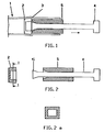
- Fig. 1 shows schematically in a cross-section a tubular member (1) as a single tube, e.g. thin-walled Al-tubing, provided with a closing baffle (2) firmly interlocked in an indentation (3) running circumferentially in the tube wall.
- An expansion mandrel (4) carrying a support die (5) can be seen under its withdrawal from the tube after accomplished expansion of the baffle (2) and plastic deformation of the tube wall resulting in formation of the indentation (3).
- Figs. 2-4 illustrating schematically the individual steps in the process of pre-forming, inserting and fastening of the baffle inside the tube
- the baffles is shown in Fig. 2 as a cup-shaped plug (2) with outwardly diverging walls (22) having a cross-section complementary-shaped to the inner cross-section of the actual tubular member.
- the cross-section can be circular, oval or as shown in Fig. 2a rectangular.
- Fig. 2a is a sectional view taken on line I-I of Fig. 2.
- An expansion mandrel (4) is provided with a head part (41) designed and dimensioned so that the plug (2) can receive this head part and by pressing into a suitable die (not shown in the picture) achieve a full encapsulation of the mandrel head by collapsed (crimped) plug wall (22) - see Fig. 3.
- a locating or support die (5) is attached to the mandrel (4) in order to insert the whole assembled system with the plug (2) into the tube void and positioned at the desired location within the tube. It is apparent from Fig. 4 that the suitable design of the support die allows it also to be used as a locating or positioning device for the plug by adapting its length and/or positioning with regard to the open (accessible) end of the tube. The support die is then firmly held in the place, and the expansion mandrel (4) is withdrawn from the plug causing the plug walls (22) to expand uniformly against the inner surface of the tube. The tube wall around the expanding plug (4) is subjected to a local plastic deformation resulting in formation of a circumferential indentation (3) as shown in Fig. 1.
- Fig. 4a is a sectional view of the tube taken on line I-I of Fig. 4 and shows an elliptical cross-section of the tube.
- FIG. 5 it is shown an embodiment of the closing system according to the present invention where optionally an outside support ring (6) is located on the tube over the plug (2) prior to the expansion step.
- an outside support ring (6) By proper dimensioning and choice of material in the ring, e.g. hardened aluminum, an additional increase of the fastening forces can be achieved.
- Fig. 5a is a sectional viw taken on line I-I of Fig. 5, showing in this case a circular (round) cross-section of the tube.
Landscapes
- Engineering & Computer Science (AREA)
- General Engineering & Computer Science (AREA)
- Mechanical Engineering (AREA)
- Physics & Mathematics (AREA)
- Thermal Sciences (AREA)
- Shaping Metal By Deep-Drawing, Or The Like (AREA)
- Attitude Control For Articles On Conveyors (AREA)
- Lift Valve (AREA)
- Pipe Accessories (AREA)
- Heat-Exchange Devices With Radiators And Conduit Assemblies (AREA)
- Separation Using Semi-Permeable Membranes (AREA)
- Adhesives Or Adhesive Processes (AREA)
- Forging (AREA)
- Earth Drilling (AREA)
- Quick-Acting Or Multi-Walled Pipe Joints (AREA)
- Tubes (AREA)
- Rigid Containers With Two Or More Constituent Elements (AREA)
- Forms Removed On Construction Sites Or Auxiliary Members Thereof (AREA)
- Body Structure For Vehicles (AREA)
Priority Applications (1)
| Application Number | Priority Date | Filing Date | Title |
|---|---|---|---|
| AT86112648T ATE50350T1 (de) | 1985-09-13 | 1986-09-12 | Verfahren zum befestigen von stopfen innerhalb eines rohres und so erhaltenes verschlusssystem. |
Applications Claiming Priority (2)
| Application Number | Priority Date | Filing Date | Title |
|---|---|---|---|
| US77602685A | 1985-09-13 | 1985-09-13 | |
| US776026 | 1985-09-13 |
Publications (3)
| Publication Number | Publication Date |
|---|---|
| EP0214670A2 true EP0214670A2 (de) | 1987-03-18 |
| EP0214670A3 EP0214670A3 (en) | 1987-06-24 |
| EP0214670B1 EP0214670B1 (de) | 1990-02-07 |
Family
ID=25106254
Family Applications (1)
| Application Number | Title | Priority Date | Filing Date |
|---|---|---|---|
| EP86112648A Expired - Lifetime EP0214670B1 (de) | 1985-09-13 | 1986-09-12 | Verfahren zum Befestigen von Stopfen innerhalb eines Rohres und so erhaltenes Verschlusssystem |
Country Status (6)
| Country | Link |
|---|---|
| EP (1) | EP0214670B1 (de) |
| JP (1) | JP2585545B2 (de) |
| KR (1) | KR950009921B1 (de) |
| AT (1) | ATE50350T1 (de) |
| BR (1) | BR8604383A (de) |
| DE (1) | DE3668979D1 (de) |
Cited By (3)
| Publication number | Priority date | Publication date | Assignee | Title |
|---|---|---|---|---|
| EP0669490A1 (de) * | 1994-02-25 | 1995-08-30 | ABB Reaktor GmbH | Verfahren zum Erzielen einer dichten Verbindung zwischen einem Rohr und einer Hülse |
| WO1998022745A1 (en) * | 1996-11-19 | 1998-05-28 | Avdel Textron Limited | Expandable sealing plug |
| WO2017005751A1 (fr) * | 2015-07-07 | 2017-01-12 | Valeo Systemes Thermiques | Dispositif de fermeture pour micro tube de faisceau de stockage d'une batterie thermique de stockage |
Family Cites Families (3)
| Publication number | Priority date | Publication date | Assignee | Title |
|---|---|---|---|---|
| AT326779B (de) * | 1968-07-01 | 1975-12-29 | Waagner Biro Ag | Fernbediente rohrverschliesseinrichtung |
| JPS5993241A (ja) * | 1973-10-09 | 1984-05-29 | レイチエム コーポレーシヨン | 管閉塞用器具 |
| JPS55128332A (en) * | 1979-03-24 | 1980-10-04 | Sumitomo Metal Ind Ltd | Method and device for closing pipe end |
-
1986
- 1986-09-10 KR KR1019860007567A patent/KR950009921B1/ko not_active Expired - Fee Related
- 1986-09-12 JP JP61214242A patent/JP2585545B2/ja not_active Expired - Fee Related
- 1986-09-12 BR BR8604383A patent/BR8604383A/pt not_active IP Right Cessation
- 1986-09-12 AT AT86112648T patent/ATE50350T1/de not_active IP Right Cessation
- 1986-09-12 EP EP86112648A patent/EP0214670B1/de not_active Expired - Lifetime
- 1986-09-12 DE DE8686112648T patent/DE3668979D1/de not_active Expired - Lifetime
Cited By (5)
| Publication number | Priority date | Publication date | Assignee | Title |
|---|---|---|---|---|
| EP0669490A1 (de) * | 1994-02-25 | 1995-08-30 | ABB Reaktor GmbH | Verfahren zum Erzielen einer dichten Verbindung zwischen einem Rohr und einer Hülse |
| US5787933A (en) * | 1994-02-25 | 1998-08-04 | Abb Reaktor Gmbh | Method of obtaining a leakproof connection between a tube and a sleeve |
| WO1998022745A1 (en) * | 1996-11-19 | 1998-05-28 | Avdel Textron Limited | Expandable sealing plug |
| WO2017005751A1 (fr) * | 2015-07-07 | 2017-01-12 | Valeo Systemes Thermiques | Dispositif de fermeture pour micro tube de faisceau de stockage d'une batterie thermique de stockage |
| FR3038707A1 (fr) * | 2015-07-07 | 2017-01-13 | Valeo Systemes Thermiques | Dispositif de fermeture pour micro tube de faisceau de stockage d'une batterie thermique de stockage |
Also Published As
| Publication number | Publication date |
|---|---|
| EP0214670A3 (en) | 1987-06-24 |
| DE3668979D1 (de) | 1990-03-15 |
| BR8604383A (pt) | 1987-05-12 |
| EP0214670B1 (de) | 1990-02-07 |
| JPS6264434A (ja) | 1987-03-23 |
| JP2585545B2 (ja) | 1997-02-26 |
| KR870003337A (ko) | 1987-04-16 |
| ATE50350T1 (de) | 1990-02-15 |
| KR950009921B1 (ko) | 1995-09-01 |
Similar Documents
| Publication | Publication Date | Title |
|---|---|---|
| US4762152A (en) | Assembly of a closing baffle inside a tubular member | |
| KR940002832B1 (ko) | 매니포울드 및 그의 제조방법 | |
| US5524938A (en) | Tube connection for a water box of a motor vehicle heat exchanger | |
| US5178211A (en) | Heat exchanger | |
| KR960005791B1 (ko) | 열 교환기용의 일체로된 매니폴드 제조 방법 및 그 방법에 의해 제조된 매니폴드 | |
| EP0745824B1 (de) | Wärmetauscher und Verfahren zu dessen Herstellung | |
| US5713611A (en) | Connection of a plate and tubular members | |
| US4467511A (en) | Method for the conformation of a metallic tube, particularly for a heat exchanger, and a heat exchanger provided with tubes thus conformed | |
| KR0144564B1 (ko) | 열교환기와 이 열교환기의 열교환요소의 배열에 단부판을 밀봉장착하기 위한 방법 | |
| RU2001105992A (ru) | Крепление фитинг/коллектор и способ его монтажа для теплообменника | |
| US6662447B2 (en) | Method and apparatus for the production of double-walled hollow sections by means of internal high-pressure forming | |
| US6186225B1 (en) | Heat exchanger with an integrated tank and head sheet | |
| US6179049B1 (en) | Heat exchanger with an integrated tank and head sheet | |
| US5101889A (en) | Heat exchanger u-bend dipped joint with vent for clearance space | |
| US4077559A (en) | Oval bell concept | |
| US6178636B1 (en) | Heat exchanger tube to header swaging process | |
| EP0214670A2 (de) | Verfahren zum Befestigen von Stopfen innerhalb eines Rohres und so erhaltenes Verschlusssystem | |
| US5421086A (en) | Method of punching a through opening in a tubular wall | |
| JPH1151592A (ja) | 熱交換器の製造方法 | |
| KR100311834B1 (ko) | 열교환기 | |
| CN1157032A (zh) | 用于汽车空调冷凝器集管的弯头连接装置 | |
| EP0574645B1 (de) | Verfahren zum Verbinden von Warmaustauscherelementen an einer Platte und Werkzeug zum Verformen des Rohrendes von einem länglichen Durchschnitt zu einem kreisförmigen Durchschnitt | |
| US6308410B1 (en) | Method for fixing transverse partitions in the tubular fluid box of a heat exchanger | |
| JPH11190597A (ja) | 熱交換器の伝熱管接続方法 | |
| CA1303605C (en) | Heat exchanger tube having embossed ring bell and brazing ring |
Legal Events
| Date | Code | Title | Description |
|---|---|---|---|
| PUAI | Public reference made under article 153(3) epc to a published international application that has entered the european phase |
Free format text: ORIGINAL CODE: 0009012 |
|
| AK | Designated contracting states |
Kind code of ref document: A2 Designated state(s): AT BE CH DE FR GB IT LI NL SE |
|
| PUAL | Search report despatched |
Free format text: ORIGINAL CODE: 0009013 |
|
| AK | Designated contracting states |
Kind code of ref document: A3 Designated state(s): AT BE CH DE FR GB IT LI NL SE |
|
| 17P | Request for examination filed |
Effective date: 19871124 |
|
| 17Q | First examination report despatched |
Effective date: 19880412 |
|
| GRAA | (expected) grant |
Free format text: ORIGINAL CODE: 0009210 |
|
| AK | Designated contracting states |
Kind code of ref document: B1 Designated state(s): AT BE CH DE FR GB IT LI NL SE |
|
| REF | Corresponds to: |
Ref document number: 50350 Country of ref document: AT Date of ref document: 19900215 Kind code of ref document: T |
|
| ET | Fr: translation filed | ||
| REF | Corresponds to: |
Ref document number: 3668979 Country of ref document: DE Date of ref document: 19900315 |
|
| ITF | It: translation for a ep patent filed | ||
| PLBE | No opposition filed within time limit |
Free format text: ORIGINAL CODE: 0009261 |
|
| STAA | Information on the status of an ep patent application or granted ep patent |
Free format text: STATUS: NO OPPOSITION FILED WITHIN TIME LIMIT |
|
| 26N | No opposition filed | ||
| ITTA | It: last paid annual fee | ||
| EAL | Se: european patent in force in sweden |
Ref document number: 86112648.0 |
|
| REG | Reference to a national code |
Ref country code: GB Ref legal event code: IF02 |
|
| PGFP | Annual fee paid to national office [announced via postgrant information from national office to epo] |
Ref country code: SE Payment date: 20020904 Year of fee payment: 17 |
|
| PGFP | Annual fee paid to national office [announced via postgrant information from national office to epo] |
Ref country code: FR Payment date: 20020910 Year of fee payment: 17 |
|
| PGFP | Annual fee paid to national office [announced via postgrant information from national office to epo] |
Ref country code: GB Payment date: 20020911 Year of fee payment: 17 Ref country code: AT Payment date: 20020911 Year of fee payment: 17 |
|
| PGFP | Annual fee paid to national office [announced via postgrant information from national office to epo] |
Ref country code: CH Payment date: 20020916 Year of fee payment: 17 |
|
| PGFP | Annual fee paid to national office [announced via postgrant information from national office to epo] |
Ref country code: DE Payment date: 20020918 Year of fee payment: 17 |
|
| PGFP | Annual fee paid to national office [announced via postgrant information from national office to epo] |
Ref country code: NL Payment date: 20020930 Year of fee payment: 17 |
|
| PGFP | Annual fee paid to national office [announced via postgrant information from national office to epo] |
Ref country code: BE Payment date: 20021129 Year of fee payment: 17 |
|
| PG25 | Lapsed in a contracting state [announced via postgrant information from national office to epo] |
Ref country code: GB Free format text: LAPSE BECAUSE OF NON-PAYMENT OF DUE FEES Effective date: 20030912 Ref country code: AT Free format text: LAPSE BECAUSE OF NON-PAYMENT OF DUE FEES Effective date: 20030912 |
|
| PG25 | Lapsed in a contracting state [announced via postgrant information from national office to epo] |
Ref country code: SE Free format text: LAPSE BECAUSE OF NON-PAYMENT OF DUE FEES Effective date: 20030913 |
|
| PG25 | Lapsed in a contracting state [announced via postgrant information from national office to epo] |
Ref country code: LI Free format text: LAPSE BECAUSE OF NON-PAYMENT OF DUE FEES Effective date: 20030930 Ref country code: CH Free format text: LAPSE BECAUSE OF NON-PAYMENT OF DUE FEES Effective date: 20030930 Ref country code: BE Free format text: LAPSE BECAUSE OF NON-PAYMENT OF DUE FEES Effective date: 20030930 |
|
| BERE | Be: lapsed |
Owner name: *NORSK HYDRO A/S Effective date: 20030930 |
|
| PG25 | Lapsed in a contracting state [announced via postgrant information from national office to epo] |
Ref country code: NL Free format text: LAPSE BECAUSE OF NON-PAYMENT OF DUE FEES Effective date: 20040401 Ref country code: DE Free format text: LAPSE BECAUSE OF NON-PAYMENT OF DUE FEES Effective date: 20040401 |
|
| EUG | Se: european patent has lapsed | ||
| GBPC | Gb: european patent ceased through non-payment of renewal fee |
Effective date: 20030912 |
|
| REG | Reference to a national code |
Ref country code: CH Ref legal event code: PL |
|
| PG25 | Lapsed in a contracting state [announced via postgrant information from national office to epo] |
Ref country code: FR Free format text: LAPSE BECAUSE OF NON-PAYMENT OF DUE FEES Effective date: 20040528 |
|
| NLV4 | Nl: lapsed or anulled due to non-payment of the annual fee |
Effective date: 20040401 |
|
| REG | Reference to a national code |
Ref country code: FR Ref legal event code: ST |
|
| PG25 | Lapsed in a contracting state [announced via postgrant information from national office to epo] |
Ref country code: IT Free format text: LAPSE BECAUSE OF NON-PAYMENT OF DUE FEES;WARNING: LAPSES OF ITALIAN PATENTS WITH EFFECTIVE DATE BEFORE 2007 MAY HAVE OCCURRED AT ANY TIME BEFORE 2007. THE CORRECT EFFECTIVE DATE MAY BE DIFFERENT FROM THE ONE RECORDED. Effective date: 20050912 |