EP0214863A2 - Leichtabtastvorrichtung - Google Patents
Leichtabtastvorrichtung Download PDFInfo
- Publication number
- EP0214863A2 EP0214863A2 EP86306915A EP86306915A EP0214863A2 EP 0214863 A2 EP0214863 A2 EP 0214863A2 EP 86306915 A EP86306915 A EP 86306915A EP 86306915 A EP86306915 A EP 86306915A EP 0214863 A2 EP0214863 A2 EP 0214863A2
- Authority
- EP
- European Patent Office
- Prior art keywords
- light beam
- scanning
- mirror
- angle
- scanning apparatus
- Prior art date
- Legal status (The legal status is an assumption and is not a legal conclusion. Google has not performed a legal analysis and makes no representation as to the accuracy of the status listed.)
- Withdrawn
Links
Images

Classifications
-
- G—PHYSICS
- G02—OPTICS
- G02B—OPTICAL ELEMENTS, SYSTEMS OR APPARATUS
- G02B26/00—Optical devices or arrangements for the control of light using movable or deformable optical elements
- G02B26/08—Optical devices or arrangements for the control of light using movable or deformable optical elements for controlling the direction of light
- G02B26/10—Scanning systems
-
- G—PHYSICS
- G02—OPTICS
- G02B—OPTICAL ELEMENTS, SYSTEMS OR APPARATUS
- G02B26/00—Optical devices or arrangements for the control of light using movable or deformable optical elements
- G02B26/08—Optical devices or arrangements for the control of light using movable or deformable optical elements for controlling the direction of light
- G02B26/0816—Optical devices or arrangements for the control of light using movable or deformable optical elements for controlling the direction of light by means of one or more reflecting elements
Definitions
- the present invention relates to a light beam scanning apparatus which employs a vibrating mirror to reflect a light beam onto a body surface, to rapidly scan across that surface.
- the invention relates to a method for reducing errors in scanning speed and position during operation of such a light beam scanning apparatus.
- a light beam scanning apparatus of this type generally employs a resonance scanner, which causes a mirror to vibrate about a central axis.
- a resonance scanner which causes a mirror to vibrate about a central axis.
- the operation of such a scanning apparatus will be discussed with reference to Fig. 1, in which a sinusoidally vibrating mirror 1 reflects a light beam 5 from a light beam source 2, after the beam has passed through a condensor lens 4.
- the reflected light beam falls on a surface of a body 3, at a position on that surface which will be referred to in the following as the scanning position.
- the amount of angular deflection of the reflected light beam due to rotation of the scanning mirror 1 is equal to twice the angle of rotation of the mirror.
- this angular deflection of the light beam will be referred to as the scanning angle and designated as ⁇ , so that the corresponding angle of rotation of the vibrating mirror will be equal to cp/2.
- This angle of rotation of the mirror obeys the relationship:
- Correction method (1) above has the disadvantage that an optical correction lens is expensive, while in addition it is necessary to position the lens to a high degree of accuracy. These factors will result in a high manufacturing cost. This method also has the disadvantage that the position of the lens may be shifted if the apparatus is subjected to vibration or shock, so that the reliability of the apparatus will be low. If correction method (2) above is used. then the data clock must utilize a high frequency, so that the component cost of the apparatus is high, and in addition it is necessary to perform temperature compensation of electronic circuit components. Moreover, the size of the required circuit board will be large, so that the overall size of the apparatus will be large.
- correction of scanning position error is achieved by utilizing only a part of the total angular movement of the mirror, for scanning across the body surface, and by selecting the maximum angle of rotation of the mirror such as to maximize the amount of mutual cancellation of factors which result in scanning position error, as described hereinafter.
- a light beam scanning apparatus comprises a source of a light beam, a condensor lens through which the light beam is passed, a mirror positioned to reflect the light beam emerging from the condensor lens onto a surface of a body, and resonance scanner means for vibrating the mirror sinusoidally with a fixed period of vibration for thereby scanning the light beam along a fixed scanning direction along successive positions on the body surface, in which, designating the amplitude of vibration of the mirror as ⁇ m(degrees) and assuming that a scanning phase angle of the light beam is zero when the light beam falls upon a predetermined median position on the body surface and that the scanning phase angle attains a value ⁇ w when the light beam falls upon an outermost position on the body surface, the following relationship is satisfied:
- Fig. 1 An embodiment of a light beam scanning apparatus according to the present invention will be described, referring first to Fig. 1.
- the light beam 5 is deflected by mirror 1 to fall on a surface of body 3 which is being scanned.
- Mirror 1 is periodically sinusoidally vibrated by a resonance scanner unit (not shown in drawings).
- a resonance scanner unit not shown in drawings.
- mirror 1 is positioned at the median point of its sinusoidal vibration, and this will be assumed as a reference point of origin for defining scanning time points and phase angles in the following description.
- the light beam source 2 in Fig. 1 can be for example a laser, while the scanned body 3 can be for example a photo-sensing element, a screen, etc.
- the scanning position displacement y i.e. the change in position of incidence of the scanning light beam on the surface of body 3 resulting from deflection by the scanning angle ⁇ p is given as:
- Fig. 2 shows the relationship between deviation of velocity of displacement of scanning position v and the scanning angle ⁇ for the apparatus of Fig. 1, taking the maximum value of scanning angle ⁇ m as a parameter.
- the relative deviation of this velocity v i.e. the deviation with respect to the value of velocity when ⁇ is zero, is plotted along the vertical axis, while the scanning angle is plotted along the horizontal axis.
- the relative deviation of the velocity of displacement of scanning position attains an extremely small value when the maximum light beam scanning angle ⁇ m is approximately 42°, i.e. as shown by curve 6 in Fig. 2.
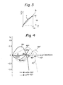
- numeral 8 denotes a linear relationship which is an ideally linear approximation to this relationship between light beam position and time, with time being plotted along the horizontal axis and light beam position (as y/f ) plotted along the vertical axis.
- the median point of vibration of the scanning mirror i.e. the time point at which the light beam deflected by the mirror falls upon a centrally situated position on a surface of body 3 will be taken as the time point of origin.
- the maximum angular range through which the light beam is scanned by the resonance scanner mirror is + ⁇ p m , and the angle through which the light beam is scanned across the body 3 is ⁇ w , i.e. the angle through which the light beam is scanned from the median position of the scanning mirror, as defined hereinabove, until the light beam falls upon an outermost position on the surface of body 3 being scanned, i.e. the position on the body surface which is at the limit of the scanning path over the surface.
- the time point at which the light beam attains this outermost position will be designated as t w , taking the time point at which the scanning beam is at the median position thereof (i.e. when mirror 1 is in the central position shown in Fig. 1) as the time origin.
- the relationship between the scanning angle ⁇ w and time point t w is given as follows:
- Fig. 4 is a graphical diagram to show deviations from linearity of the relationship between light beam scanning position and time, for different values of the maximum scanning angle ⁇ m (i.e. the maximum angle by which the scanning beam is deflected from the median position thereof, as illustrated in Fig. 1), and for two different values of the mirror vibration phase angle (i.e. the scanning light beam phase angle. expressed as ⁇ t. where ⁇ is the velocity of angular rotation of the vibrating mirror) at the time point when the scanning angle becomes (p w , this specific phase angle being designated as ⁇ w .
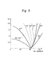
- Fig. 5 shows the relationship between values of ⁇ w and ⁇ m which minimize the relative deviation i.e. which minimize the positional error.
- the maximum values of relative deviation i.e. the values of relative deviation which occur when the light beam is scanning an outermost position on the surface being scanned
- ⁇ w are plotted along the vertical axis.
- a light beam scanning apparatus according to the present invention was applied to a laser beam printer. It was found that if A4 paper is used for printing, and if the value of the relative deviation described above is varied while sample characters are printed. then the print quality deteriorates significantly when the relative deviation exceeds 2%.
- Table 1 shows values of ⁇ w and corresponding values of ⁇ 1 , where ⁇ 1 denotes low values of ⁇ p m for which the relative deviation will remain within 2%, corresponding values of ⁇ 3 , where ⁇ 3 denotes high values of ⁇ m for which the relative deviation will remain within 2%, and ⁇ 2 , where ⁇ 2 denotes values of (p m such that the relative deviation attains a minimum.
- a light beam scanning apparatus enables position errors to be eliminated without the need for utilizing an optical correction lens or a non-periodic data clock circuit.
- the invention enables the production of a light beam scanning apparatus having low cost, high reliability, and small size.
Landscapes
- Physics & Mathematics (AREA)
- General Physics & Mathematics (AREA)
- Optics & Photonics (AREA)
- Mechanical Optical Scanning Systems (AREA)
- Facsimile Scanning Arrangements (AREA)
Applications Claiming Priority (2)
| Application Number | Priority Date | Filing Date | Title |
|---|---|---|---|
| JP60197180A JPS6256921A (ja) | 1985-09-06 | 1985-09-06 | 光走査装置 |
| JP197180/85 | 1985-09-06 |
Publications (2)
| Publication Number | Publication Date |
|---|---|
| EP0214863A2 true EP0214863A2 (de) | 1987-03-18 |
| EP0214863A3 EP0214863A3 (de) | 1989-06-21 |
Family
ID=16370133
Family Applications (1)
| Application Number | Title | Priority Date | Filing Date |
|---|---|---|---|
| EP86306915A Withdrawn EP0214863A3 (de) | 1985-09-06 | 1986-09-08 | Leichtabtastvorrichtung |
Country Status (2)
| Country | Link |
|---|---|
| EP (1) | EP0214863A3 (de) |
| JP (1) | JPS6256921A (de) |
Cited By (5)
| Publication number | Priority date | Publication date | Assignee | Title |
|---|---|---|---|---|
| EP0471291A3 (en) * | 1990-08-07 | 1992-04-22 | Omron Corporation | Optical scanner |
| EP0499236A3 (en) * | 1991-02-12 | 1993-06-16 | Omron Corporation | Improved optical scanner and bar code reader employing same |
| EP0336743B1 (de) * | 1988-04-05 | 1994-12-14 | Canon Kabushiki Kaisha | Optisches Abtastsystem |
| WO2003067509A1 (de) * | 2002-02-08 | 2003-08-14 | Jenoptik Ldt Gmbh | Anordnung und verfahren zur messung an einem resonanten schwinger und seiner steuerung und einstellung einer pixelbreite |
| US8037736B2 (en) * | 2008-01-14 | 2011-10-18 | International Business Machines Corporation | Non-linearity determination of positioning scanner of measurement tool |
Family Cites Families (8)
| Publication number | Priority date | Publication date | Assignee | Title |
|---|---|---|---|---|
| US3873180A (en) * | 1973-09-10 | 1975-03-25 | Ampex | Light beam scanning system with scan angle demagnification |
| US3962538A (en) * | 1974-11-21 | 1976-06-08 | Xerox Corporation | Flying spot scanning system with virtual scanners |
| US4002830A (en) * | 1975-01-22 | 1977-01-11 | Laser Graphic Systems Corporation | Apparatus for compensating for optical error in a rotative mirror |
| US4108532A (en) * | 1976-06-23 | 1978-08-22 | Canon Kabushiki Kaisha | Light beam scanning device |
| US4310757A (en) * | 1978-07-07 | 1982-01-12 | Pitney Bowes Inc. | Apparatus for correcting scanning speed in a polygon used for laser scanning |
| JPS5547006U (de) * | 1978-09-18 | 1980-03-27 | ||
| JPS5857108A (ja) * | 1981-09-30 | 1983-04-05 | Fujitsu Ltd | 光走査方式 |
| JPS589228A (ja) * | 1982-05-14 | 1983-01-19 | Canon Inc | 光束走査光学系 |
-
1985
- 1985-09-06 JP JP60197180A patent/JPS6256921A/ja active Pending
-
1986
- 1986-09-08 EP EP86306915A patent/EP0214863A3/de not_active Withdrawn
Cited By (9)
| Publication number | Priority date | Publication date | Assignee | Title |
|---|---|---|---|---|
| EP0336743B1 (de) * | 1988-04-05 | 1994-12-14 | Canon Kabushiki Kaisha | Optisches Abtastsystem |
| EP0471291A3 (en) * | 1990-08-07 | 1992-04-22 | Omron Corporation | Optical scanner |
| US5245463A (en) * | 1990-08-07 | 1993-09-14 | Omron Corporation | Optical scanner |
| US5444565A (en) * | 1990-08-07 | 1995-08-22 | Omron Corporation | Optical scanner |
| EP0499236A3 (en) * | 1991-02-12 | 1993-06-16 | Omron Corporation | Improved optical scanner and bar code reader employing same |
| US5828051A (en) * | 1991-02-12 | 1998-10-27 | Omron Corporation | Optical scanner and bar code reader employing same |
| WO2003067509A1 (de) * | 2002-02-08 | 2003-08-14 | Jenoptik Ldt Gmbh | Anordnung und verfahren zur messung an einem resonanten schwinger und seiner steuerung und einstellung einer pixelbreite |
| US8037736B2 (en) * | 2008-01-14 | 2011-10-18 | International Business Machines Corporation | Non-linearity determination of positioning scanner of measurement tool |
| US8990961B2 (en) | 2008-01-14 | 2015-03-24 | International Business Machines Corporation | Non-linearity determination of positioning scanner of measurement tool |
Also Published As
| Publication number | Publication date |
|---|---|
| EP0214863A3 (de) | 1989-06-21 |
| JPS6256921A (ja) | 1987-03-12 |
Similar Documents
| Publication | Publication Date | Title |
|---|---|---|
| US4577095A (en) | Automatic focusing apparatus for a semiconductor pattern inspection system | |
| US5185676A (en) | Beam scanning apparatus and apparatus for writing image information | |
| US5594556A (en) | Scanner having a misalignment detector | |
| US4919499A (en) | Optical printer of scaning type | |
| JPH01237513A (ja) | 光ビーム偏向走査装置 | |
| JPH11133333A (ja) | 流体フィルムベアリングおよびクロススキャンならびにインスキャン誤差の能動補正を有するポリゴンスキャナ | |
| US5287125A (en) | Raster output scanner with process direction spot position control | |
| US5592324A (en) | Cylindrical inner surface scanner and imaging control method in cylindrical inner surface scanner | |
| EP0214863A2 (de) | Leichtabtastvorrichtung | |
| US3923395A (en) | Process for measuring the distance of and the speed component of an object perpendicular to a reference line | |
| JPH11135913A (ja) | 走査システムにおける画像非直線性補正のための方法及び装置 | |
| EP0052524B1 (de) | Apparat zum genauen Verstellen eines Gegenstandes gemäss einer vorherbestimmten Bewegung | |
| US4264119A (en) | Scanning optical system | |
| EP0420198B1 (de) | Strahlabtastvorrichtung und Bildinformationsschreibvorrichtung | |
| US5307198A (en) | Scanner with combined predictive and diffractive feedback control of beam position | |
| JPH0933834A (ja) | 2ビームレーザー走査光学系 | |
| JP2713625B2 (ja) | 画像形成装置 | |
| JPS6120849B2 (de) | ||
| JPH0264521A (ja) | 走査ビーム軌跡補正方法 | |
| KR960009042Y1 (ko) | 레이저빔 주사광학계의 빔 위치 조절장치 | |
| Beiser | Monogon laser scanner with no line wobble | |
| EP0336743A2 (de) | Optisches Abtastsystem | |
| JPH0635291A (ja) | 多重画像形成装置 | |
| JPH09179053A (ja) | 光走査装置 | |
| JPH01205119A (ja) | 光走査装置 |
Legal Events
| Date | Code | Title | Description |
|---|---|---|---|
| PUAI | Public reference made under article 153(3) epc to a published international application that has entered the european phase |
Free format text: ORIGINAL CODE: 0009012 |
|
| AK | Designated contracting states |
Kind code of ref document: A2 Designated state(s): DE FR GB IT |
|
| 17P | Request for examination filed |
Effective date: 19870601 |
|
| PUAL | Search report despatched |
Free format text: ORIGINAL CODE: 0009013 |
|
| AK | Designated contracting states |
Kind code of ref document: A3 Designated state(s): DE FR GB IT |
|
| 18D | Application deemed to be withdrawn |
Effective date: 19881001 |
|
| RIN1 | Information on inventor provided before grant (corrected) |
Inventor name: SUZUKI, NAOMICHIC/O TECH. LAB. OF CITIZEN WATCH C Inventor name: MASUBUCHI, SADAOC/O TECH. LAB. OF CITIZEN WATCH C |